iec 61131-5 programmable controllers - communications
Bạn đang xem bản rút gọn của tài liệu. Xem và tải ngay bản đầy đủ của tài liệu tại đây (418.43 KB, 106 trang )
INTERNATIONAL
STANDARD
IEC
61131-5
First edition
2000-11
Programmable controllers –
Part 5:
Communications
Automates programmables –
Partie 5:
Communications
Reference number
IEC 61131-5:2000(E)
Copyright International Electrotechnical Commission
Provided by IHS under license with IEC
Licensee=Technip Abu Dabhi/5931917101
Not for Resale, 02/12/2006 07:02:40 MST
No reproduction or networking permitted without license from IHS
``,`,`,,,``````,,``,,``,,,,`,-`-`,,`,,`,`,,`
Publication numbering
As from 1 January 1997 all IEC publications are issued with a designation in the
60000 series. For example, IEC 34-1 is now referred to as IEC 60034-1.
Consolidated editions
The IEC is now publishing consolidated versions of its publications. For example,
edition numbers 1.0, 1.1 and 1.2 refer, respectively, to the base publication, the
base publication incorporating amendment 1 and the base publication incorporating
amendments 1 and 2.
Further information on IEC publications
The technical content of IEC publications is kept under constant review by the IEC,
thus ensuring that the content reflects current technology. Information relating to
this publication, including its validity, is available in the IEC Catalogue of
publications (see below) in addition to new editions, amendments and corrigenda.
Information on the subjects under consideration and work in progress undertaken
by the technical committee which has prepared this publication, as well as the list
of publications issued, is also available from the following:
•
IEC Web Site (www.iec.ch)
•
Catalogue of IEC publications
The on-line catalogue on the IEC web site (www.iec.ch/catlg-e.htm) enables
you to search by a variety of criteria including text searches, technical
committees and date of publication. On-line information is also available on
recently issued publications, withdrawn and replaced publications, as well as
corrigenda.
•
IEC Just Published
This summary of recently issued publications (www.iec.ch/JP.htm) is also
available by email. Please contact the Customer Service Centre (see below) for
further information.
•
Customer Service Centre
If you have any questions regarding this publication or need further assistance,
please contact the Customer Service Centre:
Email:
Tel: +41 22 919 02 11
Fax: +41 22 919 03 00
Copyright International Electrotechnical Commission
Provided by IHS under license with IEC
Licensee=Technip Abu Dabhi/5931917101
Not for Resale, 02/12/2006 07:02:40 MST
No reproduction or networking permitted without license from IHS
``,`,`,,,``````,,``,,``,,,,`,-`-`,,`,,`,`,,`
INTERNATIONAL
STANDARD
IEC
61131-5
First edition
2000-11
Programmable controllers –
Part 5:
Communications
Automates programmables –
Partie 5:
Communications
PRICE CODE
IEC 2000
Copyright - all rights reserved
No part of this publication may be reproduced or utilized in any form or by any means, electronic or
mechanical, including photocopying and microfilm, without permission in writing from the publisher.
International Electrotechnical Commission 3, rue de Varembé Geneva, Switzerland
Telefax: +41 22 919 0300 e-mail: IEC web site
X
For price, see current catalogue
Commission Electrotechnique Internationale
International Electrotechnical Commission
Copyright International Electrotechnical Commission
Provided by IHS under license with IEC
Licensee=Technip Abu Dabhi/5931917101
Not for Resale, 02/12/2006 07:02:40 MST
No reproduction or networking permitted without license from IHS
``,`,`,,,``````,,``,,``,,,,`,-`-`,,`,,`,`,,`
– 2 – 61131-5
IEC:2000(E)
CONTENTS
Page
FOREWORD 6
Clause
1 Scope 8
2 Normative references 8
3 Definitions 9
4 Symbols and abbreviations 11
5 Models 11
5.1 PC network communication model 11
5.2 PC functional model 12
5.3 PC hardware model 14
5.4 Software model 14
6 PC communication services 15
6.1 PC subsystems and their status 15
6.2 Application specific functions 22
7 PC communication function blocks 28
7.1 Overview of the communication function blocks 28
7.2 Semantic of communication FB parameters 29
7.3 Device verification 34
7.4 Polled data acquisition 38
7.5 Programmed data acquisition 41
7.6 Parametric control 51
7.7 Interlocked control 54
7.8 Programmed alarm report 61
7.9 Connection management 69
7.10 Example for the use of communication function blocks 73
8 Compliance and implementer specific features and parameters 76
8.1 Compliance 76
8.2 Implementation specific features and parameters 77
Annex A (normative) Mapping to ISO/IEC 9506-5 78
Annex B (normative) PC behavior using ISO/IEC 9506-2 98
Figure 1 – Scope of this part of IEC 61131 8
Figure 2 – PC communication model 12
Figure 3 – Programmable controller functional model 13
Figure 4 – Programmable controller hardware model 14
Figure 5 – PC software model 15
Figure 6 – Programmable controller power supply 19
Figure 7 – Type description of status information 21
Figure 8 – Interlocked control timeline 24
Figure 9 – Function REMOTE_VAR 31
Copyright International Electrotechnical Commission
Provided by IHS under license with IEC
Licensee=Technip Abu Dabhi/5931917101
Not for Resale, 02/12/2006 07:02:40 MST
No reproduction or networking permitted without license from IHS
``,`,`,,,``````,,``,,``,,,,`,-`-`,,`,,`,`,,`
61131-5
IEC:2000(E) – 3 –
Figure 10 – Principle of status signalling 32
Figure 11 – Timing diagram of the ERROR and STATUS outputs 32
Figure 12 – STATUS function block 34
Figure 13 – USTATUS function block 35
Figure 14 – Timing diagram of the STATUS function block 35
Figure 15 – State diagram of STATUS function block 36
Figure 16 – State diagram of USTATUS function block 37
Figure 17 – READ function block 39
Figure 18 – Timing diagram of READ function block 39
Figure 19 – State diagram of READ function block 40
Figure 20 – Programmed data acquisition data flow 41
Figure 21 – USEND function block 42
Figure 22 – URCV function block 42
Figure 23 – Timing diagram of USEND and URCV function blocks 43
Figure 24 – State diagram of USEND function block 43
Figure 25 – State diagram of URCV function block 45
Figure 26 – BSEND function block 47
Figure 27 – BRCV function block 48
Figure 28 – Timing diagram of BSEND and BRCV function blocks 48
Figure 29 – State diagram of BSEND function block 49
Figure 30 – State diagram of BRCV function block 50
Figure 31 – WRITE function block 52
Figure 32 – Timing diagram of WRITE function block 53
Figure 33 – State diagram of WRITE function block 53
Figure 34 – SEND function block 55
Figure 35 – RCV function block 56
Figure 36 – Timing diagram of SEND and RCV function blocks 57
Figure 37 – State diagram of SEND function block 58
Figure 38 – State diagram of RCV function block 60
Figure 39 – NOTIFY function block 62
Figure 40 – ALARM function block 63
Figure 41 – Timing diagram of ALARM function block 64
Figure 42 – State diagram of NOTIFY function block 65
Figure 43 – State diagram of ALARM function block 67
Figure 44 – CONNECT function block 69
Figure 45 – Timing diagram of CONNECT function block 70
Figure 46 – State diagram of CONNECT function block 71
Figure 47 – Example in function block diagram language 76
Table 1 – Status presenting entities 16
Table 2 – PC summary status 17
Table 3 – Status of I/O subsystem 18
Table 4 – Status of processing unit 18
Copyright International Electrotechnical Commission
Provided by IHS under license with IEC
Licensee=Technip Abu Dabhi/5931917101
Not for Resale, 02/12/2006 07:02:40 MST
No reproduction or networking permitted without license from IHS
``,`,`,,,``````,,``,,``,,,,`,-`-`,,`,,`,`,,`
– 4 – 61131-5
IEC:2000(E)
Table 5 – Status of power supply 19
Table 6 – Status of memory 19
Table 7 – Status of communication subsystem 20
Table 8 – Status of implementer specific subsystem 20
Table 9 – Presentation of status information 21
Table 10 – Device verification features 23
Table 11 – Data acquisition features 23
Table 12 – Control features 24
Table 13 – Alarm reporting features 25
Table 14 – Startable and stoppable units 25
Table 15 – Meaning of I/O State 26
Table 16 – I/O state 26
Table 17 – Execution and I/O control features 26
Table 18 – Loadable units 27
Table 19 – Application program transfer features 27
Table 20 – Connection management features 28
Table 21 – Overview of the communication function blocks 28
Table 22 – Semantic of communication FB parameters 30
Table 23 – Values of the SCOPE parameter 31
Table 24 – Value and interpretation of the STATUS output 33
Table 25 – Transitions of the STATUS state diagram 36
Table 26 – Action table for STATUS state diagram 36
Table 27 – Transitions of USTATUS state diagrams 37
Table 28 – Action table of USTATUS state diagram 37
Table 29 – Transitions of the READ state diagram 40
Table 30 – Action table for READ state diagram 41
Table 31 – Transitions of the USEND state diagram 44
Table 32 – Action table for USEND state diagram 44
Table 33 – Transitions of URCV state diagrams 45
Table 34 – Action table of URCV state diagram 46
Table 35 – Transitions of the BSEND state diagram 49
Table 36 – Action table for BSEND state diagram 50
Table 37 – Transitions of BRCV state diagrams 51
Table 38 – Action table of BRCV state diagram 51
Table 39 – Transitions of the WRITE state diagram 54
Table 40 – Action table for WRITE state diagram 54
Table 41 – Transitions of the SEND state diagram 58
Table 42 – Action table for SEND state diagram 59
Table 43 – Transitions of RCV state diagrams 60
Table 44 – Action table of RCV state diagram 61
Table 45 – Transitions of the NOTIFY state diagram 65
Table 46 – Action table for NOTIFY state diagram 66
Table 47 – Transitions of the ALARM state diagram 68
Copyright International Electrotechnical Commission
Provided by IHS under license with IEC
Licensee=Technip Abu Dabhi/5931917101
Not for Resale, 02/12/2006 07:02:40 MST
No reproduction or networking permitted without license from IHS
``,`,`,,,``````,,``,,``,,,,`,-`-`,,`,,`,`,,`
61131-5
IEC:2000(E) – 5 –
Table 48 – Action table for ALARM state diagram 68
Table 49 – Transitions of the CONNECT state diagram 72
Table 50 – Action table for CONNECT state diagram 73
Table 51 – Table titles and relevant tables for compliance 76
Table 52 – Implementation specific features and parameters 77
Table A.1 – Type description mapping 81
Table A.2 – Mapping of the SCOPE and SC_ID parameter 81
Table A.3 – Size prefix of direct representation 82
Table A.4 – Transition mapping of the STATUS state diagram 84
Table A.5 – Action mapping for STATUS state diagram 84
Table A.6 – Transition mapping of USTATUS state diagram 84
Table A.7 – Action mapping of USTATUS state diagram 84
Table A.8 – Transition mapping of the READ state diagram 85
Table A.9 – Action mapping for READ state diagram 85
Table A.10 – Transition mapping of the USEND state diagram 86
Table A.11 – Action mapping for USEND state diagram 86
Table A.12 – Transition mapping of URCV state diagram 86
Table A.13 – Action mapping for URCV state diagram 87
Table A.14 – Transition mapping of the BSEND state diagram 87
Table A.15 – Action mapping for BSEND state diagram 88
Table A.16 – Transition mapping of BRCV state diagram 88
Table A.17 – Action mapping for BRCV state diagram 89
Table A.18 – Transition mapping of the WRITE state diagram 90
Table A.19 – Action mapping for WRITE state diagram 90
Table A.20 – Transition mapping of the SEND state diagram 90
Table A.21 – Action mapping for SEND state diagram 91
Table A.22 – Transition mapping of RCV state diagram 91
Table A.23 – Action mapping of RCV state diagram 92
Table A.24 – Transition mapping of the NOTIFY state diagram 94
Table A.25 – Action mapping for NOTIFY state diagram 94
Table A.26 – Transition mapping of the ALARM state diagram 95
Table A.27 – Action mapping for ALARM state diagram 95
Table A.28 – Transitions of the CONNECT state diagram 96
Table A.29 – Action mapping for CONNECT state diagram 96
Table A.30 – Implementation specific features and parameters 97
Table B.1 – CreateProgramInvocation service defaults 98
Table B.2 – Program Invocation service defaults for I/O State parameter 98
Table B.3 – Implementation specific features and parameters 99
Copyright International Electrotechnical Commission
Provided by IHS under license with IEC
Licensee=Technip Abu Dabhi/5931917101
Not for Resale, 02/12/2006 07:02:40 MST
No reproduction or networking permitted without license from IHS
``,`,`,,,``````,,``,,``,,,,`,-`-`,,`,,`,`,,`
– 6 – 61131-5
IEC:2000(E)
INTERNATIONAL ELECTROTECHNICAL COMMISSION
____________
PROGRAMMABLE CONTROLLERS –
Part 5: Communications
FOREWORD
1) The IEC (International Electrotechnical Commission) is a worldwide organization for standardization comprising
all national electrotechnical committees (IEC National Committees). The object of the IEC is to promote
international co-operation on all questions concerning standardization in the electrical and electronic fields. To
this end and in addition to other activities, the IEC publishes International Standards. Their preparation is
entrusted to technical committees; any IEC National Committee interested in the subject dealt with may
participate in this preparatory work. International, governmental and non-governmental organizations liaising
with the IEC also participate in this preparation. The IEC collaborates closely with the International Organization
for Standardization (ISO) in accordance with conditions determined by agreement between the two
organizations.
2) The formal decisions or agreements of the IEC on technical matters express, as nearly as possible, an
international consensus of opinion on the relevant subjects since each technical committee has representation
from all interested National Committees.
3) The documents produced have the form of recommendations for international use and are published in the form
of standards, technical specifications, technical reports or guides and they are accepted by the National
Committees in that sense.
4) In order to promote international unification, IEC National Committees undertake to apply IEC International
Standards transparently to the maximum extent possible in their national and regional standards. Any
divergence between the IEC Standard and the corresponding national or regional standard shall be clearly
indicated in the latter.
5) The IEC provides no marking procedure to indicate its approval and cannot be rendered responsible for any
equipment declared to be in conformity with one of its standards.
6) Attention is drawn to the possibility that some of the elements of this International Standard may be the subject
of patent rights. The IEC shall not be held responsible for identifying any or all such patent rights.
International Standard IEC 61131-5 has been prepared by subcommittee 65B: Devices, of IEC
technical committee 65: Industrial-process measurement and control.
The text of this standard is based on the following documents:
FDIS Report on voting
65B/411/FDIS 65B/420/RVD
Full information on the voting for the approval of this standard can be found in the report on
voting indicated in the above table.
This publication has been drafted in accordance with the ISO/IEC Directives, Part 3.
This part should be read in conjunction with the other parts of IEC 61131. IEC 61131 consists
of the following parts under the general title:
Programmable controllers
.
Part 1:1992, General information.
Part 2:1992, Equipment requirements and tests.
Part 3:1993, Programming languages.
Part 4:1994, User guidelines (published as technical report IEC TR 61131-4)
Part 5:2000, Communications
Part 8:2000, Guidelines for the application and implementation of programming languages
(published as technical report IEC TR 61131-8)
Copyright International Electrotechnical Commission
Provided by IHS under license with IEC
Licensee=Technip Abu Dabhi/5931917101
Not for Resale, 02/12/2006 07:02:40 MST
No reproduction or networking permitted without license from IHS
``,`,`,,,``````,,``,,``,,,,`,-`-`,,`,,`,`,,`
61131-5
IEC:2000(E) – 7 –
Annexes A and B form an integral part of this standard.
Annex C is for information only.
Where a conflict exists between this and other IEC standards (except basic safety standards),
the provisions of this standard should be considered to govern in the area of programmable
controllers and their associated peripherals.
The committee has decided that the contents of this publication will remain unchanged until
2006. At this date, the publication will be
•
reconfirmed;
•
withdrawn;
•
replaced by a revised edition, or
•
amended.
A bilingual version of this standard may be issued at a later date.
Copyright International Electrotechnical Commission
Provided by IHS under license with IEC
Licensee=Technip Abu Dabhi/5931917101
Not for Resale, 02/12/2006 07:02:40 MST
No reproduction or networking permitted without license from IHS
``,`,`,,,``````,,``,,``,,,,`,-`-`,,`,,`,`,,`
– 8 – 61131-5
IEC:2000(E)
PROGRAMMABLE CONTROLLERS –
Part 5: Communications
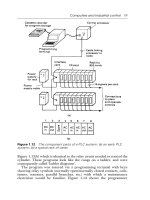
1 Scope
This part of IEC 61131 specifies communication aspects of a programmable controller. It
specifies from the viewpoint of a PC how any device can communicate with a PC as a server
and how a PC can communicate with any device. In particular, it specifies the behavior of the
PC as it provides services on behalf of other devices and the services the PC application
program can request from other devices. It is not intended to specify how any device can
communicate with any device using a PC as a router or gateway. The behavior of the PC as a
communication client and server is specified independent of the particular communication
subsystem, but the communication functionality may be dependent on the capabilities of the
communication subsystem used.
Any device
PC
Any device
Scope of IEC 61131-5
IEC 2247/2000
Figure 1 – Scope of this part of IEC 61131
The scope of this part is a subset of the "communication model" shown in figure 2 of
IEC 61131-3; namely figures 2c and 2d are included in the scope of this part. Additionally, the
means defined in this part of IEC 61131 may be used for communications within a program or
between programs.
The mapping of the PC behavior to some particular communications subsystems is provided in
the annexes.
2 Normative references
The following normative documents contain provisions which, through reference in this text,
constitute provisions of this part of IEC 61131. For dated references, subsequent amendments
to, or revisions of, any of these publications do not apply. However, parties to agreements
based on this part of IEC 61131 are encouraged to investigate the possibility of applying the
most recent editions of the normative documents indicated below. For undated references, the
latest edition of the normative document referred to applies. Members of ISO and IEC maintain
registers of currently valid International Standards.
IEC 60050-351:1998,
International Electrotechnical Vocabulary – Part 351: Automatic control
IEC 61131-1:1992,
Programmable controllers – Part 1: General Information
IEC 61131-2:1992,
Programmable controllers – Part 2: Equipment requirements and tests
IEC 61131-3:1993,
Programmable controllers – Part 3: Programming languages
ISO/IEC 2382-1:1993,
Information technology – Vocabulary – Part 1: Fundamental terms
ISO/IEC 9506-1:1990,
Industrial automation systems
–
Manufacturing Message Specification –
Part 1: Service definition
Copyright International Electrotechnical Commission
Provided by IHS under license with IEC
Licensee=Technip Abu Dabhi/5931917101
Not for Resale, 02/12/2006 07:02:40 MST
No reproduction or networking permitted without license from IHS
``,`,`,,,``````,,``,,``,,,,`,-`-`,,`,,`,`,,`
61131-5
IEC:2000(E) – 9 –
ISO/IEC 9506-2:1990,
Industrial automation systems – Manufacturing Message Specification –
Part 2: Protocol specification
3 Definitions
For the purpose of this part of IEC 61131, the following definitions apply.
This part of IEC 61131 is based on the concepts of parts 1 to 3 of IEC 61131 and makes use of
the following terms defined in other international standards.
Definitions from other publications
IEC 60050-351
control
monitoring
IEC 61131-1
application program (2.1)
application program archiving (4.6.4)
cold restart (2.56)
input (2.25)
main processing unit (2.32)
modifying the application program (4.6.2.6)
output (2.40)
programmable controller (2.50)
programmable controller system (2.51)
testing the application program (4.6.2.5)
warm restart (2.56)
IEC 61131-3
access path (1.3.2)
direct representation (1.3.23)
invocation (1.3.43)
program (verb, 1.3.60)
sub-element (2.3.3.1)
ISO/IEC 2382-1
data
ISO/IEC 9506-1
client
download
event (clause 15)
server
uninterruptible variable access (12.1.1.1)
upload
variable
Copyright International Electrotechnical Commission
Provided by IHS under license with IEC
Licensee=Technip Abu Dabhi/5931917101
Not for Resale, 02/12/2006 07:02:40 MST
No reproduction or networking permitted without license from IHS
``,`,`,,,``````,,``,,``,,,,`,-`-`,,`,,`,`,,`
– 10 – 61131-5
IEC:2000(E)
Definitions of this part
3.1
alarm
event which signals a specific condition
3.2
data acquisition
collection of data for the purpose of process monitoring and report generation
3.3
direct operator interface
when the client can communicate to the operator interface via the communication system with
no application program interaction
3.4
device verification
allows other devices to determine if the PC is able to perform its intended function in the
control system
3.5
health
the health of a PC or its subsystems is specified by returning one, and only one, of the three
possible values. They are, in order of decreasing health: GOOD, WARNING and BAD
3.6
interlocked control
control through the synchronization of data exchanges between two parties. At various points in
time, one party is waiting for the other party to deliver some expected data
3.7
local
internal to the PC; opposite of remote
3.8
parametric control
control by the client writing to control variables residing in the PC
3.9
processing unit
part of the main processing unit. It is the portion of a PC system which is responsible for the
storage of the application program and data and the execution of the application program.
A PC system has one or more processing units
3.10
program verification
testing of a PC application program to verify that it performs the function(s) it was designed to
do in the process environment
3.11
recipe
description of procedures, or data for those procedures, or both, for making a product which
uses the process or machinery that the controller is attached to, which is different from a
previous product
Copyright International Electrotechnical Commission
Provided by IHS under license with IEC
Licensee=Technip Abu Dabhi/5931917101
Not for Resale, 02/12/2006 07:02:40 MST
No reproduction or networking permitted without license from IHS
``,`,`,,,``````,,``,,``,,,,`,-`-`,,`,,`,`,,`
61131-5
IEC:2000(E) – 11 –
3.12
remote
external to the PC; opposite of local
3.13
state
the state of the PC system is indicated by a list of attributes, each of which may be TRUE or
FALSE. Zero, one, or more of these attributes may be TRUE at the same time
3.14
unsolicited
performed without an explicit request
4 Symbols and abbreviations
These are some abbreviations frequently used in this part of IEC 61131. These terms are
defined or referenced in clause 3 of this part of IEC 61131.
CFB Communication function block
FB Function block
I/O Input and output
IEC International Electrotechnical Commission
ISO International Organization for Standardization
MMS Manufacturing Message Specification, ISO/IEC 9506-1 and ISO/IEC 9506-2
OSI Open Systems Interconnection
PADT Programming and debugging tool
PC Programmable controller
PU Processing unit
5 Models
This clause specifies the models which are used in the remainder of this part of IEC 61131.
5.1 PC network communication model
A programmable controller supplies some specific application functions to the rest of the
control system. It may also request functions from other programmable controllers. The
communication functions defined in this part of IEC 61131 are based on a communication
subsystem that can report communication errors to the signal processing function of the PC
(see 5.2).
The following diagram illustrates the devices in a communication network, showing three
possible devices that request PC functions (clients) from PC 2. The two highlighted PCs are in
the scope of this part of IEC 61131.
Copyright International Electrotechnical Commission
Provided by IHS under license with IEC
Licensee=Technip Abu Dabhi/5931917101
Not for Resale, 02/12/2006 07:02:40 MST
No reproduction or networking permitted without license from IHS
``,`,`,,,``````,,``,,``,,,,`,-`-`,,`,,`,`,,`
– 12 – 61131-5
IEC:2000(E)
Communication system
Supervisory
controller
Other-end system
which talks to PC
Programmable
controller 1
Programmable
controller 2
Client
Client Client Server
Machinery or
process
IEC 2248/2000
NOTE From the communication viewpoint the 'supervisory controller' and the 'other-end system which talks to PC'
mentioned in this figure exhibit the same behavior to a PC communication server, i.e., they submit requests to the
PC2.
Figure 2 – PC communication model
A PC may use its client function to communicate with any device if it behaves like a PC.
5.2 PC functional model
A PC consists of several functions (see figure 3). For a PC within the scope of this part of
IEC 61131, at least one communication function is present.
The following diagram is taken from IEC 61131-1, figure 1. It is designed to illustrate some of
the subsystems of a typical PC.
Copyright International Electrotechnical Commission
Provided by IHS under license with IEC
Licensee=Technip Abu Dabhi/5931917101
Not for Resale, 02/12/2006 07:02:40 MST
No reproduction or networking permitted without license from IHS
``,`,`,,,``````,,``,,``,,,,`,-`-`,,`,,`,`,,`
61131-5
IEC:2000(E) – 13 –
Other systems
Mains
supply
Communication
functions
Power
supply
function
Signal
processing
function
MAN-MACHINE
INTERFACE
functions
debugging, and
testing functions
Programming,
OPERATING
SYSTEM
functions
PROGRAM
storage functions
APPLICATION
functions
DATA
storage
PROGRAM
execution
APPLICATION
INTERFACE functions to
sensors and actuators
Machine / Process
Operator
APPLICATION
programmer
IEC 2249/2000
Figure 3 – Programmable controller functional model
There is a function that is part of the PC system, but usually external to the PC itself, known as
the programming and debugging tool (PADT). The PADT is modelled as interacting with the PC
via the communications function.
The Interface Function to Sensors and Actuators can have I/O which are local or remote to the
Main Processing Unit (see 5.3 for the hardware model). The Interface Function to Sensors and
Actuators has two attributes for each Application Program which defines how the PC is
monitoring and controlling the machine/process. The input attribute has the following states:
•
inputs provided to the Application Program are being supplied by the sensors,
•
inputs provided to the Application Program are being held in the current state.
The output attribute has the following states:
•
the actuators are being controlled by the Application Program,
•
the actuators are being held in the current state.
Copyright International Electrotechnical Commission
Provided by IHS under license with IEC
Licensee=Technip Abu Dabhi/5931917101
Not for Resale, 02/12/2006 07:02:40 MST
No reproduction or networking permitted without license from IHS
``,`,`,,,``````,,``,,``,,,,`,-`-`,,`,,`,`,,`
– 14 – 61131-5
IEC:2000(E)
5.3 PC hardware model
The following figure shows the PC hardware model. It shows the modules that make up a PC.
A PC subsystem consists of one or more modules. The following figure corresponds to figure
B.1 of IEC 61131-1 and figure 1 of IEC 61131-2.
Memory(ies)
and
processing unit(s)
Input module(s)
Output module(s)
Communication module(s)
Power supply unit(s)
Main processing unit
Remote I/O station(s)
Peripherals
Implementer-specific subsystem(s)
IEC 2250/200
0
Figure 4 – Programmable controller hardware model
5.4 Software model
Figure 5 shows the PC software model defined in IEC 61131-3, figure 1. It illustrates the basic
high-level language elements of the PC programming languages and their interrelationships.
These consist of elements which are programmed using the languages defined in IEC 61131-3,
i.e. programs and function blocks; and configuration elements, namely, configurations,
resources, tasks, global variables, and access paths, which support the installation of
programmable controller programs into programmable controller systems.
A configuration is the language element which corresponds to a programmable controller
system as defined in IEC 61131-1. A resource corresponds to a "signal processing function"
and its "man-machine interface" and "sensor and actuator interface" functions (if any) as
defined in IEC 61131-1. A configuration contains one or more resources, each of which
contains one or more programs executed under the control of zero or more tasks. A program
may contain zero or more function blocks or other language elements as defined in
IEC 61131-3.
Configurations and resources can be started and stopped via the "operator interface",
"programming, testing, and monitoring", or "operating system" functions defined in
IEC 61131-1. The mechanisms for the starting and stopping of configurations and resources
via communication services are defined in this part of IEC 61131.
Programs, resources, global variables, access paths (and their corresponding access
privileges), and configurations can be loaded or deleted by the "communication function"
defined in IEC 61131-1. The loading or deletion of a configuration or resource shall be
equivalent to the loading or deletion of all the elements it contains.
Access
paths and their corresponding access privileges allow to access variables of a PC via
communication services.
Copyright International Electrotechnical Commission
Provided by IHS under license with IEC
Licensee=Technip Abu Dabhi/5931917101
Not for Resale, 02/12/2006 07:02:40 MST
No reproduction or networking permitted without license from IHS
``,`,`,,,``````,,``,,``,,,,`,-`-`,,`,,`,`,,`
61131-5
IEC:2000(E) – 15 –
Confi
g
uration
Resource
Task Task
Pro
g
ram Pro
g
ram
FB FB
Resource
Task Task
Pro
g
ram Pro
g
ram
FB FB
Global and directly
Access paths
Execution control path
Variable access paths
FB
Function block
Variable
or
represented variables
Communication function
NOTE 1 This figure is illustrative only. The graphical representation is not normative.
NOTE 2 In a configuration with a single resource, the resource need not be explicitly represented.
Figure 5 – PC software model
6 PC communication services
This clause describes the concept of status information of a PC and provides a specification of
the services the PC provides to the control system via the communication subsystem. (The
next clause specifies how the PC application program can use the communication subsystem
to interact with other devices.)
6.1 PC subsystems and their status
A PC can provide status, which includes state information and fault indications.
Status can be reported on some of the subsystems identified in the following figure. In addition,
there is a summary status that provides general information about the PC.
IEC 2251/2000
Copyright International Electrotechnical Commission
Provided by IHS under license with IEC
Licensee=Technip Abu Dabhi/5931917101
Not for Resale, 02/12/2006 07:02:40 MST
No reproduction or networking permitted without license from IHS
``,`,`,,,``````,,``,,``,,,,`,-`-`,,`,,`,`,,`
– 16 – 61131-5
IEC:2000(E)
Table 1 – Status presenting entities
No. Status presenting entities
1 PC (as a whole)
2 I/O subsystem (includes Input and Output modules and other intelligent I/O devices)
3 Processing unit
4 Power supply subsystem
5 Memory subsystem
6 Communication subsystem
7 Implementer specific subsystems
NOTE The status is intended to provide information about the controller including its
hardware and firmware subsystems, not considering configuration information. It is not
intended to provide information about the controlled process nor the PC application program.
The status data contains information concerning the state and the health of the PC and its
subsystems.
There are two concepts used in this part of IEC 61131 related to status: health and state. The
"health" of a PC or its subsystems is specified by returning one and only one of the three
possible values. The semantics associated with each value is specified below. They are, in
order of decreasing health:
a) GOOD – If TRUE, the PC (or the specified subsystem) has not detected any problems
which would prohibit it from performing the intended function;
b) WARNING – If TRUE, the PC (or the specified subsystem) has not detected any problems
which would prohibit it from performing the intended function, but it has detected at least
one problem which could place some limits on its abilities. The limit may be time,
performance, etc. (see the following statements for further definition of these limits);
c) BAD – If TRUE, the PC (or the specified subsystem) has detected at least one problem
which could prohibit it from performing the intended function.
The "state" of the PC system is indicated by a list of attributes, each of which may be TRUE or
FALSE. Zero, one, or more of these attributes may be TRUE at the same time. The semantics
associated with each attribute is specified in the remainder of this clause.
Each of the status information can also have implementer specified attributes. Some examples
of implementer specified attributes are:
a) additional error diagnostics (e.g. EEPROM write cycles exceeded);
b) additional operational states (e.g. auto-calibrate enabled);
c) local key status (e.g. auto-restart required).
Implementations are not required to provide subsystem status. All instances of similar types of
subsystems present in a system are reported separately. The name of the subsystem can be
provided to allow differentiating subsystems of the same type.
6.1.1 PC summary status
The PC provides the following summary status information.
Copyright International Electrotechnical Commission
Provided by IHS under license with IEC
Licensee=Technip Abu Dabhi/5931917101
Not for Resale, 02/12/2006 07:02:40 MST
No reproduction or networking permitted without license from IHS
``,`,`,,,``````,,``,,``,,,,`,-`-`,,`,,`,`,,`
61131-5
IEC:2000(E) – 17 –
Table 2 – PC summary status
No. Item Description
1 Health GOOD All subsystems in the PC indicate a GOOD health condition
2 WARNING At least one subsystem indicates a WARNING health condition and no sub-
system indicates a BAD health condition
3 BAD At least one subsystem indicates a BAD health condition
4 Running If TRUE, this attribute indicates if at least one part of the user application has been loaded
and is under control of the PC
5 Local control If TRUE, this attribute indicates if local override control is active. If active, the ability to
control a PC and its subsystems from the network may be limited. For example, this could
be closely tied to the use of a local key switch
6 No outputs
disabled
If TRUE, this attribute indicates that the PC can change the physical state of all outputs as
a result of application program execution or other means. If not TRUE, the physical state of
some of the outputs are not affected (logical state may be affected). This is typically used
in the testing and modifying of application programs in the PC
7 No inputs
disabled
If TRUE, this attribute indicates that the PC can access the physical state of all inputs as a
result of application program execution or other means. If not TRUE, the physical state of
some inputs cannot be accessed. This is typically used in the testing and modifying of
application programs where the inputs can be simulated
8 Forced If TRUE, this attribute indicates that at least one I/O point associated with the PC has been
forced. When an Input is forced, the application program will receive the value specified by
the PADT instead of the actual value from the machine or process. When an output is
forced, the machine or process will receive the value specified by the PADT instead of the
value generated by execution of the application program. When a variable is forced, the
application program will use the value specified by the PADT instead of that generated by
the normal program execution
9 User application
present
If TRUE, this attribute indicates that the Processing Unit has at least one user application
present
10 I/O subsystem If TRUE, this attribute indicates "WARNING" or "BAD" which is caused by an I/O subsystem
11 Processing unit
subsystem
If TRUE, this attribute indicates "WARNING" or "BAD" which is caused by a processing unit
subsystem
12 Power supply
subsystem
If TRUE, this attribute indicates "WARNING" or "BAD" which is caused by a power supply
subsystem
13 Memory
subsystem
If TRUE, this attribute indicates "WARNING" or "BAD" which is caused by a memory
subsystem
14 Communication
subsystem
If TRUE, this attribute indicates "WARNING" or "BAD" which is caused by a communication
subsystem
15 Implementer
specified
subsystem
If TRUE, this attribute indicates "WARNING" or "BAD" which is caused by an implementer
specified subsystem
6.1.2 I/O subsystem
The PC provides the following status information of its I/O subsystem.
Copyright International Electrotechnical Commission
Provided by IHS under license with IEC
Licensee=Technip Abu Dabhi/5931917101
Not for Resale, 02/12/2006 07:02:40 MST
No reproduction or networking permitted without license from IHS
``,`,`,,,``````,,``,,``,,,,`,-`-`,,`,,`,`,,`
– 18 – 61131-5
IEC:2000(E)
Table 3 – Status of I/O subsystem
No. Item Description
1 Health GOOD indicates that there have been no errors detected in this I/O subsystem
2 WARNING indicates that a minor fault has been detected in the I/O subsystem. An
example of a minor fault is the occurrence of recoverable errors in the
communication with a remote I/O station
3 BAD indicates that a major fault has been detected in the I/O subsystem. An
example of a major fault is losing communication with a remote I/O station
4 No outputs
disabled
If TRUE, this attribute indicates that the PC can change the physical state of all outputs
associated with the specified I/O subsystem as a result of application program execution
or other means. If not TRUE, the physical state of some of the outputs is not affected
(logical state may be affected). This is typically used in the testing and modifying of
application programs in the PC
5 No inputs
disabled
If TRUE, this attribute indicates that the PC can access the physical state of all inputs
associated with the specified I/O subsystem as a result of application program execution
or other means. If not TRUE, the physical state some inputs cannot be accessed. This is
typically used in the testing and modifying of application programs where the inputs can
be simulated
6 I/O forced If TRUE, this attribute indicates that at least one I/O point associated with this subsystem
has been forced. When an Input is forced, the application program will receive the value
specified by the PADT instead of the actual value from the machine or process. When an
output is forced, the machine or process will receive the value specified by the PADT
instead of the value generated by execution of the application program
NOTE The definition of "major fault" and "minor fault" shall be provided by the implementer.
6.1.3 Processing unit
The PC provides the following status information of its processing unit.
Table 4 – Status of processing unit
No. Item Description
1
2
3
Health This attribute identifies the health of the processing unit. The implementer shall specify
the conditions when GOOD, WARNING or BAD are valid
4 Running If TRUE, this attribute indicates if at least one part of the user application has been
loaded and is under control of the processing unit
5 Local control If TRUE, this attribute indicates if local override control is active. If active, the ability to
control the processing unit from the network may be limited. For example, this could be
closely tied to the use of a local key switch
6 No outputs
disabled
If TRUE, this attribute indicates that the processing unit can change the physical state of
all outputs controlled by this processing unit as a result of application program execution
or other means. If not TRUE, the physical state of some of the outputs are not affected
(logical state may be affected). This is typically used in the testing and modifying of
application programs in the PU
7 No inputs
disabled
If TRUE, this attribute indicates that the processing unit can access the physical state of
all inputs accessible from this processing unit as a result of application program execution
or other means. If not TRUE, the physical state of some inputs cannot be accessed. This
is typically used in the testing and modifying of application programs where the inputs can
be simulated
8User
application
present
If TRUE, this attribute indicates that the Processing Unit has at least one User Application
present
9 Forced If TRUE, this attribute indicates that at least one variable associated with this Processing
Unit has been forced. When a variable is forced, the application program will use the
value specified by the PADT instead of that generated by the normal program execution.
Copyright International Electrotechnical Commission
Provided by IHS under license with IEC
Licensee=Technip Abu Dabhi/5931917101
Not for Resale, 02/12/2006 07:02:40 MST
No reproduction or networking permitted without license from IHS
``,`,`,,,``````,,``,,``,,,,`,-`-`,,`,,`,`,,`
61131-5
IEC:2000(E) – 19 –
6.1.4 Power supply subsystem
The PC can provide status information about any of the power supply subsystems; see figure 6
for the assumed configuration of a PC power supply. The requirements on power supplies of
PC systems and their behavior is described in IEC 61131-1 and IEC 61131-2.
Power supply
power supply
Redundant
Battery
Mains
Power to PC circuits
IEC 2252/2000
Figure 6 – Programmable controller power supply
Table 5 – Status of power supply
No. Item Description
1 Health GOOD indicates that there have been no problems detected in the power supply to
prevent it from remaining operable for an indefinite time
2 WARNING indicates that a problem has been detected in the power supply which may
cause to become inoperable in a limited time
3 BAD indicates that the power supply is not operable
4 In use If TRUE, this attribute indicates that the power supply subsystem is in use, i.e. it supplies
power to the PC
5 Mains
operating
If TRUE, this attribute indicates that the mains are supplying power within the range
specified for the power supply
6 Mains low If TRUE, this attribute indicates that the mains are not supplying power within the range
specified for the power supply
7 Battery
operating
If TRUE, this attribute indicates that the battery is supplying power within the range
specified for the power supply
8 Battery low If TRUE, this attribute indicates that the battery is not able to supply power within the
range specified for the power supply
9Protection
tripped
If TRUE, this attribute indicates that a protection device within the power supply has
removed a portion of the power to the PC
6.1.5 Memory subsystem
The PC provides the following status information of its memory subsystem.
Table 6 – Status of memory
No. Item Description
1 Health GOOD No errors have been found in the memory associated with this subsystem
2 WARNING At least one correctable error has been detected and no uncorrectable
errors have been detected
3 BAD At least one uncorrectable error has been detected
4Protected
1)
If TRUE, this attribute indicates that the memory in this memory subsystem has been
protected in that it cannot be modified. This generally indicates that the application
program located in this memory subsystem cannot be altered.
1)
This attribute models a logical state not physical characteristics of the subsystem. If
some portions of the memory are protected and some are not, these shall be reported as
multiple subsystems.
Copyright International Electrotechnical Commission
Provided by IHS under license with IEC
Licensee=Technip Abu Dabhi/5931917101
Not for Resale, 02/12/2006 07:02:40 MST
No reproduction or networking permitted without license from IHS
``,`,`,,,``````,,``,,``,,,,`,-`-`,,`,,`,`,,`
– 20 – 61131-5
IEC:2000(E)
6.1.6 Communication subsystem
The PC provides the following status information of its communication subsystem.
Table 7 – Status of communication subsystem
No. Item Description
1 Health GOOD indicates that either no errors or an acceptable number of recoverable
errors has occurred
2 WARNING indicates that more than an acceptable number of recoverable errors has
occurred
3 BAD indicates that the communication subsystem is not able to communicate
with all devices as intended
4 In use If TRUE, this attribute indicates that the communication subsystem is currently
operating. For example in the case of an MMS communication interface this means that
at least one application association is established. Otherwise, the implementer shall
define the semantic of this attribute
5 Local error If TRUE, this attribute indicates that there are some errors, internal to the communi-
cation subsystem, that inhibit operation
6 Remote error If TRUE, this attribute indicates that there are some errors, at devices being communi-
cated with, that inhibit operation
NOTE 1 The communication subsystem reporting its state may not be able to report its own bad state in the
way defined in this clause. But, within a PC system, several independent communication subsystems may
operate, and all of them may provide status information.
NOTE 2 It is intended that the implementer specific information will provide additional information about each
particular interface. ISO network interfaces also provide additional information via network management
functions.
6.1.7 Implementer specific subsystems
Other subsystems of a PC system shall be modelled as implementer specific subsystems.
Some examples of these subsystems are:
a) PID controller;
b) motion controller;
c) other auxiliary processors.
Table 8 – Status of implementer specific subsystem
No. Item Description
1 Health GOOD indicates that there have been no errors detected in this subsystem
2 WARNING indicates that a minor fault has been detected in this subsystem
3 BAD indicates that a major fault has been detected in this subsystem
NOTE The definition of "major fault" and "minor fault" shall be provided by the implementer.
6.1.8 Presentation of status information
The status information shall be presented using variables with a pre-defined access path in the
configuration declaration of the PC application program or shall be presented as a variable with
direct representation to a remote communication partner.
Copyright International Electrotechnical Commission
Provided by IHS under license with IEC
Licensee=Technip Abu Dabhi/5931917101
Not for Resale, 02/12/2006 07:02:40 MST
No reproduction or networking permitted without license from IHS
``,`,`,,,``````,,``,,``,,,,`,-`-`,,`,,`,`,,`
61131-5
IEC:2000(E) – 21 –
Table 9 – Presentation of status information
No. Presentation of status information
1 PC summary status as variable with pre-defined access path P_PCSTATE
2 PC summary status as variable with direct representation %S
3 PC summary status and status of all subsystems as variable with pre-defined access path P_PCSTATUS
4 Status information of each subsystem as a set of variables with direct representation %SC<n>
5 Type of each subsystem as a set of variables with direct representation %SU<n>
6 Name of each subsystem as a set of variables with direct representation %SN<n>
7 State of each subsystem as a set of variables with direct representation %SS<n>
8 Implementer specific status of each subsystem as a set of variables with direct representation %SI<n>
If the PC summary status shall be presented in a variable, it shall have the access path
P_PCSTATE which shall be pre-defined in the configuration declaration. The variable shall be
of type WORD and shall contain the PC summary status beginning with item number 1 at the
least significant bit upwards.
If the PC summary status shall be presented as a variable with direct representation, the direct
representation shall be %S and shall be of type WORD. It shall contain the PC summary status
beginning with item number 1 at the least significant bit upwards.
If the complete status information shall be presented as a variable, it shall have the access
path P_PCSTATUS pre-defined in the configuration section. This variable shall have a
structured type as follows:
ARRAY [0 p_NOS] OF
STRUCT
SUBSYSTEM : (SUMMARY, IO, PU, POWER, MEMORY, COMMUNICATION,
IMPLEMENTER);
NAME : STRING[<Max_Name_Len>];
STATE : ARRAY[0 15] OF BOOL;
SPECIFIC : ARRAY[0 p_BIT] OF BOOL;
END_STRUCT;
Figure 7 – Type description of status information
The array element with the number 0 shall contain the PC summary status, each element with
a higher number shall contain the status of one subsystem. The sub-element SUBSYSTEM
shall contain the type of the PC or of a subsystem. The sub-element NAME shall contain the
name of the PC or of a subsystem. The implementer shall specify the supported maximum
length for name strings, i.e. the value of Max_Name_Len. The sub-element STATE shall
contain the state information of the PC or of a subsystem as an array of BOOL in the same
order as specified in tables 2 to 8. The implementer shall specify the number of elements of the
array P_PCSTATUS i.e. the value of p_NOS, the supported types of subsystems, the semantic
of the values in the sub-element STATE for the implementer specific subsystem, the size of the
sub-element SPECIFIC, i.e. the value of p_BIT, and the semantic of the sub-element
SPECIFIC.
The status information of each subsystem may be presented as a variable with direct
representation %SC<n>, where <n> stands for a number between 0 (representing the PC
summary status) and the number of subsystems p_NOS. The variable shall have the same
internal representation as a variable with the type of the structure part of the type described in
the figure above.
IEC 2253/2000
Copyright International Electrotechnical Commission
Provided by IHS under license with IEC
Licensee=Technip Abu Dabhi/5931917101
Not for Resale, 02/12/2006 07:02:40 MST
No reproduction or networking permitted without license from IHS
``,`,`,,,``````,,``,,``,,,,`,-`-`,,`,,`,`,,`
– 22 – 61131-5
IEC:2000(E)
Additionally there may be a set of variables with direct representation %SU<n>, %SN<n>,
%SS<n>, and %SI<n>. The <n> stands for a number between 0 (representing the PC summary
status) and the number of subsystems p_NOS. The variables shall have the same internal
representation as a variable with the type of one of the structure sub-elements of the type
described in the figure above. In detail, the %SU<n> shall correspond to the sub-element
SUBSYSTEM, %SN<n> to the sub-element NAME, %SS<n> to the sub-element STATE, and
%SI<n> to the sub-element SPECIFIC.
6.2 Application specific functions
The remainder of this clause describes the functions which a PC provides to a control system,
using the communication subsystem, as illustrated in figure 2.
PC communication function PC as
requester
PC as
responder
Function block
available
Device verification yes yes yes
Data acquisition yes yes yes
Control yes yes yes
Synchronization between user applications yes yes yes
Alarm reporting yes no yes
Program execution and I/O control no yes no
Application program transfer no yes no
Connection management yes yes yes
Each of these is treated separately in the remainder of this clause. Not all functions are
available in all PCs. See clause 7 for the function block definitions.
There are some applications which combine the application categories defined below, for
example, supervisory control and data acquisition.
The following elements, while usually provided by PCs, are outside the scope of this part of
IEC 61131:
a) operator interface;
b) programming, testing, and modifying the application program, and program verification.
PCs have the ability to use operator interface devices. These devices are used by an operator
to monitor or modify the controlled process or both. They may also be used by a client system
to communicate with the operator.
Direct operator interface is when the client can communicate to the operator interface via the
communication system with no application program interaction.
Programming is the process of creating a PC application program on an instruction by
instruction or a function block by function block basis. Testing and modifying is the process of
finding and removing errors ("bugs") in an existing application program by making changes to
it. Program verification is the testing of a PC application program to verify that it performs the
function(s) it was designed to do in the process environment.
Copyright International Electrotechnical Commission
Provided by IHS under license with IEC
Licensee=Technip Abu Dabhi/5931917101
Not for Resale, 02/12/2006 07:02:40 MST
No reproduction or networking permitted without license from IHS
``,`,`,,,``````,,``,,``,,,,`,-`-`,,`,,`,`,,`
61131-5
IEC:2000(E) – 23 –
6.2.1 Device verification
This function is provided to allow other devices to determine if the PC is able to perform its
intended function in the automated system. A PC can provide status of itself and its
subsystems. Status includes health and state information. A device may explicitly request
status from the PC or the PC may initiate an unsolicited status report using services provided
by the communication interface. See 6.1 for the definition of health and state information of a
PC system and of its subsystems.
Table 10 – Device verification features
No. Device verification
1 Provide status information
2 Initiate unsolicited status reports
6.2.2 Data acquisition
Data contained in a PC is presented as variables. This data may come from a variety of
sources and may have a wide range of meanings. It can be obtained by the client through one
of several methods.
a) Polled – The client reads the value of one or more variables at a time or condition
determined by the client. The access to the variables may be controlled by the PC. Only
selected variables are accessible over the network.
b) Programmed – The data is provided by the PC to the client at a time or condition
determined by the PC application program.
c) Configured – The communications interface to the PC can be configured by a client to
initiate a data transfer to the client.
The kinds of variables in the PC which are visible to the communication system are:
a) variables with direct representation;
b) other variables which have access paths (see IEC 61131-3 for the definition of access paths).
If the directly represented variables are accessible for communication these variables shall use
the direct representation as an identifier. The PC server (i.e. the PC which owns the variables)
can interpret the identifier using an implementer defined algorithm.
NOTE Variables with direct representation can be used like "normal" variables while programming an application
program. An additional symbolic name may be assigned to a directly represented variable using the AT construct in
the variable declaration (see IEC 61131-3).
Typically there are thousands of these variables with direct representation even in a smaller PC. It is not
reasonable to hold the name and the address of all these variables in an object dictionary of a PC.
The PC system may restrict access to variables with direct representation. The conditions
(size, location, etc.) under which each data type supported by the PC can be uninterruptedly
accessed shall be specified by the implementer.
Table 11 – Data acquisition features
No. Data acquisition
1 Variables with direct representation are accessible
2 Access paths on configuration level
3 Access paths on program level
4 Means to restrict access to variables with direct representation
5 Conditions for uninterruptible access to variables
Copyright International Electrotechnical Commission
Provided by IHS under license with IEC
Licensee=Technip Abu Dabhi/5931917101
Not for Resale, 02/12/2006 07:02:40 MST
No reproduction or networking permitted without license from IHS
``,`,`,,,``````,,``,,``,,,,`,-`-`,,`,,`,`,,`