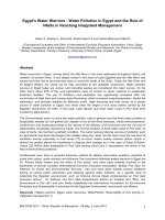
benson's microbiological applications laboratory manual in general microbiology - alfred e brown
Bạn đang xem bản rút gọn của tài liệu. Xem và tải ngay bản đầy đủ của tài liệu tại đây (32.24 MB, 455 trang )
Benson: Microbiological
Applications Lab Manual,
Eighth Edition
Front Matter Preface
© The McGraw−Hill
Companies, 2001
This eighth edition of Microbiological Applications
differs from the previous edition in that it has acquired
four new exercises and dropped three experiments. It
retains essentially the same format throughout, how-
ever. In response to requests for more emphasis on lab-
oratory safety, three new features have been incorpo-
rated into the text. In addition, several experiments
have been altered to improve simplicity and reliability.
The three exercises that were dropped pertain to fla-
gellar staining, bacterial conjugation, and nitrification in
soil. All of these exercises were either difficult to per-
form, unreliable, or of minimal pedagogical value.
To provide greater safety awareness in the labora-
tory, the following three features were added: (1) an
introductory laboratory protocol, (2) many cautionary
boxes dispersed throughout the text, and (3) a new ex-
ercise pertaining to aseptic technique.
The three-page laboratory protocol, which fol-
lows this preface, replaces the former introduction. It
provides terminology, safety measures, an introduc-
tion to aseptic technique, and other rules that apply to
laboratory safety.
To alert students to potential hazards in performing
certain experiments, caution boxes have been incorpo-
rated wherever they are needed. Although most of these
cautionary statements existed in previous editions, they
were not emphasized as much as they are in this edition.
Exercise 8 (Aseptic Technique) has been struc-
tured to provide further emphasis on culture tube han-
dling. In previous editions it was assumed that students
would learn these important skills as experiments were
performed. With the risk of being redundant, six pages
have been devoted to the proper handling of culture
tubes when making inoculation transfers.
Although most experiments remain unchanged,
there are a few that have been considerably altered.
Exercise 27 (Isolation of Anaerobic Phototrophic
Bacteria), in particular, is completely new. By using
the Winogradsky column for isolating and identifying
the phototrophic sulfur bacteria, it has been possible
to greatly enrich the scope of this experiment. Another
exercise that has been altered somewhat is Exercise
48, which pertains to oxidation and fermentation tests
that are used for identifying unknown bacteria.
The section that has undergone the greatest reor-
ganization is Part 10 (Microbiology of Soil). In the
previous edition it consisted of five exercises. In this
edition it has been expanded to seven exercises. A
more complete presentation of the nitrogen cycle is of-
fered in Exercise 58, and two new exercises (Exercises
61 and 62) are included that pertain to the isolation of
denitrifiers.
In addition to the above changes there has been
considerable upgrading of graphics throughout the
book. Approximately thirty-five illustrations have been
replaced. Several critical color photographs pertaining
to molds and physiological tests were also replaced to
bring about more faithful color representation.
I am greatly indebted to my editors, Jean Fornango
and Jim Smith, who made the necessary contacts for
critical reviews. As a result of their efforts the following
individuals have provided me with excellent sugges-
tions for improvement of this manual: Barbara Collins
at California Lutheran University, Thousand Oaks, CA;
Alfred Brown of Auburn University, Auburn, AL;
Lester A. Scharlin at El Camino College, Torrance, CA;
and Hershell Hanks at Collin County Community
College, Plano, TX.
vii
Preface
Benson: Microbiological
Applications Lab Manual,
Eighth Edition
Front Matter Laboratory Protocol
© The McGraw−Hill
Companies, 2001
Welcome to the exciting field of microbiology! The
intent of this laboratory manual is to provide you with
basic skills and tools that will enable you to explore a
vast microbial world. Its scope is incredibly broad in
that it includes a multitude of viruses, bacteria, proto-
zoans, yeasts, and molds. Both beneficial and harmful
ones will be studied. Although an in-depth study of
any single one of these groups could constitute a full
course by itself, we will be able to barely get ac-
quainted with them.
To embark on this study it will be necessary for
you to learn how to handle cultures in such a way that
they are not contaminated or inadvertently dispersed
throughout the classroom. This involves learning
aseptic techniques and practicing preventive safety
measures. The procedures outlined here address these
two aspects. It is of paramount importance that you
know all the regulations that are laid down here as
Laboratory Protocol.
Scheduling During the first week of this course
your instructor will provide you with a schedule of
laboratory exercises arranged in the order of their per-
formance. Before attending laboratory each day,
check the schedule to see what experiment or experi-
ments will be performed and prepare yourself so that
you understand what will be done.
Each laboratory session will begin with a short
discussion to brief you on the availability of materials
and procedures. Since the preliminary instructions
start promptly at the beginning of the period, it is ex-
tremely important that you are not late to class.
Personal Items When you first enter the lab, place
all personal items such as jackets, bags, and books in
some out of the way place for storage. Don’t stack
them on your desktop. Desk space is minimal and
must be reserved for essential equipment and your
laboratory manual. The storage place may be a
drawer, locker, coatrack, or perimeter counter. Your
instructor will indicate where they should be placed.
Attire A lab coat or apron must be worn at all times
in the laboratory. It will protect your clothing from ac-
cidental contamination and stains in the lab. When
leaving the laboratory, remove the coat or apron. In
addition, long hair must be secured in a ponytail to
prevent injury from Bunsen burners and contamina-
tion of culture material.
T
ERMINOLOGY
Various terms such as sterilization, disinfection, ger-
micides, sepsis, and aseptic techniques will be used
here. To be sure that you understand exactly what they
mean, the following definitions are provided.
Sterilization is a process in which all living mi-
croorganisms, including viruses, are destroyed. The
organisms may be killed with steam, dry heat, or in-
cineration. If we say an article is sterile, we understand
that it is completely free of all living microorganisms.
Generally speaking, when we refer to sterilization as it
pertains here to laboratory safety, we think, primarily,
in terms of steam sterilization with the autoclave. The
ultimate method of sterilization is to burn up the in-
fectious agents or incinerate them. All biological
wastes must ultimately be incinerated for disposal.
Disinfection is a process in which vegetative,
nonsporing microorganisms are destroyed. Agents
that cause disinfection are called disinfectants or
germicides. Such agents are used only on inanimate
objects because they are toxic to human and animal
tissues.
Sepsis is defined as the growth (multiplication) of
microorganisms in tissues of the body. The term asep-
sis refers to any procedure that prevents the entrance
of infectious agents into sterile tissues, thus prevent-
ing infection. Aseptic techniques refer to those prac-
tices that are used by microbiologists to exclude all
organisms from contaminating media or contacting
living tissues. Antiseptics are chemical agents (often
dilute disinfectants) that can be safely applied exter-
nally to human tissues to destroy or inhibit vegetative
bacteria.
A
SEPTIC
T
ECHNIQUES
When you start handling bacterial cultures as in
Exercises 9 and 10, you will learn the specifics of
aseptic techniques. Some of the basic things you will
do are as follows:
ix
Laboratory Protocol
Benson: Microbiological
Applications Lab Manual,
Eighth Edition
Front Matter Laboratory Protocol
© The McGraw−Hill
Companies, 2001
Hand Washing Before you start working in the lab,
wash your hands with a liquid detergent and dry them
with paper toweling. At the end of the period, before
leaving the laboratory, wash them again.
Tabletop Disinfection. The first chore of the day
will be to sponge down your desktop with a disinfec-
tant. This process removes any dust that may be pre-
sent and minimizes the chances of bacterial contami-
nation of cultures that you are about to handle.
Your instructor will indicate where the bottles of
disinfectant and sponges are located. At the end of the
period before leaving the laboratory, perform the same
procedure to protect students that may occupy your desk
in the next class.
Bunsen Burner Usage When using a Bunsen burner
to flame loops, needles, and test tubes, follow the pro-
cedures outlined in Exercise 8. Inoculating loops and
needles should be heated until they are red-hot. Before
they are introduced into cultures, they must be allowed
to cool down sufficiently to prevent killing organisms
that are to be transferred.
If your burner has a pilot on it and you plan to use
the burner only intermittently, use it. If your burner
lacks a pilot, turn off the burner when it is not being
used. Excessive unnecessary use of Bunsen burners in
a small laboratory can actually raise the temperature
of the room. More important is the fact that unat-
tended burner flames are a constant hazard to hair,
clothing, and skin.
The proper handling of test tubes, while transfer-
ring bacteria from one tube to another, requires a cer-
tain amount of skill. Test-tube caps must never be
placed down on the desktop while you are making in-
oculations. Techniques that enable you to make trans-
fers properly must be mastered. Exercise 8 pertains to
these skills.
Pipetting Transferring solutions or cultures by
pipette must always be performed with a mechanical
suction device. Under no circumstances is pipetting
by mouth allowed in this laboratory.
Disposal of Cultures and Broken Glass The fol-
lowing rules apply to culture and broken glass disposal:
1. Petri dishes must be placed in a plastic bag to be
autoclaved.
2. Unneeded test-tube cultures must be placed in a
wire basket to be autoclaved.
3. Used pipettes must be placed in a plastic bag for
autoclaving.
4. Broken glass should be swept up into a dustpan
and placed in a container reserved for broken
glass. Don’t try to pick up the glass fragments
with your fingers.
5. Contaminated material must never be placed in a
wastebasket.
A
CCIDENTAL
S
PILLS
All accidental spills, whether chemical or biological,
must be reported immediately to your instructor.
Although the majority of microorganisms used in
this laboratory are nonpathogens, some pathogens
will be encountered. It is for this reason that we must
treat all accidental biological spills as if pathogens
were involved.
Chemical spills are just as important to report be-
cause some agents used in this laboratory may be car-
cinogenic; others are poisonous; and some can cause
dermal damage such as blistering and depigmentation.
Decontamination Procedure Once your instructor
is notified of an accidental spill, the following steps
will take place:
1. Any clothing that is contaminated should be
placed in an autoclavable plastic bag and auto-
claved.
2. Paper towels, soaked in a suitable germicide, such
as 5% bleach, are placed over the spill.
3. Additional germicide should be poured around
the edges of the spill to prevent further
aerosolization.
4. After approximately 20 minutes, the paper tow-
els should be scraped up off the floor with an
autoclavable squeegee into an autoclavable
dust pan.
5. The contents of the dust pan are transferred to an
autoclavable plastic bag, which may itself be
placed in a stainless steel bucket or pan for trans-
port to an autoclave.
6. All materials, including the squeegee and dust-
pan, are autoclaved.
A
DDITIONAL
I
MPORTANT
R
EGULATIONS
Here are a few additional laboratory rules:
1. Don’t remove cultures, reagents, or other materi-
als from the laboratory unless you have been
granted specific permission.
2. Don’t smoke or eat food in the laboratory.
3. Make it a habit to keep your hands away from your
mouth. Obviously, labels are never moistened
with the tongue; use tap water or self-adhesive la-
bels instead.
Laboratory Protocol
x
Benson: Microbiological
Applications Lab Manual,
Eighth Edition
Front Matter Laboratory Protocol
© The McGraw−Hill
Companies, 2001
4. Always clean up after yourself. Gram-stained
slides that have no further use to you should be
washed and dried and returned to a slide box.
Coverslips should be cleaned, dried, and returned.
Staining trays should be rinsed out and returned to
their storage place.
5. Return all bulk reagent bottles to places of storage.
6. Return inoculating loops and needles to your stor-
age container. Be sure that they are not upside
down.
7. If you have borrowed something from someone,
return it.
8. Do not leave any items on your desk at the end of
the period.
9. Do not disturb another class at any time. Wait un-
til the class is dismissed.
10. Treat all instruments, especially microscopes,
with extreme care. If you don’t understand how a
piece of equipment functions, ask your instructor.
11. Work cooperatively with other students in group-
assigned experiments, but do your own analyses
of experimental results.
Laboratory Protocol
xi
Benson: Microbiological
Applications Lab Manual,
Eighth Edition
I. Microscopy Introduction
© The McGraw−Hill
Companies, 2001
1
Although there are many kinds of microscopes available to the mi-
crobiologist today, only four types will be described here for our
use: the brightfield, darkfield, phase-contrast, and fluorescence
microscopes. If you have had extensive exposure to microscopy in
previous courses, this unit may not be of great value to you; how-
ever, if the study of microorganisms is a new field of study for you,
there is a great deal of information that you need to acquire about
the proper use of these instruments.
Microscopes in a college laboratory represent a considerable
investment and require special care to prevent damage to the
lenses and mechanicals. The fact that a laboratory microscope
may be used by several different individuals during the day and
moved around from one place to another results in a much greater
chance for damage and wear to occur than if the instrument were
used by only one individual.
The complexity of some of the more expensive microscopes
also requires that certain adjustments be made periodically.
Knowing how to make these adjustments to get the equipment to
perform properly is very important. An attempt is made in the five
exercises of this unit to provide the necessary assistance in getting
the most out of the equipment.
Microscopy should be as fascinating to the beginner as it is to
the professional of long standing; however, only with intelligent un-
derstanding can the beginner approach the achievement that oc-
curs with years of experience.
Microscopy
1
P
ART
Benson: Microbiological
Applications Lab Manual,
Eighth Edition
I. Microscopy 1.Brightfield Microscopy
© The McGraw−Hill
Companies, 2001
2
Brightfield Microscopy
1
Lens Care At the beginning of each laboratory pe-
riod check the lenses to make sure they are clean. At
the end of each lab session be sure to wipe any im-
mersion oil off the immersion lens if it has been used.
More specifics about lens care are provided on page 5.
Dust Protection In most laboratories dustcovers
are used to protect the instruments during storage. If
one is available, place it over the microscope at the
end of the period.
C
OMPONENTS
Before we discuss the procedures for using a micro-
scope, let’s identify the principal parts of the instru-
ment as illustrated in figure 1.2.
Framework All microscopes have a basic frame
structure, which includes the arm and base. To this
framework all other parts are attached. On many of
the older microscopes the base is not rigidly attached
to the arm as is the case in figure 1.2; instead, a pivot
point is present that enables one to tilt the arm back-
ward to adjust the eyepoint height.
Stage The horizontal platform that supports the mi-
croscope slide is called the stage. Note that it has a
clamping device, the mechanical stage, which is
used for holding and moving the slide around on the
A microscope that allows light rays to pass directly
through to the eye without being deflected by an in-
tervening opaque plate in the condenser is called a
brightfield microscope. This is the conventional type
of instrument encountered by students in beginning
courses in biology; it is also the first type to be used
in this laboratory.
All brightfield microscopes have certain things in
common, yet they differ somewhat in mechanical op-
eration. An attempt will be made in this exercise to
point out the similarities and differences of various
makes so that you will know how to use the instru-
ment that is available to you. Before attending the first
laboratory session in which the microscope will be
used, read over this exercise and answer all the ques-
tions on the Laboratory Report. Your instructor may
require that the Laboratory Report be handed in prior
to doing any laboratory work.
C
ARE OF THE
I
NSTRUMENT
Microscopes represent considerable investment and
can be damaged rather easily if certain precautions are
not observed. The following suggestions cover most
hazards.
Transport When carrying your microscope from
one part of the room to another, use both hands when
holding the instrument, as illustrated in figure 1.1. If
it is carried with only one hand and allowed to dangle
at your side, there is always the danger of collision
with furniture or some other object. And, incidentally,
under no circumstances should one attempt to carry
two microscopes at one time.
Clutter Keep your workstation uncluttered while
doing microscopy. Keep unnecessary books, lunches,
and other unneeded objects away from your work
area. A clear work area promotes efficiency and re-
sults in fewer accidents.
Electric Cord Microscopes have been known to
tumble off of tabletops when students have entangled
a foot in a dangling electric cord. Don’t let the light
cord on your microscope dangle in such a way as to
hazard foot entanglement.
Figure 1.1 The microscope should be held firmly with
both hands while carrying it.
Benson: Microbiological
Applications Lab Manual,
Eighth Edition
I. Microscopy 1.Brightfield Microscopy
© The McGraw−Hill
Companies, 2001
stage. Note, also, the location of the mechanical
stage control in figure 1.2.
Light Source In the base of most microscopes is po-
sitioned some kind of light source. Ideally, the lamp
should have a voltage control to vary the intensity of
light. The microscope in figure 1.2 has a knurled wheel
on the right side of its base to regulate the voltage sup-
plied to the light bulb. The microscope base in figure
1.4 has a knob (the left one) that controls voltage.
Most microscopes have some provision for reduc-
ing light intensity with a neutral density filter. Such a
filter is often needed to reduce the intensity of light be-
low the lower limit allowed by the voltage control. On
microscopes such as the Olympus CH-2, one can simply
place a neutral density filter over the light source in the
base. On some microscopes a filter is built into the base.
Lens Systems All microscopes have three lens sys-
tems: the oculars, the objectives, and the condenser.
Brightfield Microscopy • Exercise 1
3
Figure 1.2 The compound microscope Courtesy of the Olympus Corporation, Lake Success, N.Y.
Benson: Microbiological
Applications Lab Manual,
Eighth Edition
I. Microscopy 1.Brightfield Microscopy
© The McGraw−Hill
Companies, 2001
Figure 1.3 illustrates the light path through these three
systems.
The ocular, or eyepiece, is a complex piece, lo-
cated at the top of the instrument, that consists of two
or more internal lenses and usually has a magnification
of 10ϫ. Although the microscope in figure 1.2 has two
oculars (binocular), a microscope often has only one.
Three or more objectives are usually present.
Note that they are attached to a rotatable nosepiece,
which makes it possible to move them into position
over a slide. Objectives on most laboratory micro-
scopes have magnifications of 10ϫ, 45ϫ, and 100ϫ,
designated as low power, high-dry, and oil immer-
sion, respectively. Some microscopes will have a
fourth objective for rapid scanning of microscopic
fields that is only 4ϫ.
The third lens system is the condenser, which is
located under the stage. It collects and directs the light
from the lamp to the slide being studied. The con-
denser can be moved up and down by a knob under
the stage. A diaphragm within the condenser regu-
lates the amount of light that reaches the slide.
Microscopes that lack a voltage control on the light
source rely entirely on the diaphragm for controlling
light intensity. On the Olympus microscope in figure
1.2 the diaphragm is controlled by turning a knurled
ring. On some microscopes a diaphragm lever is pres-
ent. Figure 1.3 illustrates the location of the condenser
and diaphragm.
Focusing Knobs The concentrically arranged
coarse adjustment and fine adjustment knobs on
the side of the microscope are used for bringing ob-
jects into focus when studying an object on a slide. On
some microscopes these knobs are not positioned con-
centrically as shown here.
Ocular Adjustments On binocular microscopes
one must be able to change the distance between the
oculars and to make diopter changes for eye differ-
ences. On most microscopes the interocular distance
is changed by simply pulling apart or pushing to-
gether the oculars.
To make diopter adjustments, one focuses first
with the right eye only. Without touching the focusing
knobs, diopter adjustments are then made on the left
eye by turning the knurled diopter adjustment ring
(figure 1.2) on the left ocular until a sharp image is
seen. One should now be able to see sharp images
with both eyes.
R
ESOLUTION
The resolution limit, or resolving power, of a micro-
scope lens system is a function of its numerical aper-
ture, the wavelength of light, and the design of the
condenser. The optimum resolution of the best micro-
scopes with oil immersion lenses is around 0.2 m.
This means that two small objects that are 0.2 m
apart will be seen as separate entities; objects closer
than that will be seen as a single object.
To get the maximum amount of resolution from a
lens system, the following factors must be taken into
consideration:
•Ablue filter should be in place over the light
source because the short wavelength of blue light
provides maximum resolution.
• The condenser should be kept at its highest posi-
tion where it allows a maximum amount of light
to enter the objective.
• The diaphragm should not be stopped down too
much. Although stopping down improves con-
trast, it reduces the numerical aperture.
• Immersion oil should be used between the slide
and the 100ϫ objective.
Of significance is the fact that, as magnification is in-
creased, the resolution must also increase. Simply in-
creasing magnification by using a 20ϫ ocular won’t
increase the resolution.
Exercise 1 • Brightfield Microscopy
4
Figure 1.3 The light pathway of a microscope.
Benson: Microbiological
Applications Lab Manual,
Eighth Edition
I. Microscopy 1.Brightfield Microscopy
© The McGraw−Hill
Companies, 2001
L
ENS
C
ARE
Keeping the lenses of your microscope clean is a con-
stant concern. Unless all lenses are kept free of dust,
oil, and other contaminants, they are unable to
achieve the degree of resolution that is intended.
Consider the following suggestions for cleaning the
various lens components:
Cleaning Tissues Only lint-free, optically safe tis-
sues should be used to clean lenses. Tissues free of
abrasive grit fall in this category. Booklets of lens
tissue are most widely used for this purpose.
Although several types of boxed tissues are also
safe, use only the type of tissue that is recommended
by your instructor.
Solvents Various liquids can be used for cleaning
microscope lenses. Green soap with warm water
works very well. Xylene is universally acceptable.
Alcohol and acetone are also recommended, but often
with some reservations. Acetone is a powerful solvent
that could possibly dissolve the lens mounting cement
in some objective lenses if it were used too liberally.
When it is used it should be used sparingly. Your in-
structor will inform you as to what solvents can be
used on the lenses of your microscope.
Oculars The best way to determine if your eyepiece
is clean is to rotate it between the thumb and forefin-
ger as you look through the microscope. A rotating
pattern will be evidence of dirt.
If cleaning the top lens of the ocular with lens
tissue fails to remove the debris, one should try
cleaning the lower lens with lens tissue and blowing
off any excess lint with an air syringe or gas cannis-
ter. Whenever the ocular is removed from the micro-
scope, it is imperative that a piece of lens tissue be
placed over the open end of the microscope as illus-
trated in figure 1.5.
Objectives Objective lenses often become soiled
by materials from slides or fingers. A piece of lens tis-
sue moistened with green soap and water, or one of
the acceptable solvents mentioned above, will usually
remove whatever is on the lens. Sometimes a cotton
swab with a solvent will work better than lens tissue.
At any time that the image on the slide is unclear or
cloudy, assume at once that the objective you are us-
ing is soiled.
Condenser Dust often accumulates on the top sur-
face of the condenser; thus, wiping it off occasionally
with lens tissue is desirable.
P
ROCEDURES
If your microscope has three objectives you have three
magnification options: (1) low-power, or 100ϫ total
magnification, (2) high-dry magnification, which is
450ϫ total with a 45ϫ objective, and (3) 1000ϫ total
magnification with a 100ϫ oil immersion objective.
Note that the total magnification seen through an ob-
jective is calculated by simply multiplying the power
of the ocular by the power of the objective.
Whether you use the low-power objective or the oil
immersion objective will depend on how much magni-
fication is necessary. Generally speaking, however, it is
best to start with the low-power objective and progress
to the higher magnifications as your study progresses.
Consider the following suggestions for setting up your
microscope and making microscopic observations.
Brightfield Microscopy • Exercise 1
5
Figure 1.4 On this microscope, the left knob controls
voltage. The other knob is used for moving a neutral den-
sity filter into position.
Figure 1.5 When oculars are removed for cleaning,
cover the ocular opening with lens tissue. A blast from an
air syringe or gas cannister removes dust and lint.
Benson: Microbiological
Applications Lab Manual,
Eighth Edition
I. Microscopy 1.Brightfield Microscopy
© The McGraw−Hill
Companies, 2001
Viewing Setup If your microscope has a rotatable
head, such as the ones being used by the two students
in figure 1.6, there are two ways that you can use the
instrument. Note that the student on the left has the
arm of the microscope near him, and the other student
has the arm away from her. With this type of micro-
scope, the student on the right has the advantage in
that the stage is easier to observe. Note, also that when
focusing the instrument she is able to rest her arm on
the table. The manufacturer of this type of microscope
intended that the instrument be used in the way
demonstrated by the young lady. If the microscope
head is not rotatable, it will be necessary to use the
other position.
Low-Power Examination The main reason for
starting with the low-power objective is to enable you
to explore the slide to look for the object you are plan-
ning to study. Once you have found what you are
looking for, you can proceed to higher magnifica-
tions. Use the following steps when exploring a slide
with the low-power objective:
1. Position the slide on the stage with the material to
be studied on the upper surface of the slide.
Figure 1.7 illustrates how the slide must be held
in place by the mechanical stage retainer lever.
2. Turn on the light source, using a minimum amount
of voltage. If necessary, reposition the slide so
that the stained material on the slide is in the ex-
act center of the light source.
3. Check the condenser to see that it has been raised
to its highest point.
4. If the low-power objective is not directly over the
center of the stage, rotate it into position. Be sure
that as you rotate the objective into position it
clicks into its locked position.
5. Turn the coarse adjustment knob to lower the ob-
jective until it stops. A built-in stop will prevent
the objective from touching the slide.
6. While looking down through the ocular (or ocu-
lars), bring the object into focus by turning the
fine adjustment focusing knob. Don’t readjust the
coarse adjustment knob. If you are using a binoc-
ular microscope it will also be necessary to adjust
the interocular distance and diopter adjustment to
match your eyes.
7. Manipulate the diaphragm lever to reduce or in-
crease the light intensity to produce the clear-
est, sharpest image. Note that as you close
down the diaphragm to reduce the light inten-
sity, the contrast improves and the depth of
field increases. Stopping down the diaphragm
when using the low-power objective does not
decrease resolution.
8. Once an image is visible, move the slide about to
search out what you are looking for. The slide is
moved by turning the knobs that move the me-
chanical stage.
9. Check the cleanliness of the ocular, using the pro-
cedure outlined earlier.
10. Once you have identified the structures to be
studied and wish to increase the magnification,
you may proceed to either high-dry or oil immer-
sion magnification. However, before changing
objectives, be sure to center the object you wish
to observe.
High-Dry Examination To proceed from low-
power to high-dry magnification, all that is necessary
is to rotate the high-dry objective into position and
open up the diaphragm somewhat. It may be neces-
sary to make a minor adjustment with the fine adjust-
ment knob to sharpen up the image, but the coarse ad-
justment knob should not be touched.
If a microscope is of good quality, only minor
focusing adjustments are needed when changing
from low power to high-dry because all the objec-
tives will be parfocalized. Nonparfocalized micro-
Exercise 1 • Brightfield Microscopy
6
Figure 1.6 The microscope position on the right has
the advantage of stage accessibility.
Figure 1.7 The slide must be properly positioned as the
retainer lever is moved to the right.
Benson: Microbiological
Applications Lab Manual,
Eighth Edition
I. Microscopy 1.Brightfield Microscopy
© The McGraw−Hill
Companies, 2001
scopes do require considerable refocusing when
changing objectives.
High-dry objectives should be used only on slides that
have cover glasses; without them, images are usually
unclear. When increasing the lighting, be sure to open
up the diaphragm first instead of increasing the volt-
age on your lamp; reason: lamp life is greatly ex-
tended when used at low voltage. If the field is not
bright enough after opening the diaphragm, feel free
to increase the voltage. A final point: Keep the con-
denser at its highest point.
Oil Immersion Techniques The oil immersion lens
derives its name from the fact that a special mineral oil
is interposed between the lens and the microscope
slide. The oil is used because it has the same refractive
index as glass, which prevents the loss of light due to
the bending of light rays as they pass through air. The
use of oil in this way enhances the resolving power of
the microscope. Figure 1.8 reveals this phenomenon.
down the diaphragm tends to limit the resolving power
of the optics. In addition, the condenser must be kept
at its highest point. If different colored filters are avail-
able for the lamp housing, it is best to use blue or
greenish filters to enhance the resolving power.
Since the oil immersion lens will be used exten-
sively in all bacteriological studies, it is of paramount
importance that you learn how to use this lens prop-
erly. Using this lens takes a little practice due to the
difficulties usually encountered in manipulating the
lighting. Afinal comment of importance: At the end of
the laboratory period remove all immersion oil from
the lens tip with lens tissue.
P
UTTING
I
T
A
WAY
When you take a microscope from the cabinet at the
beginning of the period, you expect it to be clean and
in proper working condition. The next person to use
the instrument after you have used it will expect the
same consideration. A few moments of care at the end
of the period will ensure these conditions. Check over
this list of items at the end of each period before you
return the microscope to the cabinet.
1. Remove the slide from the stage.
2. If immersion oil has been used, wipe it off the lens
and stage with lens tissue. (Do not wipe oil off
slides you wish to keep. Simply put them into a
slide box and let the oil drain off.)
3. Rotate the low-power objective into position.
4. If the microscope has been inclined, return it to an
erect position.
5. If the microscope has a built-in movable lamp,
raise the lamp to its highest position.
6. If the microscope has a long attached electric
cord, wrap it around the base.
7. Adjust the mechanical stage so that it does not
project too far on either side.
8. Replace the dustcover.
9. If the microscope has a separate transformer, re-
turn it to its designated place.
10. Return the microscope to its correct place in the
cabinet.
L
ABORATORY
R
EPORT
Before the microscope is to be used in the laboratory,
answer all the questions on Laboratory Report 1,2 that
pertain to brightfield microscopy. Preparation on your
part prior to going to the laboratory will greatly facil-
itate your understanding. Your instructor may wish to
collect this report at the beginning of the period on the
first day that the microscope is to be used in class.
Brightfield Microscopy • Exercise 1
7
Saved
Light Rays
Lost Light Rays
Due to Diffraction
Figure 1.8 Immersion oil, having the same refractive in-
dex as glass, prevents light loss due to diffraction.
With parfocalized objectives one can go to oil
immersion from either low power or high-dry. On
some microscopes, however, going from low power
to high power and then to oil immersion is better.
Once the microscope has been brought into focus at
one magnification, the oil immersion lens can be ro-
tated into position without fear of striking the slide.
Before rotating the oil immersion lens into posi-
tion, however, a drop of immersion oil must be placed
on the slide. An oil immersion lens should never be
used without oil. Incidentally, if the oil appears
cloudy it should be discarded.
When using the oil immersion lens it is best to
open the diaphragm as much as possible. Stopping
Benson: Microbiological
Applications Lab Manual,
Eighth Edition
I. Microscopy 2. Darkfield Microscopy
© The McGraw−Hill
Companies, 2001
9
T
HE
S
TAR
D
IAPHRAGM
One of the simplest ways to produce the darkfield
effect is to insert a star diaphragm into the filter slot
of the condenser housing as shown in figure 2.2.
This device has an opaque disk in the center that
blocks the central rays of light. Figure 2.3 reveals
the effect of this stop on the light rays passing
through the condenser. If such a device is not avail-
able, one can be made by cutting round disks of
opaque paper of different sizes that are cemented to
transparent celluloid disks that will fit into the slot.
If the microscope normally has a diffusion disk in
this slot, it is best to replace it with rigid clear cel-
luloid or glass.
An interesting modification of this technique is to
use colored celluloid stops instead of opaque paper.
Backgrounds of blue, red, or any color can be pro-
duced in this way.
In setting up this type of darkfield illumination it
is necessary to keep these points in mind:
1. Limit this technique to the study of large organ-
isms that can be seen easily with low-power mag-
nification. Good resolution with higher powered
objectives is difficult with this method.
2. Keep the diaphragm wide open and use as much
light as possible. If the microscope has a voltage
Delicate transparent living organisms can be more
easily observed with darkfield microscopy than with
conventional brightfield microscopy. This method is
particularly useful when one is attempting to identify
spirochaetes in the exudate from a syphilitic lesion.
Figure 2.1 illustrates the appearance of these organ-
isms under such illumination. This effect may be pro-
duced by placing a darkfield stop below the regular
condenser or by replacing the condenser with a spe-
cially constructed one.
Another application of darkfield microscopy is in
the fluorescence microscope (Exercise 4). Although
fluorescence may be seen without a dark field, it is
greatly enhanced with this application.
To achieve the darkfield effect it is necessary to
alter the light rays that approach the objective in such
a way that only oblique rays strike the objects being
viewed. The obliquity of the rays must be so extreme
that if no objects are in the field, the background is
completely light-free. Objects in the field become
brightly illuminated, however, by the rays that are re-
flected up through the lens system of the microscope.
Although there are several different methods for
producing a dark field, only two devices will be de-
scribed here: the star diaphragm and the cardioid con-
denser. The availability of equipment will determine
the method to be used in this laboratory.
2
Darkfield Microscopy
Figure 2.1 Transparent living microorganisms, such as
the syphilis spirochaete, can be seen much more easily
when observed in a dark field.
Figure 2.2 The insertion of a star diaphragm into the fil-
ter slot of the condenser will produce a dark field suitable
for low magnifications.
Benson: Microbiological
Applications Lab Manual,
Eighth Edition
I. Microscopy 2. Darkfield Microscopy
© The McGraw−Hill
Companies, 2001
regulator, you will find that the higher voltages
will produce better results.
3. Be sure to center the stop as precisely as possible.
4. Move the condenser up and down to produce the
best effects.
T
HE
C
ARDIOID
C
ONDENSER
The difficulty that results from using the star di-
aphragm or opaque paper disks with high-dry and oil
immersion objectives is that the oblique rays are not
as carefully metered as is necessary for the higher
magnifications. Special condensers such as the car-
dioid or paraboloid types must be used. Since the car-
dioid type is the most frequently used type, its use will
be described here.
Figure 2.4 illustrates the light path through such a
condenser. Note that the light rays entering the lower
element of the condenser are reflected first off a con-
vex mirrored surface and then off a second concave
surface to produce the desired oblique rays of light.
Once the condenser has been installed in the micro-
scope, the following steps should be followed to pro-
duce ideal illumination.
Materials:
slides and cover glasses of excellent quality
(slides of 1.15–1.25 mm thickness and
No. 1 cover glasses)
1. Adjust the upper surface of the condenser to a
height just below stage level.
2. Place a clear glass slide in position over the
condenser.
3. Focus the 10ϫ objective on the top of the con-
denser until a bright ring comes into focus.
4. Center the bright ring so that it is concentric with
the field edge by adjusting the centering screws
on the darkfield condenser. If the condenser has a
light source built into it, it will also be necessary
to center it as well to achieve even illumination.
5. Remove the clear glass slide.
6. If a funnel stop is available for the oil immersion
objective, remove this object and insert this unit.
(This stop serves to reduce the numerical aperture
of the oil immersion objective to a value that is
less than the condenser.)
7. Place a drop of immersion oil on the upper surface
of the condenser and place the slide on top of the
oil. The following preconditions in slide usage
must be adhered to:
• Slides and cover glasses should be optically
perfect. Scratches and imperfections will cause
annoying diffractions of light rays.
• Slides and cover glasses must be free of dirt or
grease of any kind.
• A cover glass should always be used.
8. If the oil immersion lens is to be used, place a
drop of oil on the cover glass.
9. If the field does not appear dark and lacks con-
trast, return to the 10ϫ objective and check the
ring concentricity and light source centration. If
contrast is still lacking after these adjustments,
the specimen is probably too thick.
10. If sharp focus is difficult to achieve under oil im-
mersion, try using a thinner cover glass and
adding more oil to the top of the cover glass and
bottom of the slide.
L
ABORATORY
R
EPORT
This exercise may be used in conjunction with Part 2
when studying the various types of organisms. After
reading over this exercise and doing any special as-
signments made by your instructor, answer the ques-
tions on the last portion of Laboratory Report 1,2 that
pertain to darkfield microscopy.
Exercise 2 • Darkfield Microscopy
10
Figure 2.3 The star diaphragm allows only peripheral
light rays to pass up through the condenser. This method
requires maximum illumination.
Figure 2.4 A cardioid condenser provides greater
light concentration for oblique illumination than the
star diaphragm.
Benson: Microbiological
Applications Lab Manual,
Eighth Edition
I. Microscopy 3. Phase−Contrast
Microscopy
© The McGraw−Hill
Companies, 2001
11
I
MAGE
C
ONTRAST
Objects in a microscopic field may be categorized as
being either amplitude or phase objects. Amplitude
objects (illustration 1, figure 3.2) show up as dark ob-
jects under the microscope because the amplitude (in-
tensity) of light rays is reduced as the rays pass
through the objects. Phase objects (illustration 2, fig-
ure 3.2), on the other hand, are completely transparent
since light rays pass through them unchanged with re-
spect to amplitude. As some of the light rays pass
through phase objects, however, they are retarded by
1
⁄4 wavelength.
This retardation, known as phase shift, occurs with
no amplitude diminution; thus, the objects appear
transparent rather than opaque. Since most biological
specimens are phase objects, lacking in contrast, it be-
comes necessary to apply dyes of various kinds to cells
that are to be studied with a brightfield microscope. To
understand how Zernike took advantage of the
1
⁄4
wave-
length phase shift in developing his microscope we
must understand the difference between direct and dif-
fracted light rays.
The difficulty that one encounters in trying to exam-
ine cellular organelles is that most protoplasmic ma-
terial is completely transparent and defies differentia-
tion. It is for this reason that stained slides are usually
used in brightfield cytological studies. Since the stain-
ing of slides results in cellular death, it is obvious that
when we study stained microorganisms on a slide, we
are observing artifacts rather than living cells.
A microscope that is able to differentiate trans-
parent protoplasmic structures without staining and
killing them is the phase-contrast microscope. The
first phase-contrast microscope was developed in
1933 by Frederick Zernike and was originally referred
to as the Zernike microscope. It is the instrument of
choice for studying living protozoans and other types
of transparent cells. Figure 3.1 illustrates the differ-
ences between brightfield and phase-contrast images.
Note the greater degree of differentiation that can be
seen inside cells when they are observed with phase-
contrast optics. In this exercise we will study the prin-
ciples that govern this type of microscope; we will
also see how different manufacturers have met the de-
sign challenges of these principles.
3
Phase-Contrast Microscopy
BRIGHTFIELD PHASE CONTRAST
Figure 3.1 Comparison of brightfield and phase-contrast images
Benson: Microbiological
Applications Lab Manual,
Eighth Edition
I. Microscopy 3. Phase−Contrast
Microscopy
© The McGraw−Hill
Companies, 2001
T
WO
T
YPES OF
L
IGHT
R
AYS
Light rays passing through a transparent object emerge
as either direct or diffracted rays. Those rays that pass
straight through unaffected by the medium are called
direct rays. They are unaltered in amplitude and
phase. The balance of the rays that are bent by their
slowing through the medium (due to density differ-
ences) emerge from the object as diffracted rays. It is
these rays that are retarded
1
⁄4
wavelength. Illustration
3, figure 3.2, illustrates these two types of light rays.
An important characteristic of these light rays is
that if the direct and diffracted rays of an object can be
brought into exact phase, or coincidence, with each
other, the resultant amplitude of the converged rays is
the sum of the two waves. This increase in amplitude
will produce increased brightness of the object in the
field. On the other hand, if two rays of equal ampli-
tude are in reverse phase (
1
⁄2 wavelength off), their am-
plitudes cancel each other to produce a dark object.
This phenomenon is called interference. Illustration 4,
figure 3.2, shows these two conditions.
T
HE
Z
ERNIKE
M
ICROSCOPE
In constructing his first phase-contrast microscope,
Zernike experimented with various configurations of
diaphragms and various materials that could be used
to retard or advance the direct light rays. Figure 3.3 il-
lustrates the optical system of a typical modern phase-
contrast microscope. It differs from a conventional
brightfield microscope by having (1) a different type
of diaphragm and (2) a phase plate.
The diaphragm consists of an annular stop that
allows only a hollow cone of light rays to pass up
through the condenser to the object on the slide. The
phase plate is a special optical disk located at the rear
focal plane of the objective. It has a phase ring on it
that advances or retards the direct light rays
1
⁄4 wave-
length.
Note in figure 3.3 that the direct rays converge on
the phase ring to be advanced or retarded
1
⁄4 wave-
length. These rays emerge as solid lines from the ob-
ject on the slide. This ring on the phase plate is coated
with a material that will produce the desired phase
shift. The diffracted rays, on the other hand, which
have already been retarded 1/4 wavelength by the
phase object on the slide, completely miss the phase
ring and are not affected by the phase plate. It should
be clear, then, that depending on the type of phase-
contrast microscope, the convergence of diffracted
and direct rays on the image plane will result in either
a brighter image (amplitude summation) or a darker
Exercise 3 • Phase-Contrast Microscopy
12
Figure 3.2 The utilization of light rays in phase-contrast microscopy
Benson: Microbiological
Applications Lab Manual,
Eighth Edition
I. Microscopy 3. Phase−Contrast
Microscopy
© The McGraw−Hill
Companies, 2001
image (amplitude interference or reverse phase). The
former is referred to as bright phase microscopy; the
latter as dark phase microscopy. The apparent bright-
ness or darkness, incidentally, is proportional to the
square of the amplitude; thus, the image will be four
times as bright or dark as seen through a brightfield
microscope.
It should be added here, parenthetically, that the
phase plates of some microscopes have coatings to
change the phase of the diffracted rays. In any event
Phase-Contrast Microscopy • Exercise 3
13
Figure 3.3 The optical system of a phase-contrast microscope
Benson: Microbiological
Applications Lab Manual,
Eighth Edition
I. Microscopy 3. Phase−Contrast
Microscopy
© The McGraw−Hill
Companies, 2001
the end result will be the same: to achieve coincidence
or interference of direct and diffracted rays.
M
ICROSCOPE
A
DJUSTMENTS
If the annular stop under the condenser of a phase-
contrast microscope can be moved out of position,
this instrument can also be used for brightfield stud-
ies. Although a phase-contrast objective has a phase
ring attached to the top surface of one of its lenses, the
presence of that ring does not seem to impair the res-
olution of the objective when it is used in the bright-
field mode. It is for this reason that manufacturers
have designed phase-contrast microscopes in such a
way that they can be quickly converted to brightfield
operation.
To make a microscope function efficiently in both
phase-contrast and brightfield situations one must
master the following procedures:
• lining up the annular ring and phase rings so that
they are perfectly concentric,
• adjusting the light source so that maximum illu-
mination is achieved for both phase-contrast and
brightfield usage, and
• being able to shift back and forth easily from
phase-contrast to brightfield modes. The follow-
ing suggestions should be helpful in coping with
these problems.
Alignment of Annulus and Phase Ring
Unless the annular ring below the condenser is
aligned perfectly with the phase ring in the objective,
good phase-contrast imagery cannot be achieved.
Figure 3.4 illustrates the difference between non-
alignment and alignment. If a microscope has only
one phase-contrast objective, there will be only one
annular stop that has to be aligned. If a microscope
has two or more phase objectives, there must be a
substage unit with separate annular stops for each
phase objective, and alignment procedure must be
performed separately for each objective and its annu-
lar stop.
Since the objective cannot be moved once it is
locked in position, all adjustments are made to the an-
nular stop. On some microscopes the adjustment may
be made with tools, as illustrated in figure 3.5. On
other microscopes, such as the Zeiss in figure 3.6
which has five phase-contrast objectives, the annular
rings are moved into position with special knobs on
the substage unit. Since the method of adjustment
varies from one brand of microscope to another, one
has to follow the instructions provided by the manu-
facturer. Once the adjustments have been made, they
Exercise 3 • Phase-Contrast Microscopy
14
Figure 3.4 The image on the right illustrates the ap-
pearance of the rings when perfect alignment of phase
ring and annulus diaphragm has been achieved.
Figure 3.5 Alignment of the annulus diaphragm and
phase ring is accomplished with a pair of Allen-type
screwdrivers on this American Optical microscope.
Figure 3.6 Alignment of the annulus and phase ring on
this Zeiss microscope is achieved by adjusting the two
knobs as shown.
Benson: Microbiological
Applications Lab Manual,
Eighth Edition
I. Microscopy 3. Phase−Contrast
Microscopy
© The McGraw−Hill
Companies, 2001
are rigidly set and needn’t be changed unless someone
inadvertently disturbs them.
To observe ring alignment, one can replace the
eyepiece with a centering telescope as shown in fig-
ure 3.7. With this unit in place, the two rings can be
brought into sharp focus by rotating the focusing ring
on the telescope. Refocusing is necessary for each ob-
jective and its matching annular stop. Some manufac-
turers, such as American Optical, provide an aperture
viewing unit (figure 3.8), which enables one to ob-
serve the rings without using a centering telescope.
Zeiss microscopes have a unit called the Optovar,
which is located in a position similar to the American
Optical unit that serves the same purpose.
Light Source Adjustment
For both brightfield and phase-contrast modes it is
essential that optimum lighting be achieved. This is
no great problem for a simple setup such as the
American Optical instrument shown in figure 3.9.
For multiple phase objective microscopes, however,
(such as the Zeiss in figure 3.6) there are many more
adjustments that need to be made. A few suggestions
that highlight some of the problems and solutions
follow:
1. Since blue light provides better images for both
phase-contrast and brightfield modes, make cer-
tain that a blue filter is placed in the filter holder
that is positioned in the light path. If the micro-
scope has no filter holder, placing the filter over
the light source on the base will help.
2. Brightness of field under phase-contrast is con-
trolled by adjusting the voltage or the iris di-
aphragm on the base. Considerably more light is
required for phase-contrast than for brightfield
since so much light is blocked out by the annu-
lar stop.
3. The evenness of illumination on some micro-
scopes, such as the Zeiss seen on these pages,
can be adjusted by removing the lamp housing
from the microscope and focusing the light spot
on a piece of translucent white paper. For the de-
tailed steps in this procedure, one should consult
the instruction manual that comes with the mi-
croscope. Light source adjustments of this na-
ture are not necessary for the simpler types of
microscopes.
4. Since each phase-contrast objective must be used
with a matching annular stop, make certain that
the proper annular stop is being used with the ob-
jective that is over the microscope slide. If image
quality is lacking, check first to see if the match-
ing annular stop is in position.
Phase-Contrast Microscopy • Exercise 3
15
Figure 3.7 If the ocular of a phase-contrast microscope
is replaced with a centering telescope, the orientation of
the phase ring and annular ring can be viewed.
Figure 3.8 Some microscopes have an aperture view-
ing unit that can be used instead of a centering telescope
for observing the orientation of the phase ring and annu-
lar ring.
Figure 3.9 The annular stop on this American Optical
microscope has the annular stop located on a slideway.
When pushed in, the annular stop is in position.
Benson: Microbiological
Applications Lab Manual,
Eighth Edition
I. Microscopy 3. Phase−Contrast
Microscopy
© The McGraw−Hill
Companies, 2001
W
ORKING
P
ROCEDURES
Once the light source is correct and the phase ele-
ments are centered you are finally ready to examine
slide preparations. Keep in mind that from now on
most of the adjustments described earlier should
not be altered; however, if misalignment has oc-
curred due to mishandling, it will be necessary to
refer back to alignment procedures. The following
guidelines should be adhered to in all phase-con-
trast studies:
• Use only optically perfect slides and cover
glasses (no bubbles or striae in the glass).
• Be sure that slides and cover glasses are com-
pletely free of grease or chemicals.
• Use wet mount slides instead of hanging drop
preparations. The latter leave much to be desired.
Culture broths containing bacteria or protozoan
suspensions are ideal for wet mounts.
• In general, limit observations to living cells. In
most instances stained slides are not satisfactory.
The first time you use phase-contrast optics to ex-
amine a wet mount, follow these suggestions:
1. Place the wet mount slide on the stage and bring
the material into focus, using brightfield optics at
low-power magnification.
2. Once the image is in focus, switch to phase op-
tics at the same magnification. Remember, it is
necessary to place in position the matching an-
nular stop.
3. Adjust the light intensity, first with the base di-
aphragm and then with the voltage regulator. In
most instances you will need to increase the
amount of light for phase-contrast.
4. Switch to higher magnifications, much in the
same way you do for brightfield optics, except
that you have to rotate a matching annular stop
into position.
5. If an oil immersion phase objective is used, add
immersion oil to the top of the condenser as well
as to the top of the cover glass.
6. Don’t be disturbed by the “halo effect” that you
observe with phase optics. Halos are normal.
L
ABORATORY
R
EPORT
This exercise may be used in conjunction with Part 2
in studying various types of organisms. Organelles in
protozoans and algae will show up more distinctly
than with brightfield optics. After reading this exer-
cise and doing any special assignments made by your
instructor, answer the questions on combined
Laboratory Report 3–5 that pertain to this exercise.
Exercise 3 • Phase-Contrast Microscopy
16
Benson: Microbiological
Applications Lab Manual,
Eighth Edition
I. Microscopy 4. Fluorescence
Microscopy
© The McGraw−Hill
Companies, 2001
17
just disappear; it must reappear again in some other
form. This new manifestation of the energy may be in
the form of a chemical reaction, heat, or light. If light
is emitted by the energized molecules, the phenome-
non is referred to as photoluminescence. In photolu-
minescence there is always a certain time lapse be-
tween the absorption and emission of light. If the time
lag is greater than 1/10,000 of a second it is generally
called phosphorescence. On the other hand, if the
time lapse is less than 1/10,000 of a second, it is
known as fluorescence.
Thus, we see that fluorescence is initiated when a
molecule absorbs energy from a passing wave of light.
The excited molecule, after a brief period of time, will
return to its fundamental energy state after emitting
fluorescent light. It is significant that the wavelength
of fluorescence is always longer than the exciting
light. This follows Stokes’ law, which applies to liq-
uids but not to gases. This phenomenon is due to the
fact that energy loss occurs in the process so that the
emitting light has to be of a longer wavelength. This
energy loss, incidentally, occurs as a result of the mo-
bilization of the comparatively heavy atomic nuclei of
the molecules rather than the displacement of the
lighter electrons.
Microbiological material that is to be studied with
a fluorescence microscope must be coated with special
compounds that possess this quality of fluorescence.
Such compounds are called fluorochromes. Auramine
O, acridine orange, and fluorescein are well-known
fluorochromes. Whether a compound will fluoresce
will depend on its molecular structure, the tempera-
ture, and the pH of the medium. The proper prepara-
tion and use of fluorescent materials for microbiologi-
cal work must take all these factors into consideration.
M
ICROSCOPE
C
OMPONENTS
Figure 4.2 illustrates, diagrammatically, the light
pathway of a fluorescence microscope. The essential
components are the light source, heat filter, exciter fil-
ter, condenser, and barrier filter. The characteristics
and functions of each item follow.
The fluorescence microscope is a unique instrument
that is indispensible in certain diagnostic and research
endeavors. Differential dyes and immunofluores-
cence techniques have made laboratory diagnosis of
many diseases much simpler with this type of micro-
scope than with the other types described in Exercises
1, 2, and 3. If you are going to prepare and study any
differential fluorescence slides that are described in
certain exercises in this manual, you should have a ba-
sic understanding of the microscope’s structure, its
capabilities, and its limitations. In addition, it is im-
portant that one be aware of the potential of experi-
encing eye injury if one of these instruments is not
used in a safe manner.
A fluorescence microscope differs from an ordi-
nary brightfield microscope in several respects. First
of all, it utilizes a powerful mercury vapor arc lamp
for its light source. Secondly, a darkfield condenser is
usually used in place of the conventional Abbé bright-
field condenser. The third difference is that it employs
three sets of filters to alter the light that passes up
through the instrument to the eye. Some general prin-
ciples related to its operation will follow an explana-
tion of the principle of fluorescence.
T
HE
P
RINCIPLE OF
F
LUORESCENCE
It was pointed out in the last exercise that light exists
as a form of energy propagated in wave form. An in-
teresting characteristic of such an electromagnetic
wave is that it can influence the electrons of mole-
cules that it encounters, causing significant interac-
tion. Those electrons within a molecule that are not
held too securely may be set in motion by the oscilla-
tions of the light beam. Not only are these electrons
interrupted from their normal pathways, but they are
also forced to oscillate in resonance with the passing
light wave. This excitation, caused by such oscilla-
tion, requires energy that is supplied by the light
beam. When we say that a molecule absorbs light, this
is essentially what is taking place.
Whenever a physical body absorbs energy, as in
the case of the activated molecule, the energy doesn’t
4
Fluorescence Microscopy
Benson: Microbiological
Applications Lab Manual,
Eighth Edition
I. Microscopy 4. Fluorescence
Microscopy
© The McGraw−Hill
Companies, 2001
Light Source The first essential component of a
fluorescence microscope is its bright mercury vapor
arc lamp. Such a bulb is preferred over an incandes-
cent one because it produces an ample supply of
shorter wavelengths of light (ultraviolet, violet, and
blue) that are needed for good fluorescence. To pro-
duce the arc in one of these lamps, voltages as high as
18,000 volts are required; thus, a power supply trans-
former is always used.
The wavelengths produced by these lamps in-
clude the ultraviolet range of 200–400 nm, the visible
range of 400–780 nm, and the long infrared rays that
are above 780 nm.
Mercury vapor arc lamps are expensive and po-
tentially dangerous. Certain precautions must be
taken, not only to promote long bulb life, but to pro-
tect the user as well. One of the hazards of these
bulbs is that they are pressurized and can explode.
Another hazard exists in direct exposure of the eyes
to harmful rays. Knowledge of these hazards is es-
sential to safe operation. If one follows certain pre-
cautionary measures, there is little need for anxiety.
However, one should not attempt to use one of these
instruments without a complete understanding of its
operation.
Heat Filter The infrared rays generated by the
mercury vapor arc lamp produce a considerable
amount of heat. These rays serve no useful purpose
in fluorescence and place considerable stress on
the filters within the system. To remove these rays,
a heat-absorbing filter is the first element in front
of the condensers. Ultraviolet rays, as well as most
of the visible spectrum, pass through this filter
unimpeded.
Exciter Filter After the light has been cooled down
by the heat filter it passes through the exciter filter,
which absorbs all the wavelengths except the short
ones needed to excite the fluorochrome on the slide.
These filters are very dark and are designed to let
through only the green, blue, violet, or ultraviolet
rays. If the exciter filter is intended for visible light
(blue, green, or violet) transmission, it will also allow
ultraviolet transmittance.
Condenser To achieve the best contrast of a fluo-
rescent object in the microscopic field, a darkfield
condenser is used. It must be kept in mind that weak
fluorescence of an object in a brightfield would be dif-
ficult to see. The dark background produced by the
darkfield condenser, thus, provides the desired con-
trast. Another bonus of this type of condenser is that
the majority of the ultraviolet light rays are deflected
by the condenser, protecting the observer’s eyes. To
achieve this, the numerical aperture of the objective is
always 0.05 less than that of the condenser.
Barrier Filter This filter is situated between the ob-
jective and the eyepiece to remove all remnants of the
exciting light so that only the fluorescence is seen.
When ultraviolet excitation is employed with its very
dark, almost black-appearing exciter filters, the corre-
sponding barrier filters appear almost colorless. On
the other hand, when blue exciter filters are used, the
matching barrier filters have a yellow to deep orange
color. In both instances, the significant fact is that the
barrier filter should cut off precisely the shorter ex-
citer wavelengths without affecting the longer fluo-
rescence wavelengths.
U
SE OF THE
M
ICROSCOPE
As in the case of most sophisticated equipment of this
type, it is best to consult the manufacturer’s instruc-
tion manual before using it. Although different makes
of fluorescence microscopes are essentially alike in
principle, they may differ considerably in the fine
points of operation. Since it is not possible to be ex-
plicit about the operation of all makes, all that will be
attempted here is to generalize.
Some Precautions To protect yourself and others it
is well to outline the hazards first. Keep the following
points in mind:
Exercise 4 • Fluorescence Microscopy
18
Figure 4.1 An early model American Optical fluores-
cence illuminator (Fluorolume) that could be adapted to
an ordinary darkfield microscope.
Benson: Microbiological
Applications Lab Manual,
Eighth Edition
I. Microscopy 4. Fluorescence
Microscopy
© The McGraw−Hill
Companies, 2001
Fluorescence Microscopy • Exercise 4
19
MERCURY VAPOR
ARC LAMP
HEAT FILTER
Removes infrared rays.
EXCITER FILTER
Allows only high-energy short
wavelengths through.
DARKFIELD CONDENSER
Provides high contrast for
fluorescence.
FLUOROCHROME
BARRIER FILTER
Removes any exciter wavelengths that
get past condenser without absorbing
longer wavelenghts of fluorescing objects.
Emits fluorescence due to activation
by exciting wavelength of light.
Figure 4.2 The light pathway of a fluorescence microscope
Benson: Microbiological
Applications Lab Manual,
Eighth Edition
I. Microscopy 4. Fluorescence
Microscopy
© The McGraw−Hill
Companies, 2001
1. Remember that the pressurized mercury arc lamp
is literally a potential bomb. Design of the equip-
ment is such, however, that with good judgment,
no injury should result. When these lamps are
cold they are relatively safe, but when hot, the in-
side pressure increases to eight atmospheres, or
112 pounds per square inch.
The point to keep in mind is this—never at-
tempt to inspect the lamp while it is hot. Let it
cool completely before opening up the lamp
housing. Usually, 15 to 20 minutes cooling time
is sufficient.
2. Never expose your eyes to the direct rays of the
mercury arc lamp. Equipment design is such that
the bulb is always shielded against the scattering
of its rays. Remember that the unfiltered light
from one of these lamps is rich in both ultraviolet
and infrared rays—both of which are damaging to
the eyes. Severe retinal burns can result from ex-
posure to the mercury arc rays.
3. Be sure that the barrier filter is always in place
when looking down through the microscope.
Removal of the barrier filter or exciter filter or
both filters while looking through the microscope
could cause eye injury. It is possible to make mis-
takes of this nature if one is not completely famil-
iar with the instrument. Remember, the function
of the barrier filter is to prevent traces of ultravi-
olet light from reaching the eyes without blocking
wavelengths of fluorescence.
Warm-up Period The lamps in fluorescence mi-
croscopes require a warm-up period. When they are
first turned on the illumination is very low, but it in-
creases to maximum in about 2 minutes. Optimum il-
lumination occurs when the equipment has been op-
erating for 30 minutes or more. Most manufacturers
recommend leaving the instruments turned on for an
hour or more when using them. It is not considered
good economy to turn the instrument on and off sev-
eral times within a 2- or 3-hour period.
Keeping a Log The life expectancy of a mercury
arc lamp is around 400 hours. A log should be kept of
the number of hours that the instrument is used so that
inspection can be made of the bulb at approximately
200 hours. A card or piece of paper should be kept
conveniently near the instrument so that the individ-
ual using the instrument is reminded to record the
time that the instrument is turned on and off.
Filter Selection The most frequently used filter
combination is the bluish Schott BG12 (AO #702) ex-
citer and the yellowish Schott OG1 barrier filters.
Figure 4.3 shows the wavelength transmission of each
of these filters. Note that the exciter filter gives peak
emission of light in the 400 nm area of the spectrum.
These rays are violet. It allows practically no green or
yellow wavelengths through. The shortest wave-
lengths that this barrier filter lets through are green to
greenish-yellow.
If a darker background is desired than is being
achieved with the above filters, one may add a pale
blue Schott BG38 to the system. It may be placed on
either side of the heat filter, depending on the type of
equipment being used. If it is placed between the
lamp and heat filter, it will also function as another
heat filter.
Examination When looking for material on the
slide, it is best to use low- or high-power objectives.
If the illuminator is a separate unit, as in figure 4.1, it
may be desirable to move the illuminator out of posi-
tion and use incandescent lighting for this phase of the
work. Once the desirable field has been located, the
mercury vapor arc illuminator can be moved into po-
sition. One problem with fluorescence microscopes is
that most darkfield condensers do not illuminate well
through the low-power objectives (exception: the
Reichert-Toric setup used on some American Optical
instruments).
Keep in mind that there is no diaphragm control
on darkfield condensers. Some instruments are sup-
plied with neutral density filters to reduce light inten-
sity. The best system of illumination control, how-
ever, is achieved with objectives that have a built-in
iris control. These objectives have a knurled ring that
can be rotated to control the contrast.
Exercise 4 • Fluorescence Microscopy
20
Figure 4.3 Spectral transmissions of BG12 and OG1
filters
Benson: Microbiological
Applications Lab Manual,
Eighth Edition
I. Microscopy 4. Fluorescence
Microscopy
© The McGraw−Hill
Companies, 2001
For optimum results it is essential that oil be used
between the condenser and the slide. And, of course,
if the oil immersion lens is used, the oil must also be
interposed between the slide and the objective. It is
also important that special low-fluorescing immer-
sion oil be used. Ordinary immersion oil should be
avoided.
Although the ocular of a fluorescence microscope
is usually 10ϫ, one should not hesitate to try other
size oculars if they are available. With bright-field mi-
croscopes it is generally accepted that nothing is
gained by going beyond 1000ϫ magnification. In a
fluorescence microscope, however, the image is
formed in a manner quite different from its brightfield
counterpart, obviating the need for following the
1000ϫ rule. The only loss by using the higher magni-
fication is some brightness.
L
ABORATORY
R
EPORT
Complete all the answers to the questions on
Laboratory Report 3–5 that pertain to this exercise.
Fluorescence Microscopy • Exercise 4
21
Barrier Filters
Field Diaphragm
Centering
Lamp Condenser
Focus
Neutral Density
Filters
Exciter Filters
Field Diaphragm Lever
Condenser Adjustment
Figure 4.4 An American Optical fluorescence microscope