Synthesis and optimization of DSP algorithms - 2004
Bạn đang xem bản rút gọn của tài liệu. Xem và tải ngay bản đầy đủ của tài liệu tại đây (2.93 MB, 177 trang )
SYNTHESIS AND OPTIMIZATION
OF DSP ALGORITHMS
This page intentionally left blank
Synthesis and Optimization
of DSP Algorithms
by
George A. Constantinides
Imperial College, London
Peter Y.K. Cheung
Imperial College, London
and
Wayne Luk
Imperial College, London
KLUWER ACADEMIC PUBLISHERS
NEW YORK, BOSTON, DORDRECHT, LONDON, MOSCOW
eBook ISBN: 1-4020-7931-1
Print ISBN: 1-4020-7930-3
©2004 Kluwer Academic Publishers
New York, Boston, Dordrecht, London, Moscow
Print ©2004 Kluwer Academic Publishers
All rights reserved
No part of this eBook may be reproduced or transmitted in any form or by any means, electronic,
mechanical, recording, or otherwise, without written consent from the Publisher
Created in the United States of America
Visit Kluwer Online at:
and Kluwer's eBookstore at:
Dordrecht
To all progressive people
This page intentionally left blank
Preface
Digital signal processing (DSP) has undergone an immense expansion since
the foundations of the subject were laid in the 1970s. New application areas
have arisen, and DSP technology is now essential to a bewildering array of
fields such as computer vision, instrumentation and control, data compression,
speech recognition and synthesis, digital audio and cameras, mobile telephony,
echo cancellation, and even active suspension in the automotive industry.
In parallel to, and intimately linked with, the growth in application areas
has been the growth in raw computational power available to implement DSP
algorithms. Moore’s law continues to hold in the semiconductor industry, res-
ulting every 18 months in a doubling of the number of computations we can
perform.
Despite the rapidly increasing performance of microprocessors, the compu-
tational demands of many DSP algorithms continue to outstrip the available
computational power. As a result, many custom hardware implementations of
DSP algorithms are produced - a time consuming and complex process, which
the techniques described in this book aim, at least partially, to automate.
This book provides an overview of recent research on hardware synthesis an
optimization of custom hardware implementations of digital signal processors.
It focuses on techniques for automating the production of area-efficient designs
from a high-level description, while satisfying user-specified constraints. Such
techniques are shown to be applicable to both linear and nonlinear systems:
from finite impulse response (FIR) and infinite impulse response (IIR) filters
to designs for discrete cosine transform (DCT), polyphase filter banks, and
adaptive least mean square (LMS) filters.
This book is designed for those working near the interface of DSP al-
gorithm design and DSP implementation. It is our contention that this inter-
face is a very exciting place to be, and we hope this book may help to draw
the reader nearer to it.
London, George A. Constantinides
February 2004 Peter Y.K. Cheung
Wayne Luk
This page intentionally left blank
Contents
1 Introduction 1
1.1 Objectives 1
1.2 Overview 2
2 Background 5
2.1 DigitalDesignforDSP Engineers 5
2.1.1 Microprocessorsvs.DigitalDesign 5
2.1.2 TheField-ProgrammableGate Array 6
2.1.3 ArithmeticonFPGAs 7
2.2 DSPforDigitalDesigners 8
2.3 ComputationGraphs 9
2.4 TheMultipleWord-LengthParadigm 12
2.5 Summary 13
3 Peak Value Estimation 15
3.1 AnalyticPeakEstimation 15
3.1.1 LinearTime-InvariantSystems 16
3.1.2 Data-range Propagation . . . . . . . . . . . . . . . . . . . . . . . . . . . . 22
3.2 Simulation-basedPeakEstimation 24
3.3 HybridTechniques 25
3.4 Summary 25
4 Word-Length Optimization 27
4.1 ErrorEstimation 27
4.1.1 Word-Length Propagation and Conditioning . . . . . . . . . . 29
4.1.2 LinearTime-InvariantSystems 32
4.1.3 ExtendingtoNonlinearSystems 38
4.2 AreaModels 42
4.3 ProblemDefinition andAnalysis 45
4.3.1 ConvexityandMonotonicity 45
4.4 OptimizationStrategy1:Heuristic Search 51
4.5 OptimizationStrategy2:OptimumSolutions 53
4.5.1 Word-Length Bounds . . . . . . . . . . . . . . . . . . . . . . . . . . . . . . 55
4.5.2 Adders 56
4.5.3 Forks 58
4.5.4 GainsandDelays 60
4.5.5 MILPSummary 60
4.6 SomeResults 61
4.6.1 LinearTime-InvariantSystems 62
4.6.2 NonlinearSystems 69
4.6.3 Limit-cycles in Multiple Word-Length Implementations 75
4.7 Summary 78
5 Saturation Arithmetic 79
5.1 Overview 79
5.2 SaturationArithmeticOverheads 80
5.3 Preliminaries 83
5.4 NoiseModel 84
5.4.1 Conditioning an Annotated Computation Graph . . . . . . 85
5.4.2 TheSaturatedGaussianDistribution 85
5.4.3 AdditionofSaturatedGaussians 88
5.4.4 Error Propagation . . . . . . . . . . . . . . . . . . . . . . . . . . . . . . . . . 92
5.4.5 Reducing BoundSlackness 94
5.4.6 Errorestimationresults 98
5.5 CombinedOptimization 101
5.6 ResultsandDiscussion 104
5.6.1 AreaResults 104
5.6.2 Clockfrequencyresults 108
5.7 Summary 110
6 Scheduling and Resource Binding 113
6.1 Overview 113
6.2 MotivationandProblemFormulation 114
6.3 OptimumSolutions 117
6.3.1 Resources, Instances and Control Steps . . . . . . . . . . . . . . 117
6.3.2 ILPFormulation 121
6.4 A HeuristicApproach 122
6.4.1 Overview 123
6.4.2 Word-Length Compatibility Graph . . . . . . . . . . . . . . . . . . 124
6.4.3 Resource Bounds . . . . . . . . . . . . . . . . . . . . . . . . . . . . . . . . . . 126
6.4.4 Latency Bounds . . . . . . . . . . . . . . . . . . . . . . . . . . . . . . . . . . . 127
6.4.5 Scheduling with Incomplete Word-Length Information . 129
6.4.6 Combined Binding and Word-Length Selection . . . . . . . . 134
6.4.7 RefiningWord-LengthInformation 138
6.5 SomeResults 141
6.6 Summary 147
XContents
Contents XI
7 Conclusion 149
7.1 Summary 149
7.2 Future Work 150
A Notation 151
A.1 Setsandfunctions 151
A.2 VectorsandMatrices 151
A.3 Graphs 152
A.4 Miscellaneous 152
A.5 Pseudo-Code 152
References 157
Index 163
This page intentionally left blank
1
Introduction
1.1 Objectives
This book addresses the problem of hardware synthesis from an initial, in-
finite precision, specification of a digital signal processing (DSP) algorithm.
DSP algorithm development is often initially performed without regard to fi-
nite precision effects, whereas in digital systems values must be represented to
a finite precision [Mit98]. Finite precision representations can lead to undesir-
able effects such as overflow errors and quantization errors (due to roundoff or
truncation). This book describes methods to automate the translation from an
infinite precision specification, together with bounds on acceptable errors, to
a structural description which may be directly implemented in hardware. By
automating this step, raise the level of abstraction at which a DSP algorithm
can be specified for hardware synthesis.
We shall argue that, often, the most efficient hardware implementation of
an algorithm is one in which a wide variety of finite precision representations
of different sizes are used for different internal variables. The size of the rep-
resentation of a finite precision ‘word’ is referred to as its word-length. Imple-
mentations utilizing several different word-lengths are referred to as ‘multiple
word-length’ implementations and are discussed in detail in this book.
The accuracy observable at the outputs of a DSP system is a function of
the word-lengths used to represent all intermediate variables in the algorithm.
However, accuracy is less sensitive to some variables than to others, as is
implementation area. It is demonstrated in this book that by considering error
and area information in a structured way using analytical and semi-analytical
noise models, it is possible to achieve highly efficient DSP implementations.
Multiple word-length implementations have recently become a flourishing
area of research [KWCM98, WP98, CRS
+
99, SBA00, BP00, KS01, NHCB01].
Stephenson [Ste00] enumerates three target areas for this research: SIMD
architectures for multimedia [PW96], power conservation in embedded sys-
tems [BM99], and direct hardware implementations. Of these areas, this book
2 1 Introduction
targets the latter, although Chapters 3 to 5 could form the basis of an ap-
proach to the first two application areas.
Throughout the book, both the word-length of operations, and the overflow
methods used, are considered to be optimization variables for minimizing the
area or power consumption of a hardware implementation. At the same time,
they impost constraints on possible solutions on the basis of signal quality
at the system outputs. The resulting multiple word-length implementations
pose new challenges to the area of high-level synthesis [Cam90], which are also
addressed in this book.
1.2 Overview
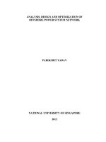
The overall design flow proposed and discussed is illustrated in Fig. 1.1. Each
of the blocks in this diagram will be discussed in more detail in the chapters
to follow.
multiple
word-length
libraries
Simulink
signal
scaling
wordlength
optimization
combined
scaling
and
wordlength
optimization
bit-true
simulator
resource
sharing
(Chapter 6)
synthesis of
structural HDL
error
constraints
(Chapter 3)
(Chapter 5)
vendor
synthesis
completed
design
HDL
libraries
(Chapter 4)
library
cost models
Fig. 1.1. System design flow and relationship between chapters
We begin in Chapter 2 by reviewing some relevant backgroud material,
including a very brief introduction to important nomenclature in DSP, digital
design, and algorithm representation. The key idea here is that in an efficient
hardware implementation of a DSP algorithm, the representation used for each
signal can be different from that used for other signals. Our representation
consists of two parts: the scaling and the word-length. The optimization of
these two parts are covered respectively in Chapters 3 and 4.
1.2 Overview 3
Chapter 3 reviews approaches to determining the peak signal value in a sig-
nal processing system, a fundamental problem when selecting an appropriate
fixed precision representation for signals.
Chapter 4 introduces and formalizes the idea of a multiple word-length im-
plementation. An analytic noise model is described for the modelling of signal
truncation noise. Techniques are then introduced to optimize the word-lengths
of the variables in an algorithm in order to achieve a minimal implementation
area while satisfying constraints on output signal quality. After an analysis
of the nature of the constraint space in such an optimization, we introduce
a heuristic algorithm to address this problem. An extension to the method
is presented for nonlinear systems containing differentiable nonlinear com-
ponents, and results are presented illustrating the advantages of the methods
described for area, speed, and power consumption.
Chapter 5 continues the above discussion, widening the scope to include
the ability to predict the severity of overflow-induced errors. This is exploited
by the proposed combined word-length and scaling optimization algorithm in
order to automate the design of saturation arithmetic systems.
Chapter 6 addresses the implications of the proposed multiple word-length
scheme for the problem of architectural synthesis. The chapter starts by high-
lighting the differences between architectural synthesis for multiple word-
length systems and the standard architectural synthesis problems of schedul-
ing, resource allocation, and resource binding. Two methods to allow the shar-
ing of arithmetic resources between multiple word-length operations are then
proposed, one optimal and one heuristic.
Notation will be introduced in the book as required. For convenience, some
basic notations required throughout the book are provided in Appendix A,
p. 151. Some of the technical terms used in the book are also described in
the glossary, p. 153. In addition, it should be noted that for ease of reading
the box symbol: is used throughout this book to denote the end of an
example, definition, problem, or claim.
This page intentionally left blank
2
Background
This chapter provides some of the necessary background required for the rest
of this book. In particular, since this book is likely to be of interest both
to DSP engineers and digital designers, a basic introduction to the essential
nomenclature within each of these fields is provided, with references to further
material as required.
Section 2.1 introduces microprocessors and field-programmable gate ar-
rays. Section 2.2 then covers the discrete-time description of signals using
the z-transform. Finally, Section 2.3 presents the representation of DSP al-
gorithms using computation graphs.
2.1 Digital Design for DSP Engineers
2.1.1 Micropro cessors vs. Digital Design
One of the first options faced by the designer of a digital signal processing
system is whether that system should be implemented in hardware or soft-
ware. A software implementation forms an attractive possibility, due to the
mature state of compiler technology, and the number of good software en-
gineers available. In addition microprocessors are mass-produced devices and
therefore tend to be reasonably inexpensive. A major drawback of a micro-
processor implementation of DSP algorithms is the computational throughput
achievable. Many DSP algorithms are highly parallelizable, and could benefit
significantly from more fine-grain parallelism than that available with gen-
eral purpose microprocessors. In response to this acknowledged drawback,
general purpose microprocessor manufacturers have introduced extra single-
instruction multiple-data (SIMD) instructions targetting DSP such as the
Intel MMX instruction set [PW96] and Sun’s VIS instruction set [TONH96].
In addition, there are microprocessors specialized entirely for DSP such as the
well-known Texas Instruments DSPs [TI]. Both of these implementations al-
low higher throughput than that achievable with a general purpose processor,
but there is still a significant limit to the throughput achievable.
6 2 Background
The alternative to a microprocessor implementation is to implement the
algorithm in custom digital hardware. This approach brings dividends in the
form of speed and power consumption, but suffers from a lack of mature
high-level design tools. In digital design, the industrial state of the art is
register-transfer level (RTL) synthesis [IEE99, DC]. This form of design in-
volves explicitly specifying the cycle-by-cycle timing of the circuit and the
word-length of each signal within the circuit. The architecture must then be
encoded using a mixture of data path and finite state machine constructs. The
approaches outlined in this book allow the production of RTL-synthesizable
code directly from a specification format more suitable to the DSP application
domain.
2.1.2 The Field-Programmable Gate Array
There are two main drawbacks to designing an application-specific integrated
circuit (ASICs) for a DSP application: money and time. The production of
state of the art ASICs is now a very expensive process, which can only real-
istically be entertained if the market for the device can be counted in millions
of units. In addition, ASICs need a very time consuming test process before
manufacture, as ‘bug fixes’ cannot be created easily, if at all.
The Field-Programmable Gate Array (FPGA) can overcome both these
problems. The FPGA is a programmable hardware device. It is mass-produced,
and therefore can be bought reasonably inexpensively, and its programmabil-
ity allows testing in-situ. The FPGA can trace its roots from programmable
logic devices (PLDs) such as PLAs and PALs, which have been readily avail-
able since the 1980s. Originally, such devices were used to replace discrete
logic series in order to minimize the number of discrete devices used on a
printed circuit board. However the density of today’s FPGAs allows a single
chip to replace several million gates [Xil03]. Under these circumstances, using
FPGAs rather than ASICs for computation has become a reality.
There are a range of modern FPGA architectures on offer, consisting of
several basic elements. All such architectures contain the 4-input lookup table
(4LUT or simply LUT) as the basic logic element. By configuring the data
held in each of these small LUTs, and by configuring the way in which they
are connected, a general circuit can be implemented. More recently, there
has been a move towards heterogeneous architectures: modern FPGA devices
such as Xilinx Virtex also contain embedded RAM blocks within the array
of LUTs, Virtex II adds discrete multiplier blocks, and Virtex II pro [Xil03]
adds PowerPC processor cores.
Although many of the approaches described in this book can be applied
equally to ASIC and FPGA-based designs, it is our belief that programmable
logic design will continue to increase its share of the market in DSP applic-
ations. For this reason, throughout this book, we have reported results from
these methods when applied to FPGAs based on 4LUTs.
2.1 Digital Design for DSP Engineers 7
2.1.3 Arithmetic on FPGAs
Two arithmetic operations together dominate DSP algorithms: multiplication
and addition. For this reason, we shall take the opportunity to consider how
multiplication and addition are implemented in FPGA architectures. A basic
understanding of the architectural issues involved in designing adders and
multipliers is key to understanding the area models derived in later chapters
of this book.
Many hardware architectures have been proposed in the past for fast ad-
dition. As well as the simple ripple-carry approach, these include carry-look-
ahead, conditional sum, carry-select, and carry-skip addition [Kor02]. While
the ASIC designer typically has a wide choice of adder implementations, most
modern FPGAs have been designed to support fast ripple-carry addition. This
means that often, ‘fast’ addition techniques are actually slower than ripple-
carry in practice. For this reason, we restrict ourselves to ripple carry addition.
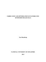
Fig. 2.1 shows a portion of the Virtex II ‘slice’ [Xil03], the basic logic unit
within the Virtex II FPGA. As well as containing two standard 4LUTs, the
slice contains dedicated multiplexers and XOR gates. By using the LUT to
generate the ‘carry propagate’ select signal of the multiplexer, a two-bit adder
can be implemented within a single slice.
4LUT 4LUT
carry
in
carry
out
adder inputs
adder outputs
Fig. 2.1. A Virtex II slice configured as a 2-bit adder
8 2 Background
In hardware arithmetic design, it is usual to separate the two cases of
multiplier design: when one operand is a constant, and when both operands
may vary. In the former case, there are many opportunities for reducing the
hardware cost and increasing the hardware speed compared to the latter case.
A constant-coefficient multiplication can be re-coded as a sum of shifted ver-
sions of the input, and common sub-expression elimination techniques can be
applied to obtain an efficient implementation in terms of adders alone [Par99]
(since shifting is free in hardware). General multiplication can be performed
by adding partial products, and general multipliers essentially differ in the
ways they accumulate such partial products. The Xilinx Virtex II slice, as
well as containing a dedicated XOR gate for addition, also contains a dedic-
ated AND gate, which can be used to calculate the partial products, allowing
the 4LUTs in a slice to be used for their accumulation.
2.2 DSP for Digital Designers
A signal can be thought of as a variable that conveys information. Often
a signal is one dimensional, such as speech, or two dimensional, such as an
image. In modern communication and computation, such signals are often
stored digitally. It is a common requirement to process such a signal in order
to highlight or supress something of interest within it. For example, we may
wish to remove noise from a speech signal, or we may wish to simply estimate
the spectrum of that signal.
By convention, the value of a discrete-time signal x can be represented by a
sequence x[n]. The index n corresponds to a multiple of the sampling period T ,
thus x[n] represents the value of the signal at time nT .Thez transform (2.1)
is a widely used tool in the analysis and processing of such signals.
X(z)=
+∞
n=−∞
x[n]z
−n
(2.1)
The z transform is a linear transform, since if X
1
(z) is the transform of
x
1
[n]andX
2
(z) is the transform of x
2
[n], then αX
1
(z)+βX
2
(z)isthetrans-
form of αx
1
[n]+βx
2
[n] for any real α, β. Perhaps the most useful property of
the z transform for our purposes is its relationship to the convolution oper-
ation. The output y[n] of any linear time-invariant (LTI) system with input
x[n] is given by (2.2), for some sequence h[n].
y[n]=
+∞
k=−∞
h[k]x[n −k] (2.2)
Here h[n] is referred to as the impulse response of the LTI system, and is
a fixed property of the system itself. The z transformed equivalent of (2.2),
where X(z)isthez transform of the sequence x[n], Y (z)isthez transform
2.3 Computation Graphs 9
of the sequence y[n]andH(z)isthez transform of the sequence h[n], is given
by (2.3). In these circumstances, H(z) is referred to as the transfer function.
Y (z)=H(z)X(z) (2.3)
For the LTI systems discussed in this book, the system transfer function
H(z) takes the rational form shown in (2.4). Under these circumstances, the
values {z
1
,z
2
, ,z
m
} are referred to as the zeros of the transfer function and
the values {p
1
,p
2
, ,p
n
} are referred to as the poles of the transfer function.
H(z)=K
(z
−1
− z
−1
1
)(z
−1
− z
−1
2
) (z
−1
− z
−1
m
)
(z
−1
− p
−1
1
)(z
−1
− p
−1
2
) (z
−1
− p
−1
n
)
(2.4)
2.3 Computation Graphs
Synchronous Data Flow (SDF) is a widely used paradigm for the representa-
tion of digital signal processing systems [LM87b], and underpins several com-
merical tools such as Simulink from The MathWorks [SIM]. A simple example
diagram from Simulink is shown in Fig. 2.2. Such a diagram is intuitive as
a form of data-flow graph, a concept we shall formalize shortly. Each node
represents an operation, and conceptually a node is ready to execute, or ‘fire’,
if enough data are present on all its incoming edges.
Fig. 2.2. A simple Simulink block diagram
In some chapters, special mention will be made of linear time invariant
(LTI) systems. Individual computations in an LTI system can only be one of
several types: constant coefficient multiplication, unit-sample delay, addition,
or branch (fork). Of course the representation of an LTI system can be of a
10 2 Background
hierarchical nature, in terms of other LTI systems, but each leaf node of any
such representation must have one of these four types. A flattened LTI rep-
resentation forms the starting point for many of the optimization techniques
described.
We will discuss the representation of LTI systems, on the understanding
that for differentiable nonlinear systems, used in Chapter 4, the representation
is identical with the generalization that nodes can form any differentiable
function of their inputs.
The representation used is referred to as a computation graph (Defini-
tion 2.1). A computation graph is a specialization of the data-flow graphs of
Lee et al. [LM87b].
Definition 2.1. A computation graph G(V,S) is the formal representation of
an algorithm. V is a set of graph nodes, each representing an atomic computa-
tion or input/output port, and S ⊂ V ×V is a set of directed edges representing
the data flow. An element of S is referred to as a signal.ThesetS must satisfy
the constraints on indegree and outdegree given in Table 2.1 for LTI nodes.
The type of an atomic computation v ∈ V is given by type(v) (2.5). Further,
if V
G
denotes the subset of V with elements of gain type, then coef : V
G
→ R
is a function mapping the gain node to its coefficient.
type : V →{inport, outport, add, gain, delay, fork} (2.5)
Table 2.1. Degrees of nodes in a computation graph
type(v) indegree(v) outdegree(v)
inport 0 1
outport 1 0
add 2 1
delay 1 1
gain 1 1
fork 1 ≥ 2
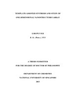
Often it will be useful to visualize a computation graph using a graphical
representation, as shown in Fig. 2.3. Adders, constant coefficient multipliers
and unit sample delays are represented using different shapes. The coefficient
of a gain node can be shown inside the triangle corresponding to that node.
Edges are represented by arrows indicating the direction of data flow. Fork
nodes are implicit in the branching of arrows. inport and outport nodes
are also implicitly represented, and usually labelled with the input and output
names, x[t]andy[t] respectively in this example.
2.3 Computation Graphs 11
x[t] y[t]
+
(b) an example computation graph
+
z
-1
z
-1
ADD GAIN DELAY FORK
(a) some nodes in a computation graph
COEF
Fig. 2.3. The graphical representation of a computation graph
Definition 2.1 is sufficiently general to allow any multiple input, multiple
output (MIMO) LTI system to be modelled. Such systems include operations
such as FIR and IIR filtering, Discrete Cosine Transforms (DCT) and RGB
to YCrCb conversion. For a computation to provide some useful work, its
result must be in some way influenced by primary external inputs to the sys-
tem. In addition, there is no reason to perform a computation whose result
cannot influence external outputs. These observations lead to the definition
of a well-connected computation graph (Definition 2.2). The computability
property (Definition 2.4) for systems containing loops (Definition 2.3) is also
introduced below. These definitions become useful when analyzing the proper-
ties of certain algorithms operating on computation graphs. For readers from
a computer science background, the definition of a recursive system (Defin-
ition 2.3) should be noted. This is the standard DSP definition of the term
which differs from the software engineering usage.
Definition 2.2. A computation graph G(V,S)iswell-connected iff (a) there
exists at least one directed path from at least one node of type inport to
each node v ∈ V and (b) there exists at least one directed path from each
node in v ∈ V to at least one node of type outport.
Definition 2.3. A loop is a directed cycle (closed path) in a computation
graph G(V, S). The loop body is the set of all vertices V
1
⊂ V in the loop. A
computation graph containing at least one loop is said to describe a recursive
system.
12 2 Background
Definition 2.4. A computation graph G is computable iff there is at least one
node of type delay contained within the loop body of each loop in G.
2.4 The Multiple Word-Length Paradigm
Throughout this book, we will make use of a number representation known
as the multiple word-length paradigm [CCL01b]. The multiple word-length
paradigm can best be introduced by comparison to more traditional fixed-
point and floating-point implementations. DSP processors often use fixed-
point number representations, as this leads to area and power efficient imple-
mentations, often as well as higher throughput than the floating-point altern-
ative [IO96]. Each two’s complement signal j ∈ S in a multiple word-length
implementation of computation graph G(V,S), has two parameters n
j
and p
j
,
as illustrated in Fig. 2.4(a). The parameter n
j
represents the number of bits
in the representation of the signal (excluding the sign bit), and the parameter
p
j
represents the displacement of the binary point from the LSB side of the
sign bit towards the least-significant bit (LSB). Note that there are no restric-
tions on p
j
; the binary point could lie outside the number representation, i.e.
p
j
< 0orp
j
>n
j
.
(c)
(n,v(t))
(n,w(t)) (n,x(t))
+
(n,z(t))
(d)
(n,0)
(n,0) (n,0)
+
(n,0)
(b)
(a,v)
(b,w) (c,x)
+
(d,y)
p
S
n
(a)
(n,0)
(e,z)
(n,y(t))
Fig. 2.4. The Multiple Word-Length Paradigm: (a) signal parameters (‘s’ indicates
sign bit), (b) fixed-point, (c) floating-point, (d) multiple word-length
A simple fixed-point implementation is illustrated in Fig. 2.4(b). Each
signal j in this block diagram representing a recursive DSP data-flow, is an-
notated with a tuple (n
j
,p
j
) showing the word-length n
j
and scaling p
j
of the
signal. In this implementation, all signals have the same word-length and scal-
ing, although shift operations are often incorporated in fixed-point designs,
in order to provide an element of scaling control [KKS98]. Fig. 2.4(c) shows a
standard floating-point implementation, where the scaling of each signal is a
function of time.