Programmable logic controllers 5ed P2
Bạn đang xem bản rút gọn của tài liệu. Xem và tải ngay bản đầy đủ của tài liệu tại đây (1.13 MB, 50 trang )
There are two basic forms of stepper motor: the permanent magnet type, with a permanent
magnet rotor, and the variable reluctance type, with a soft steel rotor. There is also a hybrid
form combining both the permanent magnet and variable reluctance types. The most common
type is the permanent magnet form.
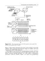
Figure 2.36 shows the basic elements of the permanent magnet type with two pairs of stator
poles. Each pole is activated by a current being passed through the appropriate field winding,
the coils being such that opposite poles are produced on opposite coils. The current is
supplied from a DC source to the windings through switches. With the currents switched
through the coils such that the poles are as shown in Figure 2.36, the rotor will move to line
up with the next pair of poles and stop there. This would be a rotation of 90
. If the current is
then switched so that the polarities are reversed, the rotor will move a step to line up with the
next pair of poles, at angle 180
, and stop there. The polarities associated with each step are
as follows:
Motor
Pulley
wheel
Object
positioned
Figure 2.35: Linear positioning.
S
S
N
N
Pole 1 Pole 3
Pole 4
Pole 2
S
N
S
S
N
N
S
N
S
S
N
N
S
S
S
N
N
S
N
S
S
N
N
S
N
N
1
2
3
4
1, 2, 3 and 4 show the positions of
the magnet rotor as the coils are
energized in different directions
Figure 2.36: The basic principles of the permanent magnet stepper motor
(2-phase) with 90
steps.
www.newnespress.com
46 Chapter 2
Step Pole 1 Pole 2 Pole 3 Pole 4
1 North South South North
2 South North South North
3 South North North South
4 North South North South
5 Repeat of steps 1 to 4
Thus in this case there are four possible rotor positions: 0
,90
, 180
, and 270
.
Figure 2.37 shows the basic principle of the variable reluctance type. The rotor is made of
soft steel and has a number of teeth, the number being less than the number of poles on the
stator. The stator has pairs of poles, each pair of which is activated and made into an
electromagnet by a current being passed through the coils wrapped round it. When one pair
of poles is activated, a magnetic field is produced that attracts the nearest pair of rotor teeth
so that the teeth and poles line up. This is termed the position of minimum reluctance.By
then switching the current to the next pair of poles, the rotor can be made to rotate to line up
with those poles. Thus by sequentially switching the current from one pair of poles to the
next, the rotor can be made to rotate in steps.
There is another version of the stepper motor—the hybrid stepper. This version combines
features of both the permanent magnet and variable reluctance motors. Hybrid steppers have
a permanent magnet rotor encased in iron caps that are cut to have teeth. The rotor sets itself
in the minimum reluctance position when a pair of stator coils are energized.
The following are some of the terms commonly used in specifying stepper motors:
•
Phase. This term refers to the number of independent windings on the stator. Two-phase
motors tend to be used in light-duty applications, three-phase motors tend to be variable
reluctance steppers, and four-phase motors tend to be used for higher-power applications.
This pair of poles
energized by current
being switched to them
Rotor
N
S
Stator
N
S
Rotor lines
up with
these poles
N
S
Rotor lines
up with
these poles
Figure 2.37: The principle of the variable reluctance stepper motor.
www.newnespress.com
Input/Output Devices 47
•
Step angle. This is the angle through which the rotor rotates for one switching change for
the stator coils.
•
Holding torque. This is the maximum torque that can be applied to a powered motor
without moving it from its rest position and causing spindle rotation.
•
Pull-in torque. This is the maximum torque against which a motor will start, for a given
pulse rate, and reach synchronism without losing a step.
•
Pull-out torque. This is the maximum torque that can be applied to a motor, running at a
given stepping rate, without losing synchronism.
•
Pull-in rate. This is the maximum switching rate at which a loaded motor can start
without losing a step.
•
Pull-out rate. This is the switching rate at which a loaded motor will remain in
synchronism as the switching rate is reduced.
•
Slew range. This is the range of switching rates between pull-in and pull-out within
which the motor runs in synchronism but cannot start up or reverse.
To drive a stepper motor so that it proceeds step by step to provide rotation requires each pair
of stator coils to be switched on and off in the required sequence when the input is a sequence
of pulses (Figure 2.38). Driver circuits are available to give the correct sequencing.
Figure 2.39 shows an example: the SAA 1027 for a four-phase unipolar stepper. Motors are
termed unipolar if they are wired so that the current can flow in only one direction through
any particular motor terminal; they’re called bipolar if the current can flow in either direction
through any particular motor terminal. The stepper motor will rotate through one step each
time the trigger input goes from low to high. The motor runs clockwise when the rotation
input is low and anticlockwise when high. When the set pin is made low, the output resets. In
a control system, these input pulses might be supplied by a microprocessor.
Time
Input
pulses
Pulse for
1st coil
Pulse for
2nd coil
Pulse for
3rd coil
Pulse for
4th coil
Time
Inputs to coils
Figure 2.38: Input and outputs of the drive system.
www.newnespress.com
48 Chapter 2
2.3 Examples of Applications
The following are some examples of control systems designed to illustrate the use of a range
of input and output devices.
2.3.1 A Conveyor Belt
Consider a conveyor belt that is to be used to transport goods from a loading machine to a
packaging area (Figure 2.40). When an item is loaded onto the conveyor belt, a contact
switch might be used to indicate that the item is on the belt and to start the conveyor motor.
The motor then has to keep running until the item reaches the far end of the conveyor and
falls off into the packaging area. When it does this, a switch might be activated that has the
effect of switching off the conveyor motor. The motor is then to remain off until the next
item is loaded onto the belt. Thus the inputs to a PLC controlling the conveyor are from two
switches and the output is to a motor.
2.3.2 A Lift
Consider a simple goods lift to move items from one level to another. For example, it might
lift bricks from the ground level to the height where some bricklayers are working. The lift is
Loading
Packaging
Switch Switch
Figure 2.40: Conveyor.
512
6
8
9
11
15
3
2
14 4 13
SAA1027
Stepper motor with
its four stator coils
Supply voltage +12 V
Set
Rotation
Trigger
Brown
Black
Green
Yellow
Red
Red
Figure 2.39: Driver circuit connections with the integrated circuit SAA1027.
www.newnespress.com
Input/Output Devices 49
to move upward when a push button is pressed at the ground level to send the lift upward
or a push button is pressed at the upper level to request the lift to move upward, but in
both cases there is a condition that has to be met that a limit switch indicates that the access
gate to the lift platform is closed. The lift is to move downward when a push button is
pressed at the upper level to send the lift downward or a push button is pressed at the
lower level to request the lift to move downward, but in both cases there is a condition
that has to be met that a limit switch indicates that the access gate to the lift platform is
closed. Thus the inputs to the control system are electrical on/off signals from push button
switches and limit switches. The output from the control system is the signal to control
the motor.
2.3.3 A Robot Control System
Figure 2.41 shows how directional control valves can be used for a control system of a
robot. When there is an input to solenoid A of valve 1, the piston moves to the right and
causes the gripper to close. If solenoid B is energized with A deenergized, the piston
moves to the left and the gripper opens. When both solenoids are deenergized, no air passes
to either side of the piston in the cylinder and the piston keeps its position without change.
Likewise, inputs to the solenoids of valve 2 are used to extend or retract the arm. Inputs to
the solenoids of valve 3 are used to move the arm up or down. Inputs to the solenoids of
valve 4 are used to rotate the base in either a clockwise or anticlockwise direction.
2.3.4 Liquid-Level Monitoring
Figure 2.42 shows a method that could be used to give an on/off signal when the liquid in a
container reaches a critical level. A magnetic float, a ring circling the sensor probe, falls as
the liquid level falls and opens a reed switch when the critical level is reached. The reed
switch is in series with a 39 O resistor so that this is switched in parallel with a 1 kO resistor
by the action of the reed switch. Opening the reed switch thus increases the resistance from
about 37 O to 1 kO. Such a resistance change can be transformed by signal conditioning to
give suitable on/off signals.
2.3.5 Packages on Conveyor Belt Systems
In some situations, the requirement is to check whether there is a nontransparent item on the
belt at a particular position. This can be done using a light emitter on one side of the belt and
a photoelectric sensor on the other, there then being an interruption of the light beam when
the item is at the required position. If the item had been transparent, such as a bottle, the
photoelectric sensor might have been positioned to pick up reflected light to determine when
the item is in the required position.
www.newnespress.com
50 Chapter 2
Summary
The term sensor refers to an input device that provides a usable output in response to a
specified input. The term transducer is generally used for a device that converts a signal from
one form to a different physical form.
Open/close gripper
Valve 1
Extend/retract arm
Valve 2
Up/down arm
Valve 3
Clockwise/anticlockwise base rotation
Valve 4
Extend/retract
Open/close
Up/down
Rotate
clockwise/anticlockwise
A
A
A
A
B
B
B
B
Figure 2.41: Robot controls.
www.newnespress.com
Input/Output Devices 51
Common terms used to specify the performance of sensors are as follows: Accuracy is the
extent to which the value indicated by a measurement system or element might be wrong.
Error is the difference between the result of a measurement and the true value. Nonlinearity
error is the error that occurs as a result of assuming a linear relationship between input and
output. Hysteresis error is the difference in output given for the same measured quantity
according to whether that value was reached by a continuously increasing change or a
continuously decreasing change. Range consists of the limits between which an input can
vary. Response time is the time that elapses after the input is abruptly increased from zero to
a constant value up to the time it reaches some specified percentage of the steady-state value.
Sensitivity indicates how much the output changes when the quantity being measured changes
by a given amount. Stability is a system’s ability to give the same output for a given input
over a period of time. Repeatability is a system’s ability to give the same value for repeated
measurements of the same quantity. Reliability is the probability that a system will operate up
to an agreed level of performance.
Commonly used sensors are mechanical switches; proximity switches, which may be eddy
current, reed, capacitive or inductive; photoelectric, which may be transmissive or reflective
types; encoders that give a digital output as a result of angular or linear displacement,
incremental encoders measuring angular displacement and absolute encoders giving a binary
Magnetic float
Float stop
39
1 k
Reed switch
Liquid
Sensor probe
Ω
Ω
Figure 2.42: Liquid-level monitoring.
www.newnespress.com
52 Chapter 2
output that uniquely defines each angular position; temperature sensors such as bimetallic
strips, resistive temperature detectors, thermistors, thermodiodes, thermotransistors, or
thermocouples; position and displacement sensors such as potentiometers, LVDTs, and
capacitive displacement sensors; strain gauges, which give a resistance change when
strained; pressure sensors such as diaphragm gauges; liquid-level detectors involving
pressure gauges or floats; and fluid flow meters such as the orifice flow meter.
Commonly used output devices include relays, directional control valves with cylinders, DC
motors, and stepper motors.
Problems
Problems 1 through 14 have four answer options: A, B, C, or D. Choose the correct answer
from the answer options.
1. Decide whether each of these statements is true (T) or false (F). A limit switch:
(i) Can be used to detect the presence of a moving part.
(ii) Is activated by contacts making or breaking an electrical circuit.
A. (i) T (ii) T
B. (i) T (ii) F
C. (i) F (ii) T
D. (i) F (ii) F
2. Decide whether each of these statements is true (T) or false (F). A thermistor is a
temperature sensor that gives resistance changes that are:
(i) A nonlinear function of temperature.
(ii) Large for comparatively small temperature changes.
A. (i) T (ii) T
B. (i) T (ii) F
C. (i) F (ii) T
D. (i) F (ii) F
3. A diaphragm pressure sensor is required to give a measure of the gauge pressure present
in a system. Such a sensor will need to have a diaphragm with:
A. A vacuum on one side.
B. One side open to the atmosphere.
C. The pressure applied to both sides.
D. A controlled adjustable pressure applied to one side.
4. The change in resistance of an electrical resistance strain gauge with a gauge factor of 2.0
and resistance 100 O when subject to a strain of 0.001 is:
A. 0.0002 O
B. 0.002 O
www.newnespress.com
Input/Output Devices 53
C. 0.02 O
D. 0.2 O
5. An incremental shaft encoder gives an output that is a direct measure of:
A. The diameter of the shaft.
B. The change in diameter of the shaft.
C. The change in angular position of the shaft.
D. The absolute angular position of the shaft.
6. Decide whether each of these statements is true (T) or false (F). Input devices that give
an analog input for displacement include a:
(i) Linear potentiometer.
(ii) Linear variable differential transformer.
A. (i) T (ii) T
B. (i) T (ii) F
C. (i) F (ii) T
D. (i) F (ii) F
Problems 7 and 8 refer to Figure 2.43, which shows the symbol for a directional valve.
7. Decide whether each of these statements is true (T) or false (F). The valve has:
(i) 4 ports
(ii) 2 positions
A. (i) T (ii) T
B. (i) T (ii) F
C. (i) F (ii) T
D. (i) F (ii) F
8. Decide whether each of these statements is true (T) or false (F). In the control positions:
(i) A is connected to T and P to B.
(ii) P is connected to A and B to T.
A. (i) T (ii) T
B. (i) T (ii) F
C. (i) F (ii) T
D. (i) F (ii) F
AB
PT
Figure 2.43: Diagram for Problems 7 and 8.
www.newnespress.com
54 Chapter 2
9. For the arrangement shown in Figure 2.44, decide whether each of these statements is
true (T) or false (F).
(i) When a current passes through the solenoid, the cylinder extends.
(ii) When the current ceases, the cylinder remains extended.
A. (i) T (ii) T
B. (i) T (ii) F
C. (i) F (ii) T
D. (i) F (ii) F
10. For the arrangement shown in Figure 2.45, decide whether each of these statements is
true (T) or false (F).
(i) When solenoid A is energized, the cylinder extends.
(ii) When solenoid B is energized, the cylinder extends.
A. (i) T (ii) T
B. (i) T (ii) F
C. (i) F (ii) T
D. (i) F (ii) F
Figure 2.44: Diagram for Problem 9.
BA
Figure 2.45: Diagram for Problem 10.
www.newnespress.com
Input/Output Devices 55
11. For the two 3/2 valves shown in Figure 2.46, decide whether each of these statements is
true (T) or false (F).
(i) When the solenoid in valve 1 is energized, A is vented.
(ii) When the solenoid in valve 2 is energized, A is vented.
A. (i) T (ii) T
B. (i) T (ii) F
C. (i) F (ii) T
D. (i) F (ii) F
12. Decide whether each of these statements is true (T) or false (F). A stepper motor has a
step angle of 1.8
. This means that:
(i) Each pulse input to the motor rotates the motor shaft by 1.8
.
(ii) The motor shaft takes 1 s to rotate through 1.8
.
A. (i) T (ii) T
B. (i) T (ii) F
C. (i) F (ii) T
D. (i) F (ii) F
13. A stepper motor has a step angle of 7.5
. The digital input rate required to produce a
rotation of 10 rev/s is:
A. 48 pulses per second
B. 75 pulses per second
C. 480 pulses per second
D. 750 pulses per second
14. Decide whether each of these statements is true (T) or false (F). A proximity switch is
required for detecting the presence of a nonmetallic object. Types of switches that might
be suitable are:
(i) Eddy current type.
(ii) Capacitive type.
A. (i) T (ii) T
B. (i) T (ii) F
1
2
A
A
Figure 2.46: Diagram for Problem 11.
www.newnespress.com
56 Chapter 2
C. (i) F (ii) T
D. (i) F (ii) F
15. Explain the operation of the following input devices, stating the form of the signal being
sensed and the output: (a) reed switch, (b) incremental shaft encoder, (c) photoelectric
transmissive switch, (d) diaphragm pressure switch.
16. Explain how the on/off operation and direction of a DC motor can be controlled by
switches.
17. Explain the principle of the stepper motor and state the different types available.
18. Select sensors that might be suitable for the following applications: (a) counting boxes
moving along a conveyor belt, (b) verifying the level of milk in a plastic bottle
moving along a conveyor belt, (c) determining when the piston in a cylinder has reached
a particular point in its extension; (d) determining when a metal plate has reached the
right position under a tool.
19. The following is part of the specification of a stepper motor. Explain the significance of
the terms: phases 4, step angle 7.5
, current per phase 130 mA, resistance per phase 94 O ,
inductance per phase 43 mH, suitable driver SAA1027.
20. Suggest a way by which a spindle could be controlled to position a mechanism at 5
intervals.
21. A range of opaque bottles of various sizes moves along a conveyor belt. Suggest a
method that could be used to (a) detect the different sizes and (b) push bottles off the
belt.
Lookup Tasks
22. Look up the specifications of thermistors and select one that might be suitable for
monitoring temperatures of about 40
C.
23. Look up the specification of the MPX100AP pressure sensor and write an outline of its
possible use and capabilities.
24. Look up the specification of the LM3911N integrated temperature sensor and write an
outline of its possible use and capabilities.
www.newnespress.com
Input/Output Devices 57
CHAPTER 3
Digital Systems
Digital systems work with inputs, which are essentially just off/on signals, with the two
signal levels represented by 0 and 1. These are termed binary digits. The number system
used for everyday calculations is the denary or decimal system. This is based on the use
of 10 digits: 0, 1, 2, 3, 4, 5, 6, 7, 8, 9. With a number represented by this system, the
digit position in the number indicates the weight attached to each digit, the weight
increasing by a factor of 10 as we proceed from right to left. Hence we have:
10
3
10
2
10
1
10
0
Thousands Hundreds Tens Units
Denary 1000 100 10 1
Thus if we have the denary number 1234, we have 1 with a place value of 10
3
, 2 with a place
value of 10
2
, 3 with a place value of 10
1
, and 4 with a place value of 10
0
. Counting can,
however, be done to any base. The denary system is convenient mainly because we have
10 fingers. If we had only two fingers, our system for everyday counting would probably
have been different. Computers, and hence PLC systems, are based on counting in twos
because it is convenient for their systems, their two digits being effectively just the off and on
signals. When working with PLCs, other base number systems are also used; for example,
input and output addresses are often specified using the octal system, that is, base 8.
However, the PLC itself works with binary numbers. In this chapter we take a look at the
various number systems.
We also take an introductory look at logic systems.ACombinational logic systems take
binary inputs and combine them to give a binary output. The relationship between the inputs
and the output can be described by truth tables. With such systems, the output of a particular
combination of inputs is determined only by their state at the instant of time concerned.
However, with sequential logic systems the output is influenced by the history of the past
inputs as well as by the present inputs. Both combinational logic and sequential logic systems
are introduced in this chapter.
©
2009 Elsevier Ltd. All rights reserved.
doi: 10.1016/B978-1-85617-751-1.00003-3
59
3.1 The Binary System
The binary system is based on just two digits: 0 and 1. These are termed binary digits,orbits.
When a number is represented by this system, the digit position in the number indicates the weight
attached to each digit, the weight increasing by a factor of 2 as we proceed from right to left.
2
3
2
2
2
1
2
0
bit 3 bit 2 bit 1 bit 0
Binary 1000 100 10 1
Bit 0 is termed the least significant bit (LSB) and the highest bit in a binary number is termed
the most significant bit (MSB). For example, with the binary number 1010, the LSB is the bit
at the right end of the number (0 in this example). The MSB is the bit at the left end of
the number (1 in this example).
The conversion of a binary number to a denary number involves the addition of the powers of 2
indicated by the place position of a number in the overall number. Thus for the binary number
1010, we have 1 with a place value of 2
3
, 0 with a place value of 2
2
, 1 with a place value of
2
1
, and 0 with a place value of 2
0
, and so the conversion to a denary number is as follows:
2
3
2
2
2
1
2
0
Binary 1 0 1 0
Denary 2
3
¼ 80 2
1
¼ 20
Thus the denary equivalent is 10.
The conversion of a denary number to a binary number involves looking for the appropriate
powers of 2. We can do this by successive divisions by 2, noting the remainders at each
division. Thus with the denary number 31:
31 Ä 2 ¼ 15 remainder 1; this gives the LSB
15 Ä 2 ¼ 7 remainder 1
7 Ä 2 ¼ 3 remainder 1
3 Ä 2 ¼ 1 remainder 1; this gives the MSB
The binary number is 11111. The first division gives the LSB because we have just divided
31 by 2, that is, 2
1
, and found 1 left over for the 2
0
digit. The last division gives the MSB
because the 31 has then been divided by 2 four times, that is, 2
4
, and the remainder is 1.
3.2 Octal and Hexadecimal
Binary numbers are used in computers because the two states represented by 0 and 1 are easy
to deal with in switching circuits, where they can represent off and on. A problem with binary
www.newnespress.com
60 Chapter 3
numbers is that a comparatively small binary number requires a large number of digits. For
example, the denary number 9, which involves just a single digit, requires four digits when
written as the binary number 1001. The denary number 181, involving three digits, is
10110101 in binary form and requires eight digits. For this reason, octal or hexadecimal
numbers are sometimes used to make numbers easier to handle and act as a “halfway house”
between denary numbers and the binary numbers with which computers work. Thus, for
example, Allen-Bradley uses octal numbering in its PLCs for input and output addresses.
3.2.1 Octal System
The octal system is based on eight digits: 0, 1, 2, 3, 4, 5, 6, 7. When a number is
represented by this system, the digit position in the number indicates the weight attached
to each digit, the weighting increasing by a factor of 8 as we proceed from right to left.
Thus we have:
8
3
8
2
8
1
8
0
Octal 1000 100 10 1
To convert denary numbers to octal, we successively divide by 8 and note the remainders.
Thus the denary number 15 divided by 8 gives 1 with remainder 7; thus the denary number
15 is 17 in the octal system. To convert from octal to denary, we multiply the digits by the
power of 8 appropriate to its position in the number. For example, the octal number 365 is
3 Â 8
2
þ 6 Â 8
1
þ 5 Â 8
0
¼ 245. To convert from binary into octal, the binary number is
written in groups of three bits starting with the least significant bit. For example, the binary
number 11010110 would be written as:
11 010 110
Each group is then replaced by the corresponding digit from 0 to 7. For example, the 110
binary number is 6, the 010 is 2, and the 11 is 3. Thus the octal number is 326. As another
example, the binary number 100111010 is:
100 111 010 Binary
472Octal
Octal-to-binary conversion involves converting each octal digit into its 3-bit equivalent.
Thus, for the octal number 21, we have 1 as 001 and 2 as 010:
21Octal number
010 001 Binary number
and so the binary number is 010001.
www.newnespress.com
Digital Systems 61
3.2.2 Hexadecimal System
The hexadecimal system (hex) is based on 16 digits/symbols: 0, 1, 2, 3, 4, 5, 6, 7, 8, 9, A, B,
C, D, E, F. When a number is represented by this system, the digit position in the number
indicates that the weight attached to each digit increases by a factor of 16 as we proceed from
right to left. Thus we have:
16
3
16
2
16
1
16
0
Hex 1000 100 10 1
For example, the decimal number 15 is F in the hexadecimal system. To convert from denary
numbers into hex we successively divide by 16 and note the remainders. Thus the denary
number 156, when divided by 16, gives 9 with remainder 12, and so in hex is 9C. To convert
from hex to denary, we multiply the digits by the power of 16 appropriate to its position in
the number. Thus hex 12 is 1 Â 16
1
þ 2 Â 16
0
¼ 18. To convert binary numbers into
hexadecimal numbers, we group the binary numbers into fours starting from the least
significant number. Thus, for the binary number 1110100110 we have:
11 1010 0110 Binary number
3A6Hex number
For conversion from hex to binary, each hex number is converted to its 4-bit equivalent.
Thus, for the hex number 1D we have 0001 for the 1 and 1101 for the D:
1DHex number
0001 1101 Binary number
Thus the binary number is 0001 1101.
3.3 Binary Coded Decimals
Because the external world tends to deal mainly with numbers in the denary system and
computers with numbers in the binary system, there is always the problem of conversion.
There is, however, no simple link between the position of digits in a denary number and the
position of digits in a binary number. An alternative method that is often used is the binary
coded decimal system (BCD). With this system, each denary digit is coded separately in
binary. For example, the denary number 15 has the 5 converted into the binary number 0101
and the 1 into 0001:
15Denary number
0001 0101 Binary number
www.newnespress.com
62 Chapter 3
to give the number 0001 0101 in BCD. With the BCD system, the largest decimal number
that can be displayed is a 9, and so the four binary digits are 1001.
To convert a BCD number to a denary number, each group of four binary numbers is
separately converted to a denary number. For example, the BCD number 0011 1001 has a
denary number of 3 for 0011 and 9 for 1001, and so the denary number is 39.
0011 1001 BCD number
39Denary number
Numeric data is often entered into PLCs by rotary or thumb-wheel switches with a 0 to 9
range. Thus there may be a bank of such switches, one giving, say, the hundreds, one the
tens, and one the ones. The output from each switch is then converted, independently, into
binary to give the overall result of a binary coded decimal number. Some PLCs have a
function that can be called up to convert such BCD numbers to binary numbers; in other
PLCs it has to be done by programming.
3.4 Numbers in the Binary, Octal, Hex, and BCD Systems
Table 3.1 gives examples of numbers in the denary, binary, octal, hex, and BCD systems.
Table 3.1: Examples of Numbers in Various Systems
Denary Binary Octal Hex BCD
0 00000 0 0 0000 0000
1 00001 1 1 0000 0001
2 00010 2 2 0000 0010
3 00011 3 3 0000 0011
4 00100 4 4 0000 0100
5 00101 5 5 0000 0101
6 00110 6 6 0000 0110
7 00111 7 7 0000 0111
8 01000 10 8 0000 1000
9 01001 11 9 0000 1001
10 01010 12 A 0001 0000
11 01011 13 B 0001 0001
12 01100 14 C 0001 0010
13 01101 15 D 0001 0011
14 01110 16 E 0001 0100
15 01111 17 F 0001 0101
16 10000 20 10 0001 0110
17 10001 21 11 0001 0111
www.newnespress.com
Digital Systems 63
3.5 Binary Arithmetic
Addition of binary numbers uses the following rules:
0 þ 0 ¼ 0
0 þ 1 ¼ 1 þ 0 ¼ 1
1 þ 1 ¼ 10
1 þ 1 þ 1 ¼ 11
Consider the addition of the binary numbers 01110 and 10011.
01110
10011
Sum 100001
For bit 0 in the sum, 0 þ 1 ¼ 1. For bit 1 in the sum, 1 þ 1 ¼ 10, and so we have 0 with
1 carried to the next column. For bit 2 in the sum, 1 þ 0 þ the carried 1 ¼ 10. For bit 3 in the
sum, 1 þ 0 þ the carried 1 ¼ 10. We continue this process through the various bits and
end up with 100001.
Subtraction of binary numbers follows these rules:
0 À 0 ¼ 0
1 À 0 ¼ 1
1 À 1 ¼ 0
When evaluating 0 À 1, a 1 is borrowed from the next column on the left that
contains a 1. The following example illustrates this method with the subtraction of
01110 from 11011:
11011
01110
Difference 01101
For bit 0 we have 1 À 0 ¼ 1. For bit 1 we have 1 À 1 ¼ 0. For bit 2 we have 0 À 1. We thus
borrow 1 from the next column and so have 10 À 1 ¼ 1. For bit 3 we have 0 À 1 (remember,
we borrowed the 1). Again borrowing 1 from the next column, we then have 10 À 1 ¼ 1. For
bit 4 we have 0 À 0 ¼ 0 (remember, we borrowed the 1).
www.newnespress.com
64 Chapter 3
3.5.1 Signed Numbers
The binary numbers considered so far contain no indication as to whether they are negative
or positive and are thus said to be unsigned. Since there is generally a need to handle both
positive and negative numbers, there needs to be some way of distinguishing between them.
This can be done by adding a sign bit. When a number is said to be signed, its MSB is used to
indicate the sign of the number; a 0 is used if the number is positive and a 1 is used if it is
negative. Thus for an 8-bit number we have:
xxxx xxxx
"
Sign bit
When we have a positive number, we write it in the normal way, with a 0 preceding it. Thus a
positive binary number of 10110 is written as 010110. A negative number of 10110 is written
as 110110. However, this is not the most useful way of writing negative numbers for ease of
manipulation by computers.
3.5.2 One’s and Two’s Complements
A more useful way of writing signed negative numbers is to use the two’s complement
method. A binary number has two complements, known as the one’s complement and the
two’s complement. The one’s complement of a binary number is obtained by changing all the
1s in the unsigned number into 0s and the 0s into 1s. Thus if we have the binary number
101101, the one’s complement of it is 010010. The two’s complement is obtained from the
one’s complement by adding 1 to the LSB of the one’s complement. Thus the two’s
complement of 101101 becomes 010011.
When we have a negative number, to obtain the signed two’s complement, we obtain the
two’s complement and then sign it with a 1. Consider the representation of the decimal
number À6 as a signed two’s complement number when the total number of bits is eight. We
first write the binary number for þ 6, that is, 0000110, then obtain the one’s complement of
1111001, add 1 to give 1111010, and finally sign it with a 1 to indicate it is negative. The
result is thus 11111010.
Unsigned binary number when sign ignored 000 0110
One’s complement 111 1001
Add 1 1
Unsigned two’s complement 111 1010
Signed two’s complement 1111 1010
Table 3.2 lists some signed two’s complements for denary numbers, given to 4 bits.
www.newnespress.com
Digital Systems 65
When we have a positive number, we sign the normal binary number with a 0, that is, we
write only negative numbers in the two’s complement form. A consequence of adopting this
method of writing negative and positive numbers is that when we add the signed binary
equivalent of þ4 and –4, that is, 0000 0100 and 111 1100, we obtain (1)0000 0000 and so
zero within the constraints of the number of bits used, the (1) being neglected.
Subtraction of a positive number from a positive number can be considered to be the addition
of a negative number to a positive number. Thus we obtain the signed two’s complement of
the negative number and then add it to the signed positive number. Hence, for the subtraction
of the denary number 6 from the denary number 4, we can consider the problem as being
(þ4) þ (À6). Hence we add the signed positive number to the signed two’s complement for
the negative number.
Binary form of þ4 0000 0100
(À6) as signed two’s complement 1111 1010
Sum 1111 1110
The MSB, that is, the sign, of the outcome is 1 and so the result is negative. This is the 8-bit
signed two’s complement for À2.
If we wanted to add two negative numbers, we would obtain the signed two’s complement
for each number and then add them. Whenever a number is negative, we use the signed two’s
complement; when it’s positive, we use just the signed number.
3.5.3 Floating Point Numbers
Before we discuss floating point numbers, let’s consider fixed point numbers. Fixed point
numbers are numbers for which there is a fixed location of the point separating integers from
fractional numbers. Thus, 15.3 is an example of a denary fixed point number, 1010.1100
an example of a fixed point binary number, and DE.2A an example of a fixed point
hexadecimal number. We have, with the 8-bit binary number, four digits before the binary
point and four digits after it. When two such binary numbers are added by a computing
system, the procedure is to recognize that the fixed point is fixed the same in both numbers,
Table 3.2: Signed Two’s Complements
Denary Number Signed Two’s Complement
À5 1011
À4 1100
À3 1101
À2 1110
À1 1111
www.newnespress.com
66 Chapter 3
so we can ignore it for the addition, carry out the addition of the numbers, and then insert in
the result the binary point in its fixed position. For example, suppose we want to add
0011.1010 and 0110.1000; we drop the binary point to give:
0011 1010 þ 0110 1000 ¼ 1010 0010
Inserting the binary point then gives 1010.0010.
Using fixed points does present problems. If we are concerned with very large or very small
numbers, we could end up with a large number of zeros between the integers and the point,
that is, 0.000 000 000 000 023. For this reason, scientific notation is used for such numbers.
Thus, the above number might be written as 0.23 Â 10
–13
or 2.3 Â 10
–14
or 23 Â 10
–15
.
Likewise, the binary number 0.0000 0111 0010 might be represented as 110010 Â 2
–12
(the 12 would also be in binary format) or 11001.0 Â 2
–11
(the 11 being in binary format).
Such notation is said to have a floating point.
A floating point number is in the form a  r
e
, where a is termed the mantissa, r the radix
or base, and e the exponent or power. With binary numbers the base is understood to be 2,
that is, we have a  2
e
, and when we know we are dealing with binary numbers we need not
store the base with the number. Thus a computing system needs, in addition to storing the
sign, that is, whether positive or negative, to store the mantissa and the exponent.
Because with floating point numbers it is possible to store a number in several different
ways—for example, 0.1 Â 10
2
and 0.01 Â 10
3
—with computing systems such numbers are
normalized. This means that they are all put in the form 0.1 Â r
e
. Thus, with binary numbers
we have 0.1 Â 2
e
; if we had 0.00001001 it would become 0.1001 Â 2
–4
. To take account of
the sign of a binary number, we then add a sign bit of 0 for a positive number and 1 for a
negative number. Thus the number 0.1001 Â 2
–4
becomes 1.1001 Â 2
–4
if negative and
0.1001 Â 2
–4
if positive.
Unlike fixed point numbers, floating point numbers cannot be directly added unless the
exponents are the same. Thus to carry out addition we need to make the exponents the same.
3.6 PLC Data
Most PLCs operate with a 16-bit word, with the term word meaning the group of bits
constituting some information. This allows a positive number in the range 0 to þ65535, that
is, 1111 1111 1111 1111, to be represented, or a signed number in the range –32768 to
þ32767 in two’s complement, the MSB then representing the sign. Such signed numbers are
referred to as integers, with the symbol INT being used with inputs and outputs in programs
of such 16-bit words. The term SINT is used for short integer numbers, for which only
8 bits are used, such numbers giving the range –128 to þ127. The term DINT is used for
www.newnespress.com
Digital Systems 67
double-integer numbers, for which 32 bits are used, such numbers giving the range –2
31
to þ2
31
– 1. LINT is used for long integer numbers, for which 64 bits are used, such
numbers giving the range –2
63
to þ2
63
– 1. Where numbers are not signed, the symbols
UINT, USINT, UDINT, and ULINT are used with integers, short integers, double integers,
and long integers.
Decimal fractions are referred to as real or floating point numbers and are represented by the
symbol REAL for inputs and outputs in programs. These consist of two 16-bit words; so we
might have 1.234567Eþ03 for the number 1.234 567 Â 10
þ3
, the E indicating that the
number that follows is the exponent. The term LREAL is used for long real numbers,in
which 64 bits are used.
The term BOOL is used for Boolean type data, such data being on/off values, that is, 0 or 1,
and thus represented by single bits.
Time duration, such as for the duration of a process, is represented by the IEC standard using
the symbols d for days, h for hours, m for minutes, s for seconds, and ms for milliseconds,
as, for example, T#12d2h5s3ms or TIME#12d2h5s for 12 days, 2 hours, 5 seconds, and
3 milliseconds. Note that # is the symbol used to indicate that what follows is a numerical
quantity.
3.7 Combinational Logic Systems
Consider a system that might be used as an “interlock” to safeguard the operation of a
machine. The machine is to start only if two safety conditions are realized: the workpiece is
in position and the safety guard is in position. The workpiece in position can be regarded as
input A to a system and the safety guard in position as input B (Figure 3.1).
For the input conditions to be expressed in binary form, we require there to be just two
possibilities for each input. In this case, if we phrase the question to be posed of each input
as having a YES or NO answer, we have just two conditions, which we can write as 1 for
YES and 0 for NO. Thus input A can be phrased as follows: “Is the workpiece in position?”
and the answer is YES or NO. Input B can be phrased as: “Is the safeguard in position?” and
the answer is YES or NO. For this system we require there to be an output when input A is 1
and input B is 1. This relationship between the inputs and output can be tabulated as a truth
table showing all the possible combinations of inputs, the combination of which leads to a 1,
that is, YES, output, or a 0, that is, NO, output. Table 3.3 is the truth table for this system.
System
Input A
Output Q
Input B
Figure 3.1: Machine interlock system.
www.newnespress.com
68 Chapter 3
Each input can take only two values, represented by 0 or 1, and are described as two-state
variables or logical variables. The complete system constructed with such variable is termed
a logic system or logic gates. If the output of such a system depends only on the present states
of the inputs, as with the machine “interlock,” it is termed a combinational logic system.
Useful combinational logic systems, which we will meet in Chapter 5, are the AND gate, the
OR gate, the NOT gate, the NAND gate, the NOR gate, and the XOR gate. The machine
“interlock” system is an example of an AND gate in that input A and input B have to be 1 for
the output to be 1.
3.8 Sequential Logic Systems
With a sequential logic system, the present output is influenced by the history of its past
inputs as well as by its present input. This is unlike a combinational logic system, where the
output only depends on the current state of its inputs. A binary counter can be regarded as a
sequential logic system in that the binary output depends on the present input and the sum of
the previous inputs. It thus has a “memory.”
Most sequential systems are based on a small number of sequential logic systems called
bistables, so-called because they have two stable conditions and can be switched from one to
the other by appropriate inputs. Once the circuit has switched, it remains in the other stable
state until another input pulse has been received to force it to return to the original state.
Basically bistables are a memory device; they can “remember” the effect of an input after
the input has been removed.
A latch and a flip-flop, so called because it can, on command, flip into one stable state or flop
back again to the other, are bistables. A latch is triggered by the voltage level applied to its
input, provided that it has been enabled by its clock input being, generally, high. Flip-flops are
devices that change state at either the leading edge or the trailing edge of an enable/clock pulse.
3.8.1 Latches
The clocked D latch has a data input D, outputs Q and
Q, and an enable/clock input CLK
(Figure 3.2). Q is always the complement of
Q. The logical state of the Q output will follow
any changes in the logical state of the D input as long as the clock input remains high. When
Table 3.3: A Truth Table
Input A Input B Output Q
000
100
010
111
www.newnespress.com
Digital Systems 69
the clock input goes low, the logical state of the D input at that moment will be retained
as the Q output, no matter what changes occur at the D input. When the clock input goes
high again, the output Q will again follow any changes in the logical state of the D input.
The latch is said to be transparent when the clock is high.
Truth tables can be drawn for latches, but they must take into account the effect of applying a
pulse on the clock input. For this reason they are often referred to as function tables.
Table 3.4 is the function table for the clocked D latch. Q
þ
is the state of the Q output after a
clock-triggering input.
The clocked SR latch has two input terminals, S for set and R for reset; outputs Q and
Q; and
an enable/clock input CLK (Figure 3.3). Q is always the complement of
Q. When both S
and R are held low, the logical state of the outputs will not change. When S is 1 and R is 0,
the logical state of the output Q will become 1, no matter what its value was before. This
is termed the set operation. If S is 0 and R is 1, the Q output will be 0, whatever its value
was before. This is the reset operation. If both S and R are 1, the operation of the latch is
D
CLK
Q
Q
Figure 3.2: The clocked D latch.
Table 3.4: Clocked D-Latch
CLK D Q Q
þ
0 0 0 0 No change in
output, held at
previous value.
0011
0100
0111
1 0 0 0 Output changes
to new value.
1010
1101
1111
SQ
CLK
Q
R
Figure 3.3: The clocked SR latch.
www.newnespress.com
70 Chapter 3
unpredictable, and so this combination of inputs should not be allowed to occur. Table 3.5
shows the function table.
3.8.2 Flip-Flops
A JK flip-flop has two data input terminals, J and K; a clock input; and two output terminals
Q and
Q(Figure 3.4). A JK flip-flop will change its output state at a clock transition, either at
a leading edge or the trailing edge of the clock pulse. A JK flip-flop always changes state
when J ¼ K ¼ 1 and might be said to toggle. Table 3.6 is the function table.
Summary
The denary number system is based on the use of 10 digits 0, 1, 2, 3, 4, 5, 6, 7, 8, 9.
The binary system is based on just two: 0 and 1. The octal system is based on eight digits:
0, 1, 2, 3, 4, 5, 6, 7. The hexadecimal system is based on the use of 16 digits: 0, 1, 2, 3, 4, 5,
Table 3.5: Clocked SR Latch
CLK S R Q Q
þ
00000Nochange, held.
00011
01000
01011
00100
00111
01100
01111
10000
10011
11001 Set
11011
10100Reset
10110
1 1 1 0 x Indeterminate
1111x
JQ
CLK
Q
K
Figure 3.4: The clocked JK flip-flop.
www.newnespress.com
Digital Systems 71