Programmable logic controllers 5ed P7
Bạn đang xem bản rút gọn của tài liệu. Xem và tải ngay bản đầy đủ của tài liệu tại đây (1.36 MB, 50 trang )
13.4.1 Fault Detection Techniques
The following are some common fault detection techniques:
•
Timing checks. The term watchdog is used for a timing check that is carried out by the
PLC to check that some function has been carried out within the normal time. If the
function is not carried out within the normal time, a fault is assumed to have occurred
and the watchdog timer trips, setting off an alarm and perhaps closing down the PLC.
As part of the internal diagnostics of PLCs, watchdog timers are used to detect faults.
The watchdog timer is preset to a time slightly longer than the scan time would normally
be. It is then set at the beginning of each program scan and, if the cycle time is normal, it
does not time out and is reset at the end of a cycle, ready for the next cycle. However, if
the cycle time is longer than it would normally be, the watchdog timer times out and
indicates that the system has a fault.
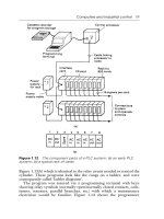
Within a program, additional ladder rungs are often included so that when a function
starts, a timer is started. If the function is completed before the time runs out, the
program continues, but if not, the program uses the jump command to move to a special
set of rungs, which triggers an alarm and perhaps stops the system. Figure 13.16 shows
an example of a watchdog timer that might be used with the movement of a piston in a
cylinder. When the start switch is closed, the solenoid of a valve is energized and causes
the piston in the cylinder to start moving. It also starts the timer. When the piston is fully
extended, it opens a limit switch and stops the timer. If the time taken for the piston to
move and switch off the timer is greater than the preset value used for the timer, the timer
sets off the alarm.
Limit
switch
Solenoid valve
switching pressure
to cylinder
END
Start
Solenoid Limit Timer
Timer Alarm
Solenoid
Figure 13.16: Watchdog timer.
www.newnespress.com
302 Chapter 13
•
Last output set. This technique involves the use of status lamps to indicate the last output
that has been set during a process that has come to a halt. Such lamps are built into the
program so that as each output occurs, a lamp comes on. The lamps that are on thus
indicate which outputs are occurring. The program has to be designed to turn off previous
status lamps and turn on a new status lamp as each new output is turned on. Figure 13.17
illustrates this concept.
Output 0
Output 1
Input 0
Output 0
Input 1
Part of the main proga
m
When input 0 occurs, then
output 0 happens.
When output 0 occurs, then
output 1 will follow when
input 1 occurs. Input 1 will
then switch off output 0.
Input 1
Last output set diagnostic program element
s
Output 0 Timer 0
Timer 0
Relay 0
Output 1
Timer 1
Timer 1 Relay 1
When output 0 occurs, then
timer 0 is set running, e.g. fo
r
0.5 s. As a result relay 0 is
set for that time.
When output 1 occurs, then
timer 1 is set running, e.g. fo
r
0.5 s. As a result relay 1 is
set for that time.
Relay 0
Output 0
Relay 1
Relays
from other outputs
Status
lamp 0
Status
lamp 1Relay 1
Output 1
Relay 0
Relays
from other outputs
When relay 0 on and
latched by output 0,
then status lamp 0
comes on, going off
when output 0 ceases.
When relay 1 on and
latched by output 1,
then status lamp 1
comes on, going off
when output 1 ceases.
Figure 13.17: Last output set diagnostic program.
www.newnespress.com
Designing Systems 303
Such a technique can be cumbersome in a large system with many outputs. In such a
case, the outputs might be grouped into sets and a status lamp used for each set. A
selector switch can then be used within a group to select each output in turn to determine
whether it is on. Figure 13.18 illustrates this idea.
As an illustration of the use of this program to indicate which action occurred last,
Figure 13.19 shows the program that might be used with a pneumatic system operating
cylinders in a sequence. The program indicates at which point in the sequence a fault
occurred, such as a piston sticking, and would be added to the main program used to
sequence the cylinders. Each of the cylinder movements has a light-emitting diode
associated with it, with the last cylinder movement indicated by its LED being
illuminated.
Status lamp 1
Status lamp 2
Output 1
Output 2
Output 3
Output 4
Output 50
Output 51
Output 52
Output 53
Switch 1
Switch 2
a
etc.
etc.
a
b
c
d
b
c
d
Switch 1 in position a
indicates output 1, in
position b output 2, in
position c output 3, etc.
Switch 2 in position a
indicates output 50, in
position b output 51, in
position c output 52, etc.
Figure 13.18: Single status lamp for a group of outputs.
www.newnespress.com
304 Chapter 13
A+ Timer 1
Timer 1 IR 1
B+
Timer 2
Timer 2 IR 2
C+
Timer 3
Timer 3 IR 3
A−
Timer 4
Timer 4 IR 4
B−
Timer 5
Timer 5 IR 5
C−
Timer 6
Timer 6
IR 6
IR 1
LED A+
LED A+
IR 2 IR 3 IR 4 IR 5 IR 6 Reset
IR 1 IR 3 IR 4 IR 5 IR 6 Reset
IR 2
LED B+
LED B+
The output A+ produces a
short duration pulse at
IR 1 as a result of the
timer setting
The output B+ produces a
short duration pulse at
IR 2 as a result of the
timer setting
The output C+ produces a
short duration pulse at
IR 3 as a result of the
timer setting
The output A– produces a
short duration pulse at
IR 4 as a result of the
timer setting
The output B– produces a
short duration pulse at
IR 5 as a result of the
timer setting
The output C– produces a
short duration pulse at
IR 6 as a result of the
timer setting
If A+ output occurs, IR 1 closes
and is latched on. LED A+ is
then on. LED A+ is not on
unless IR 1 closed
If B+ output occurs, IR 2 closes
and is latched on. LED B+ is
then on. LED B+ is not on
unless IR 2 closed
Figure 13.19: Diagnostic program for last cylinder action.
(Continued)
www.newnespress.com
•
Replication. Where there is concern regarding safety in the case of a fault developing,
checks may be constantly used to detect faults. One technique is replication checks,
which involve duplicating, that is, replicating, the PLC system. This could mean that the
system repeats every operation twice and, if it gets the same result, it is assumed that
there is no fault. This procedure can detect transient faults. A more expensive alternative
is to have duplicate PLC systems and compare the results given by the two systems. In
the absence of a fault, the two results should be the same.
•
Expected value checks. Software errors can be detected by checking whether an expected
value is obtained when a specific input occurs. If the expected value is not obtained, a
fault is assumed to be occurring.
13.4.2 Program Storage
Applications programs may be loaded into battery-backed RAM in a PLC. A failure of the
battery supply means a complete loss of the stored programs. An alternative to storing
IR 4 IR 1 IR 2 IR 3 IR 5 IR 6 Reset
IR 1 IR 2 IR 3 IR 4 IR 6 Reset
IR 1 IR 2 IR 3 IR 4 IR 5 Reset
IR 1 IR 2 IR 4 IR 5 IR 6 Reset
LED A–
LED A–
IR 5
IR 6
LED B–
LED B–
LED C–
LED C–
END
If A– output occurs, IR 4 closes
and is latched on. LED A– is
then on. LED A– is not on
unless IR 4 is closed
If B– output occurs, IR 5 closes
and is latched on. LED B– is
then on. LED B– is not on
unless IR 5 is closed
If C– output occurs, IR 6 closes
and is latched on. LED C– is
then on. LED C– is not on
unless IR 6 is closed
IR 3
LED C+
LED C+
If C+ output occurs, IR 3 closes
and is latched on. LED C+ is
then on. LED C+ is not on
unless IR 3 is closed
Figure 13.19 —Cont’d
www.newnespress.com
306 Chapter 13
applications programs in battery-backed RAM is to use EPROM. This form of memory is
secure against the loss of power. Against the possibility of memory failure occurring in
the PLC and loss of the stored application program, a backup copy of each application
program should be kept. If the program has been developed using a computer, the backup
may be on a CD or a hard disk. Otherwise the backup may be on an EPROM cartridge.
The program can then again be downloaded into the PLC without it having to be rewritten.
13.5 System Documentation
The documentation is the main guide used by everyday users, including for troubleshooting
and fault finding with PLCs. It thus needs to be complete and in a form that is easy to follow.
The documentation for a PLC installation should include the following:
•
A description of the plant
•
Specification of the control requirements
•
Details of the programmable logic controller
•
Electrical installation diagrams
•
Lists of all input and output connections
•
Application program with full commentary on what it is achieving
•
Software backups
•
Operating manual, including details of all start up and shut down procedures and alarms
13.5.1 Example of an Industrial Program
The following is an example of the way a program might appear for a real plant controlled by
an Allen-Bradley PLC5; I am grateful to Andrew Parr for supplying it. It illustrates the way a
program file is documented to aid in clarification and the safety and fault indication
procedures that are used. Note that the right-hand power rail has been omitted, which is
allowable in IEC 1131-3.
The program is one of about 40 program files in the complete program, each file
controlling one area of operation and separated by a page break from the next file. The
file that follows controls a bundle-cutting band saw and involves motor controls, desk
lamps, and a small state transition sequence.
Note the rung cross-references, such as [38], below B3/497 in rung 2. These are used to
show that B3/497 originates, for example, in rung 38 in the current program file. Also note
that all instructions are tagged with descriptions and the file is broken down into page
sections. The software allows you to go straight to a function via the page titles.
www.newnespress.com
Designing Systems 307
All the motor starter rungs work in the same way. The PLC energizes the contactor and then
one second later looks for the auxiliary relay (labeled as Aux in the program file) coming
back to say the contactor has energized. If there is a fault that causes the contactor to
deenergize, such as a loss of supply, or a trip or open circuit coil, it causes the PLC to signal a
fault and deenergize the contactor output so that the machine does not spring into life when
the fault is cleared.
The saw normally sits raised clear of the bundle. To cut the bundle, the blade motor has to be
started and the lower push-button pressed (at rung 8). The saw falls under gravity at a fast or
slow speed that is set by hydraulic valves. To raise the saw, a hydraulic pump is started to
pump oil into the saw support cylinders. At any time the saw can be raised, such as to clear
swarf, to what is termed the pause state. Otherwise, cutting continues until the bottom limit is
reached. The saw then is raised to the top limit for the next bundle. A cut can be aborted by
pressing the raise button for two seconds. While a bundle is being cut, it is held by clamp
solenoids.
The final three rungs of the program set the length to be cut. There are two photocells about
20 mm apart on a moveable carriage. These are positioned at the required length. The
operator runs the bundle in until the first is blocked and the second is clear. These control the
long/correct/short desk lamps.
www.newnespress.com
308 Chapter 13
Bundle Cutting Saw
***Saw Cutting Saw Motor
Stacking Machine
Page:00001File #14 Saw Proj: FLATS3 21:08 12/05/02
Saw_Motor
Tripped
l=Tripped
I:032
Saw_Motor
Start_Fault
B3
Saw_Motor
Start_PB
I:030
Saw_Motor
Stop_PB
I:030
Saw_Motor
Available
B3
Saw_Motor
Available
B3
Saw_Blade
Tension_LS
l = Healthy
I:032
Saw_Motor
Contactor
O:034
Saw_Motor
Contactor
O:034
Saw_Motor
Start_Fault
T4:109
Saw_Motor
B3
517
[2]
DN
[1]
11 497
[38]
517
Saw_Motor
Running_Aux
I:032
Saw_Alarms
Accept
B3
Saw_Motor
Start_Fault
B3
(EN)
(DN)
TON
Timer:
Preset: 100
0
Accum:
T4:109
Base (SEC): 0.01
51617517
[2]
10
0
2+ +
+] [
] [ ]/[
+
1
+
+
] [
++
+
] [
]/[ ]/[ ] [
] [ ] [ ] [ +
+
+<
( )
( )
>
>
>
]/[ ( )+
++
+
+
+
+
+
+
Timer On Delay
+
00 01 516
[0]
[1]
03
10
Saw_ESR
Healthy
I:031
Saw_Motor
Start_Motor
www.newnespress.com
Designing Systems 309
Bundle Cutting Saw
Coolant Pump
Stacking Machine
Page:00002File #14 Saw Proj: FLATS3 21:08 12/05/02
Coolant_Pump
l=Tripped
I:032
Coolant_Pump
Select_SW
I:030
Coolant_Pump
Select_SW
I:030
Test_Run
Coolant_Pump
TOF_Timer
T4:110
Coolant Pump
Start_Fault
TON_Timer
T4:111
Coolant_Pump
Start_Fault
B3
Coolant_Pump
Running_Aux
I:032
Saw_Motor &
Coolant_OK
B3
Coolant_Pump
Select_SW
Saw_Motor
Running_Aux
I:032
[6]519
11
++
++
+
++
++
+
+
+
+
++
++
++
++
+++
+
++
++
+
+
+
++
13 496
02
7
6
5
4
3 + ]/[
] [
] [ ] [
]ONS[
] [
] [
] [ ] [
]/[
] [ ]/[
( )
( )
( )
]/[ ] [ ( )
Coolant_Pump
Start_Fault
TON Timer
Coolant_Pump
Contactor
O:034
Saw_Motor
Running_Aux
I:032
Coolant_Pump
Running_Aux
I:032
Saw_Alarms
Accept
B3
Coolant_Pump
Start_Fault
B3
OneShot
B3
12
02
02
520
DN
[4]
11
11
TON
DN
[5]
13 497
[38]
519
519
[6]
17 518
Test_Run
Coolant_Pump
TOF_Timer
TOF
Coolant_Pump
Start_Fault
B3
Coolant_Pump
Available
B3
Saw_ESR
Healthy
I:031
(EN)
(DN)
(EN)
(DN)
Timer:
Preset:
4
4
100
0
Accum:
T4:110
Base (SEC): 1.0
Timer Off Delay
Timer:
Preset:
Accum:
T4:111
Base (SEC): 0.01
Timer On Delay
] [
www.newnespress.com
310 Chapter 13
Bundle Cutting Saw
Coolant Pump
Stacking Machine
Page:00003File #14 Saw Proj: FLATS3
Blank page for future modification
21:08 12/05/02
www.newnespress.com
Designing Systems 311
Bundle Cutting Saw
Saw Cut Sequence Transitions
Stacking Machine
Page:00004File #14 Saw Proj: FLATS3 21:08 12/05/02
State_0
Ready_for
Start
B3
Saw_Motor_&
Coolant_OK
B3
500
[15]
8+
9+ + +
] [ ] [
] [
10 + ] [ ] [
] [
]/[++
] [ ] [ ] [ ] [ ( )
( )
( )
11 + ] [ ] [ ( )
12 + ] [ ] [ ( )
501
[16]
496
[7]
502
[17]
501
[16]
503
[18]
04
03
DN
[20]
00
State_1
Cutting
B3
Saw
End_Cut_LS
I:032
Trans_B
Cut_Done
or_Fault
B3
507
Saw_Motor_&
Coolant_OK
B3
State_2
Raise_to
Top_Limit
B3
State_1
Cutting
B3
State_3
Paused
B3
Saw_Lower
Pushbutton
I:030
Saw_Raise
Pushbutton
I:030
Saw_Top_LS
Struck_TON
T4:112
Trans_C
At_Top_LS
B3
Trans_D
Pause_Req
B3
Trans_E
Pause_End
B3
508
509
510
496
[7]
499
[24]
14 03 04 506
Saw_Hyd_Pump
Healthy
B3
Saw_Hyd
Permit_SW
l=Permit
I:031
Saw_Blade
Tension_LS
l=Healthy
I:032
Saw_Lower
PushButton
I:030
Trans_A
Seq_Start
B3
www.newnespress.com
312 Chapter 13
Bundle Cutting Saw
Saw Cut Sequence Transitions
Stacking Machine
Page:00005
File #14 Saw Proj: FLATS3 21:08 12/05/02
Trans_F
Pause_End
Go_To_Top
B3
511
495
Trans_G
Hit_Top_LS
While_Paused
B3
Raise_PB
Raise_to_Top
TON_Timer
T4:108
State_3
Paused
B3
13 +
14 +
503
[18]
State_3
Paused
B3
Saw_Top_LS
Struck_TON
T4:112
DN
[20]
Saw_Motor_&
Coolant_OK
B3
503
[18]
( )
( )
] [ ] [
]/[
] [] [ + +
++
496
[7]
DN
[19]
www.newnespress.com
Designing Systems 313
State_1
Cutting
B3
State_2
Raise_to
Top_Limit
B3
]/[]/[] [
506
[8]
507
[9]
17 501
( )
Saw_ESR
Healthy
I:031
State_0
Ready_for
Start
B3
500
( )
State_1
Cutting
B3
509
[11]
Trans_E
Pause_End
B3
510
[12]
State_1
Cutting
B3
] [
] [
17
+
508
[10]
507
[9]
State_2
Raise_to
Top_Limit
B3
511
[13]
502
[17]
Trans_F
Pause_End
Go_To_Top
B3
++17
++
++
+
+
++
]/[] [
] [
] [
Trans_C
At_Top_LS
B3
Saw_ESR
Healthy
I:031
State_2
Raise_to
Top_Limit
B3
( )
502
Trans_B
Cut_Done
or_Fault
B3
501
[16]
] [
501
[16]
502
[17]
503
[18]
] [
]/[]/[]/[
15
16 + + +
Trans_A
Seq_Start
B3
Trans_B
Cut_Done
or_Fault
B3
Trans_D
Pause_Req
B3
+
State_3
Paused
B3
Bundle Cutting Saw
States
Stacking Machine
Page:00006File #14 Saw Proj: FLATS3 21:08 12/05/02
www.newnespress.com
314 Chapter 13
Bundle Cutting Saw
States
Stacking Machine
Page:00007File #14 Saw Proj: FLATS3 21:08 12/05/02
Trans_D
Pause_Req
B3
Trans_E
Pause_End
B3
Trans_F
Pause_End
Go_To_Top
B3
Trans_G
Hit_Top_LS
While_Paused
B3
Saw_ESR
Healthy
I:031
State_3
Paused
B3
( )
50317
] []/[]/[]/[] [
] [ ++
+++
511 510 509
[11]
18
State_3
Paused
B3
503
[18]
495
www.newnespress.com
Designing Systems 315
Bundle Cutting Saw
.Timers
Stacking Machine
Page:00008File #14 Saw Proj: FLATS3 21:08 12/05/02
If Raise PB is pressed for more than 2 secs go right to top limit switch
State_3
Paused
B3
] [
] [
] [
03503
Saw_Top_LS
1=Struck
I:032
T4:112 ensures saw carriage goes past top limit to help avoid creeping
off the top position
+
+
19
20
01
Saw_Raise
PushButton
I:030
Raise_PB
Raise_to_Top
TON_Timer
++
+
+
+
+
+
++
++
++ +
++
+
(DN)
(EN)
524
Saw_Hyd
Permit_SW
1=Permit
I:031
21 ] [
]/[
14
Permissive for bundle delivery/despatch
( )
TOF
Saw_Top_LS
Struck_TOF
1=At_Top
Saw_Not
Operating
B3
++
+
+
+
+
+
(EN)
(DN)
+
+ TON
Saw_Top_LS
Struck_TON
+
+
+
+
TON
(DN)
(EN)
Saw_Top_LS
1=Struck
I:032
01
Timer:
Preset: 200
0Accum:
T4:108
Base (SEC): 0.01
Timer On Delay
Timer:
Preset: 100
101Accum:
T4:112
Base (SEC): 0.01
Time On Delay
Timer:
Preset: 300
0Accum:
T4:113
Base (SEC): 0.01
Timer Off Delay
www.newnespress.com
316 Chapter 13
Bundle Cutting Saw
.Solenoids and Hydraulic Pump
Stacking Machine
Page:00009
File #14 Saw Proj: FLATS3 21:08 12/05/02
The saw lowers at slow or fast speed under gravity.
It is raised by starting the pump which drives the saw up to the top
limit or for a time for a pause.
Saw_Lower
PushButton
I:030
State_0
Ready_for
Start
B3
] [
] [ ] [
] [
]/[
] [
]/[
501
+
501
[16]
04
State_1
Cutting
B3
Saw_Hyd_Pump
1=Tripped
I:032
Saw_Raise
PushButton
I:030
Saw_Hyd_Pump
Start_Fault
B3
+
+
500
[15]
State_1
Cutting
B3
++
+
++
03
] [
] [ ] [
] [<
<
<
] [
]/[
+
++
++
>>
( )
Saw_Hyd-Pump
Contactor
O:034
14
DN
[20]
500
[15]
+
502
[17]
Saw_Hyd_Pump
Healthy
B3
Saw_ESR
Healthy
I:031
Saw_Hyd
Permit_SW
1=Permit
I:031
Saw_Top_LS
Struck_TON
T4:112
State_0
Ready_for
Start
B3
State_2
Raise_to
Top_Limit
B3
+
22
23
24
25
14
498
[26]
]/[+
Saw_Lower
Slow_SOV
O:033
Saw_Lower
Fast_SOV
O:033
]/[
11
[22]
>
499
10
11
( )
( )
( )
Saw_Hyd_Pump
Healthy
B3
Saw_Lower
Healthy
O:033
Saw_Lower
Fast_SOV
O:033
>
>
10
[23]
www.newnespress.com
Designing Systems 317
<
< 499 17
Saw_Hyd_Pump
Start_Fault
TON_Timer
12
TON
++
+
+
+
+
(EN)
(DN)
( )
498
Saw_Alarms
Accept
B3
15
Saw_Hyd_Pump
Start_Fault
B3
DN
[25]
497
[38]
]/[]/[] [
] [
26
Saw_Hyd_Pump
Running_Aux
I:032
Saw_Hyd_Pump
Start_Fault
TON_Timer
T4:114
498
[26]
+
++
+
+
Saw_Hyd_Pump
Start_Fault
B3
+
+
+
>>
File #14 Saw Proj: FLATS3 21:08 12/05/02
Bundle Cutting Saw
.Solenoids and Hydraulic Pump
Stacking Machine
Page:00010
Timer:
Preset: 100
0Accum:
T4:114
Base (SEC): 0.01
Timer On Delay
www.newnespress.com
318 Chapter 13
Bundle Cutting Saw
Blade Tensioning
Stacking Machine
Page:00011File #14 Saw Proj: FLATS3 21:08 12/05/02
Saw_Tension
Motor_Tripped
1=Tripped
I:032
TensionPump
Start_Fault
B3
Saw_ESR
Healthy
I:031
] [
] [] [
] [
] [
] [
] [
]/[ ]/[
]/[]/[27
+
+
+
+
+
++
+
513
[6]
30
Tension_Pump
Start_Fault
B3
497
[38]
513
( )
( )
13
Tension_Pump
Start_Fault
B3
Tension_Pump
Contactor
O:034
Tension_Pump
Available
B3
TensionPump
Run_Cmd_TOF
( )
(EN)
(DN)
512
TOF
Tension_Pump
Start_Fault
TON Timer
06DN
[29]
+
++
+
++
+
+
+
+
++
+
+
+
++
+
(DN)
(EN)+
+
TON
+
06
+
05
28
02
DN
29
Tension_Pump
Run_Cmd_TOF
T4:115
Saw_Alarms
Accept
B3
Saw_Tension
Pump_Aux
I:032
Tension_Pump
Start_Fault
TON_Timer
T4:116
Saw_Tension
Decrease_PB
I:030
513
[30]
17
512
[27]
Saw_Tension
Increase_PB
I:030
TensionPump
Available
B3
Saw tension is changed via two hydraulic soleniods.
The TOF timer on the pump reduces start commands on the pump.
Timer:
Preset: 5
5Accum:
T4:115
Base (SEC): 1.0
Timer Off Delay
Timer:
Preset:
100
0
Accum:
T4:116
Base (SEC): 0.01
Timer On Delay
www.newnespress.com
Designing Systems 319
Bundle Cutting Saw
Blade Tensioning
Stacking Machine
Page:00012File #14 Saw Proj: FLATS3 21:08 12/05/02
Saw_Tension
Increase_PB
I:030
] [ ]/[
Saw_Tension
Increase_SOV
O:033
12
[31]
06
]/[] [
Saw_Tension
Increase_SO
V
O:033
Saw_Tension
Decrease_SOV
O:033
( )
13
12
( )
Saw_Tension
Decrease_PB
I:030
+32
05 13
[32]
Saw_Tension
Decrease_SOV
O:033
+31
www.newnespress.com
320 Chapter 13
Bundle Cutting Saw
Saw Clamps
Stacking Machine
Page:00013File #14 Saw Proj: FLATS3 21:08 12/05/02
Saw_Clamp
PushButon
I:034
Saw_Unclamp
Solenoid
O:006
Saw_Unclamp
PushButton
I:034
0114
[34]
00
Saw_Clamp
Solenoid
O:006
Saw_UnClamp
Solenoid
O.006
Saw_Clamp
Solenoid
O.006
Saw_UnClamp
Solenoid
O.006
Saw_Clamp
PushButton
I:034
Saw_UnClamp
PushButton
I:034
Saw_Clamp
Solenoid
O:006
]/[ ]/[ ]/[
Saw_Clamp
TON_Timer
T4:118
Saw_Clamp
Solenoid
O:006
( ) +
++
++++
++
( )
Saw_UnClamp
Solenoid
O:006
Saw_Clamps
Last_Clamped
B3
Saw_Clamps
Last_Clamped
B3
(U)
488
(L)
488
(EN)
(DN)
Saw_UnClamp
TON_Timer
Saw_UnClamp
TON_Timer
T4:119
++
+
++
+++
++
+
+
(EN)
(DN)
TON
TON
13DN
[33]
Saw_Clamp
TON_Timer
] [
] [
] [
] [
] [
]/[ ]/[ ]/[
14DN
[34]
0013
[33]
01
] [++ +
+
+
+
+
+
36
35
13
[33]
14
[34]
+
14
[34]
+
34
13
[33]
++
+
33
T4:118 & 119 operate the clamp/unclamp solenoids for a fixed time.
Timer:
Preset: 2
0Accum:
T4:118
Base (SEC): 1.0
Timer On Delay
Timer:
Preset: 2
0Accum:
T4:119
Base (SEC): 1.0
Timer On Delay
www.newnespress.com
Designing Systems 321
Bundle Cutting Saw
Saw Clamps
Stacking Machine
Page:00014File #14 Saw Proj: FLATS3 21:08 12/05/02
Saw_Clamps
Solenoid
0.006
Saw_UnClamp
Solenoid
O:006
13
[33]
] [
] [
( )
( )
Saw_Clamp
Loading_Valve
Required
B3
481
497
Saw_Alarms
Accept
B3
38
12
] [
37
14
[34]
Disch_Desk
Lamp_Test
PushButton
I:031
+
+++
+
+
www.newnespress.com
322 Chapter 13
Bundle Cutting Saw
Saw Desk Lamps
Stacking Machine
Page:00015File #14 Saw Proj: FLATS3 21:08 12/05/02
Saw_ESR
Healthy
I:031
17
Disch_Desk
Lamp_Test
PushButton
I:031
15
Saw_ESR
Healthy
I:031
12
12
42
Saw_Hyd_Pump
Healthy
I:032
12
499
[24]
Disch_Desk
Lamp_Test
PushButton
I:031
Disch_Desk
Lamp_Test
PushButton
I:031
41
12
Saw_Hyd_Pump
Healthy
B3
01
00
02
03
Saw_Hyd_Pump
Healthy_Lamp
O:030
Saw_Hyd_Pump
Running_Lamp
O:030
Saw_Intlock
Fault_Lamp
O:030
Saw_Intlock
Healthy_Lamp
O:030
40
17
Disch_Desk
Lamp_Test
PushButton
I:031
39
] [
] [ +
( )+++
+
]/[
] [ +
( )+++
+
] [
] [ +
( )+++
+
] [
] [ +
( )+++
+
www.newnespress.com
Designing Systems 323
Bundle Cutting Saw
Saw Desk Lamps
Stacking Machine
Page:00016File #14 Saw Proj: FLATS3 21:08 12/05/02
Saw_Motor
Available
B3
516
[0]
Disch_Desk
Lamp_Test
PushButton
I:031
13
Saw_motor
Running_Aux
I:032
12
12
46
Coolant_Pump
Running_Aux
I:032
12
518
[3]
Disch_Desk
Lamp_Test
PushButton
I:031
Disch_Desk
Lamp_Test
PushButton
I:031
45
12
Coolant_Pump
Available
B3
05
04
06
07
Coolant_Pump
Healthy_Lamp
O:030
Saw_Hyd_Pump
Running_Lamp
O:030
Saw_Motor
Saw_Intlock
Desk_Lamp
O:030
Saw_Motor
Healthy
Desk_Lamp
O:030
44
11
Disch_Desk
Lamp_Test
PushButton
I:031
43
] [
] [ +
( )+++
+
] [
] [ +
( )+++
+
] [
] [ +
( )+++
+
] [
] [ +
( )+++
+
www.newnespress.com
324 Chapter 13
Bundle Cutting Saw
Saw Desk Lamps
Stacking Machine
Page:00017
File #14 Saw Proj: FLATS3 21:08 12/05/02
Saw_Top_LS
1=Struck
I:032
01
Disch_Desk
Lamp_Test
Push Button
I:031
Saw_Hyd_Pump
Running_Aux
I:032
12
49
503
[18]
11
10
Saw_Raising
Desk_Lamp
O:030
Saw_at_Top
Desk_Lamp
O:030
48
15
State_3
Paused
B3
47
] [
] [ +
( )+++
+
] [
] [
State_3
Passed
B3
14
[2:34]
503
[18]
Fast_Flash
B3
]/[
] [ +
( )+++
+
Saw_Lower
Slow_SOV
O:033
11
[22]
12
Saw_Lowering
Desk_Lamp
O:030
10
[23]
Saw_Lower
Fast_SOV
O:033
] [
] [
State_3
Passed
B3
503
[18]
503
[18]
State_3
Paused
B3
]/[
]/[ +
( )++
+
503
[18]
State_3
Paused
B3
] [
14
[2:34]
Fast_Flash
B3
] [ ++
12
Disch_Desk
Lamp_Test
Push Button
I:031
] [ ++
12
Disch_Desk
Lamp_Test
Push_Button
I:031
] [ ++
+
www.newnespress.com
Designing Systems 325
Bundle Cutting Saw
Saw Desk Lamps
Stacking Machine
Page:00018File #14 Saw Proj: FLATS3 21:08 12/05/02
State_2
Raise_to
Top_Limit
B3
502
[17]
Disch_Desk
Lamp_Test
PushButton
I:031
488
[36]
Saw_Blade
Tension_LS
1=Healthy
I:032
12
12
53
Saw_Clamps
Last_Clamped
B3
12
06
Disch_Desk
Lamp_Test
PushButton
I:031
Disch_Desk
Lamp_Test
PushButton
I:031
52
12
Saw_Tension
Pump_Aux
I:030
14
13
15
10
Tension_Pump
Running
Desk_Lamp
O:030
Bundle
Clamped
Desk_Lamp
O:031
Saw_Blade
Tension_OK
Desk_Lamp
O:030
End_Cut
Desk_Lamp
O:030
51
03
Disch_Desk
Lamp_Test
PushButton
I:031
50
] [
] [ +
( )+++
+
] [
] [ +
( )+++
+
] [
] [ +
( )+++
+
] [
] [ +
( )+++
+
www.newnespress.com
326 Chapter 13