3G wireless networks
Bạn đang xem bản rút gọn của tài liệu. Xem và tải ngay bản đầy đủ của tài liệu tại đây (3.45 MB, 605 trang )
Wireless
Communications
CHAPTER
1
1
Copyright 2002 by The McGraw-Hill Companies, Inc. Click Here for Terms of Use.
Source: 3G Wireless Networks
Downloaded from Digital Engineering Library @ McGraw-Hill (www.digitalengineeringlibrary.com)
Copyright © 2004 The McGraw-Hill Companies. All rights reserved.
Any use is subject to the Terms of Use as given at the website.
1.1 The Amazing Growth
of Mobile Communications
Over recent years, telecommunications has been a fast-growing industry.
This growth can be seen in the increasing revenues of major telecommuni-
cations carriers and the continued entry into the marketplace of new com-
petitive carriers. No segment of the industry, however, has seen growth to
match that experienced in mobile communications. From relatively humble
beginnings, the last 15 years have seen an explosion in the number of
mobile communications subscribers and it appears that growth is likely to
continue well into the future.
The growth in the number of mobile subscribers is expected to continue
for some years, with the number of mobile subscribers surpassing the num-
ber of fixed network subscribers at some point in the near future. Although
it may appear that such predictions are optimistic, it is worth pointing out
that in the past, most predictions for the penetration of mobile communi-
cations have been far lower than what actually occurred. In fact, in several
countries, the number of mobile subscribers already exceeds the number of
fixed subscribers, which suggests that predictions of strong growth are well
founded. It is clear that the future is bright for mobile communications. For
the next few years at least, that future means third-generation systems, the
subject of this book.
Before delving into the details of third-generation systems, however, it
is appropriate to review mobile communications in general, as well as
first- and second-generation systems. Like most technologies, advances in
wireless communications occur mainly through a process of steady evolu-
tion (although there is the occasional quantum-leap forward). Therefore,
a good understanding of third-generation systems requires an under-
standing of what has come before. In order to place everything in the cor-
rect perspective, the following sections of this chapter provide a history
and a brief overview of mobile communications in general. Chapter 2,
“First Generation (1G),” and Chapter 3, “Second Generation (2G),” provide
some technical detail on first- and second-generation systems, with the
remaining chapters of the book dedicated to the technologies involved in
third-generation systems.
Chapter 1
2
Wireless Communications
Downloaded from Digital Engineering Library @ McGraw-Hill (www.digitalengineeringlibrary.com)
Copyright © 2004 The McGraw-Hill Companies. All rights reserved.
Any use is subject to the Terms of Use as given at the website.
1.2 A Little History
Mobile telephony dates back to 1920s, when several police departments in
the United States began to use radiotelephony, albeit on an experimental
basis. Although the technology at the time had had some success with mar-
itime vessels, it was not particularly suited to on-land communication. The
equipment was extremely bulky and the radio technology did not deal very
well with buildings and other obstacles found in cities. Therefore, the exper-
iment remained just an experiment.
Further progress was made in the 1930s with the development of fre-
quency modulation (FM), which helped in battlefield communications dur-
ing the Second World War. These developments were carried over to
peacetime, and limited mobile telephony service became available in the
1940s in some large cities. Such systems were of limited capacity, however,
and it took many years for mobile telephone to become a viable commercial
product.
1.2.1 History of First-Generation Systems
Mobile communications as we know it today really started in the late 1970s,
with the implementation of a trial system in Chicago in 1978. The system
used a technology known as Advanced Mobile Phone Service (AMPS), oper-
ating in the 800-MHz band. For numerous reasons, however, including the
break-up of AT&T, it took a few years before a commercial system was
launched in the United States. That launch occurred in Chicago in 1983,
with other cities following rapidly.
Meanwhile, however, other countries were making progress, and a com-
mercial AMPS system was launched in Japan in 1979. The Europeans also
were active in mobile communications technology, and the first European
system was launched in 1981 in Sweden, Norway, Denmark, and Finland.
The European system used a technology known as Nordic Mobile Telephony
(NMT), operating in the 450-MHz band. Later, a version of NMT was devel-
oped to operate in the 900-MHz band and was known (not surprisingly) as
NMT900. Not to be left out, the British introduced yet another technology
3
Wireless Communications
Wireless Communications
Downloaded from Digital Engineering Library @ McGraw-Hill (www.digitalengineeringlibrary.com)
Copyright © 2004 The McGraw-Hill Companies. All rights reserved.
Any use is subject to the Terms of Use as given at the website.
in 1985. This technology is known as the Total Access Communications Sys-
tem (TACS) and operates in the 900-MHz band. TACS is basically a modi-
fied version of AMPS.
Many other countries followed along, and soon mobile communications
services spread across the globe. Although several other technologies were
developed, particularly in Europe, AMPS, NMT (both variants), and TACS
were certainly the most successful technologies. These are the main first-
generation systems and they are still in service today.
First-generation systems experienced success far greater than anyone
had expected. In fact, this success exposed one of the weaknesses in the
technologies
—
limited capacity. Of course, the systems were able to handle
large numbers of subscribers, but when the subscribers started to number
in the millions, cracks started to appear, particularly since subscribers tend
to be densely clustered in metropolitan areas. Limited capacity was not the
only problem, however, and other problems such as fraud became a major
concern. Consequently, significant effort was dedicated to the development
of second-generation systems.
1.2.2 History of Second-Generation Systems
Unlike first-generation systems, which are analog, second-generation sys-
tems are digital. The use of digital technology has a number of advantages,
including increased capacity, greater security against fraud, and more
advanced services.
Like first-generation systems, various types of second-generation tech-
nology have been developed. The three most successful variants of second-
generation technology are Interim Standard 136 (IS-136) TDMA, IS-95
CDMA, and the Global System for Mobile communications (GSM). Each of
these came about in very different ways.
1.2.2.1 IS-54B and IS-136 IS-136 came about through a two-stage evo-
lution from analog AMPS. As described in more detail later, AMPS is a fre-
quency division multiple access (FDMA) system, with each channel
occupying 30 KHz. Some of the channels, known as control channels, are
dedicated to control signaling and some, known as voice channels, are ded-
icated to carrying the actual voice conversation.
The first step in digitizing this system was the introduction of digital
voice channels. This step involved the application of time division multi-
plexing (TDM) to the voice channels such that each voice channel was
Chapter 1
4
Wireless Communications
Downloaded from Digital Engineering Library @ McGraw-Hill (www.digitalengineeringlibrary.com)
Copyright © 2004 The McGraw-Hill Companies. All rights reserved.
Any use is subject to the Terms of Use as given at the website.
divided into time slots, enabling up to three simultaneous conversations on
the same RF channel. This stage in the evolution was known as IS-54 B
(also known as Digital AMPS or D-AMPS) and it obviously gives a signifi-
cant capacity boost compared to analog AMPS. IS-54 B was introduced in
1990.
Note that IS-54 B involves digital voice channels only, and still uses ana-
log control channels. Thus, although it may offer increased capacity and
some other advantages, the fact that the control channel is analog does
limit the number of services that can be offered. For that reason, among
others, the next obvious step was to make the control channels also digital.
That step took place in 1994 with the development of IS-136, a system that
includes digital control channels and digital voice channels.
Today AMPS, IS-54B, and IS-136 are all in service. AMPS and IS-54
operate only in the 800-MHz band, whereas IS-136 can be found both in the
800-MHz band and in the 1900-MHz band, at least in North America. The
1900-MHz band in North America is allocated to Personal Communications
Service (PCS), which can be described as a family of second-generation
mobile communications services.
1.2.2.2 GSM Although NMT had been introduced in Europe as recently
as 1981, the Europeans soon recognized the need for a pan-European dig-
ital system. There were many reasons for this, but a major reason was the
fact that multiple incompatible analog systems were being deployed across
Europe. It was understood that a single Europe-wide digital system could
enable seamless roaming between countries as well as features and capa-
bilities not possible with analog systems. Consequently, in 1982, the Con-
ference on European Posts and Telecommunications (CEPT) embarked on
developing such a system. The organization established a group called (in
French) Group Spéciale Mobile (GSM). This group was assigned the neces-
sary technical work involved in developing this new digital standard. Much
work was done over several years before the newly created European
Telecommunications Standards Institute (ETSI) took over the effort in
1989. Under ETSI, the first set of technical specifications was finalized, and
the technology was given the same name as the group that had originally
begun the work on its development
—
GSM.
The first GSM network was launched in 1991, with several more
launched in 1992. International roaming between the various networks
quickly followed. GSM was hugely successful and soon, most countries in
Europe had launched GSM service. Furthermore, GSM began to spread
outside Europe to countries as far away as Australia. It was clear that GSM
5
Wireless Communications
Wireless Communications
Downloaded from Digital Engineering Library @ McGraw-Hill (www.digitalengineeringlibrary.com)
Copyright © 2004 The McGraw-Hill Companies. All rights reserved.
Any use is subject to the Terms of Use as given at the website.
was going to be more than just a European system; it was going to be global.
Consequently, the letters GSM have taken on a new meaning
—
Global Sys-
tem for Mobile communications.
Initially, GSM was specified to operate only in the 900-MHz band, and
most of the GSM networks in service use this band. There are, however,
other frequency bands used by GSM technology. The first implementation
of GSM at a different frequency happened in the United Kingdom in 1993.
That service was initially known as DCS1800 since it operates in the 1800-
MHz band. These days, however, it is known as GSM1800. After all, it really
is just GSM operating at 1800 MHz.
Subsequently, GSM was introduced to North America as one of the tech-
nologies to be used for PCS
—
that is, at 1900 MHz. In fact, the very first
PCS network to be launched in North America used GSM technology.
1.2.2.3 IS-95 CDMA Although they have significant differences, both IS-
136 and GSM use Time Division Multiple Access (TDMA). This means that
individual radio channels are divided into timeslots, enabling a number of
users to share a single RF channel on a time-sharing basis. For several rea-
sons, this technique offers an increase in capacity compared to an analog
system where each radio channel is dedicated to a single conversation.
TDMA is not the only system that enables multiple users to share a given
radio frequency, however. A number of other options exist
—
most notably
Code Division Multiple Access (CDMA).
CDMA is a technique whereby all users share the same frequency at the
same time. Obviously, since all users share the same frequency simultane-
ously, they all interfere with each other. The challenge is to pick out the sig-
nal of one user from all of the other signals on the same frequency. This can
be done if the signal from each user is modulated with a unique code
sequence, where the code bit rate is far higher than the bit rate of the infor-
mation being sent. At the receiving end, knowledge of the code sequence
being used for a given signal allows the signal to be extracted.
Although CDMA had been considered for commercial mobile communi-
cations services by several bodies, it was never considered a viable technol-
ogy until 1989 when a CDMA system was demonstrated by Qualcomm in
San Diego, California. At the time, great claims were made about the poten-
tial capacity improvement compared to AMPS, as well as the potential
improved voice quality and simplified system planning. Many people were
impressed with these claims and the Qualcomm CDMA system was stan-
dardized as IS-95 in 1993 by the U.S. Telecommunications Industry Associ-
Chapter 1
6
Wireless Communications
Downloaded from Digital Engineering Library @ McGraw-Hill (www.digitalengineeringlibrary.com)
Copyright © 2004 The McGraw-Hill Companies. All rights reserved.
Any use is subject to the Terms of Use as given at the website.
ation (TIA). Since then, many IS-95 CDMA systems have been deployed,
particularly in North America and Korea. Although some of the initial
claims regarding capacity improvements were perhaps a little overstated,
IS-95 CDMA is certainly a significant improvement over AMPS and has
had significant success. In North America, IS-95 CDMA has been deployed
in the 800-MHz band and a variation known as J-STD-008 has been
deployed in the 1900-MHz band.
CDMA is unique to wireless mobility in that it spreads the energy of the
RF carrier as a direct function of the chip rate that the system operates at.
The CDMA system utilizing the Qualcomm technology utilizes a chip rate
of 1.228 MHz. The chip rate is the rate at which the initial data stream, the
original information, is encoded and then modulated. The chip rate is the
data rate output of the PN generator of the CDMA system. A chip is simply
a portion of the initial data or message that is encoded through use of a
XOR process.
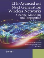
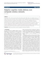
The receiving system also must despread the signal utilizing the exact
same PN code sent through an XOR gate that the transmitter utilized in
order to properly decode the initial signal. If the PN generator utilized by
the receiver is different or is not in synchronization with the transmitter’s
PN generator, then the information being transmitted will never be prop-
erly received and will be unintelligible. Figure 1-1 represents a series of
data that is encoded, transmitted, and then decoded back to the original
data stream for the receiver to utilize.
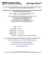
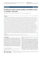
The chip rate also has a direct effect on the spreading of the CDMA sig-
nal. Figure 1-2 shows a brief summary of the effects on spreading the orig-
inal signal that the chosen chip rate has on the original signal. The heart of
CDMA lies in the point that the spreading of the initial information dis-
tributes the initial energy over a wide bandwidth. At the receiver, the sig-
nal is despread through reversing the initial spreading process where the
original signal is reconstructed for utilization. When the CDMA signal
experiences interference in the band, the despreading process despreads
the initial signal for use but at the same time spreads the interference so it
minimizes its negative impact on the received information.
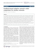
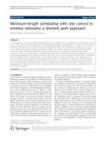
The number of PN chips per data bit is referred to as the processing gain
and is best represented by the following equation. Another way of referenc-
ing processing gain is the amount of jamming, or interference, power that is
reduced going through the despreading process. Processor gain is the
improvement in the signal-to-noise ratio of a spread spectrum system and
is depicted in Figure 1-3.
7
Wireless Communications
Wireless Communications
Downloaded from Digital Engineering Library @ McGraw-Hill (www.digitalengineeringlibrary.com)
Copyright © 2004 The McGraw-Hill Companies. All rights reserved.
Any use is subject to the Terms of Use as given at the website.
1.2.3 The Path to Third-Generation
Technology
In many ways, second-generation systems have come about because of fun-
damental weaknesses in first-generation technologies. First-generation
technologies have limited system capacity, they have very little protection
against fraud, they are subject to easy eavesdropping, and they have little
to offer in terms of advanced features. Second-generation systems are
designed to address all of these issues, and they have done a very success-
ful job.
Systems like IS-95, GSM, and IS-136 are much more secure; they also
offer higher capacity and more calling features. They are, however, still opti-
mized for voice service and they are not well suited to data communications.
Chapter 1
8
Figure 1-1
CDMA PN coding.
Wireless Communications
Downloaded from Digital Engineering Library @ McGraw-Hill (www.digitalengineeringlibrary.com)
Copyright © 2004 The McGraw-Hill Companies. All rights reserved.
Any use is subject to the Terms of Use as given at the website.
In the current environment of the Internet, electronic commerce, and mul-
timedia communications, limited support for data communications is a seri-
ous drawback. Although subscribers want to talk as much as ever, they now
want to communicate in a myriad of new ways, such as e-mail, instant mes-
saging, the World Wide Web, and so on. Not only do subscribers want these
services, they want mobility too. To provide all of these capabilities means
that new advanced technology is required
—
third-generation technology.
9
Wireless Communications
Figure 1-2
Summary of spread
spectrum. (a) Using
PN sequence and
transmitter with chip
(PN) duration of T/L.
(b) using correlation
and a synchronized
replica of the pn
sequence at the
receiver. (c) When
interface is present.
L/T
ϭ chip duration;
f
j
ϭ jamming
frequency; Bj ϭ
jammer’s bandwidth.
Wireless Communications
Downloaded from Digital Engineering Library @ McGraw-Hill (www.digitalengineeringlibrary.com)
Copyright © 2004 The McGraw-Hill Companies. All rights reserved.
Any use is subject to the Terms of Use as given at the website.
The need for third-generation mobile communications technology was
recognized on many different fronts, and various organizations began to the
address the issue as far back as the 1980s. The International Telecommu-
nications Union (ITU) was heavily involved and the work within the ITU
was originally known as Future Public Land Mobile Telecommunications
Systems (FPLMTS). Given the fact, however, that this acronym is difficult
to pronounce, it was subsequently renamed International Mobile Telecom-
munications
—
2000 (IMT-2000).
The IMT-2000 effort within the ITU has led to a number of recommen-
dations. These recommendations address areas such as user bandwidth
(144 Kbps for mobile service, and up to 2 Mbps for fixed service), richness
of service offerings (multimedia services), and flexibility (networks that
can support small or large numbers of subscribers). The recommendations
also specify that IMT-2000 should operate in the 2-GHz band. In general,
however, the ITU recommendations are mainly a set of requirements and
do not specify the detailed technical solutions to meet the requirements.
To address the technical solutions, the ITU has solicited technical propos-
als from interested organizations, and then selected/approved some of
those proposals. In 1998, numerous air interface technical proposals were
submitted. These were reviewed by the ITU, which in 1999 selected five
technologies for terrestrial service (non-satellite based). The five tech-
nologies are
Chapter 1
10
Figure 1-3
Processor gain:
B
D
ϭ bandwidth of
initial signal
B
S
ϭ bandwidth of
initial signal
spread
Gp ϭ
B
S
B
D
Wireless Communications
Downloaded from Digital Engineering Library @ McGraw-Hill (www.digitalengineeringlibrary.com)
Copyright © 2004 The McGraw-Hill Companies. All rights reserved.
Any use is subject to the Terms of Use as given at the website.
■ Wideband CDMA (WCDMA)
■ CDMA 2000 (an evolution of IS-95 CDMA)
■ TD-SCDMA (time division-synchronous CDMA)
■ UWC-136 (an evolution of IS-136)
■ DECT
These technologies represent the foundation for a suite of advanced
mobile multimedia communications services and are starting to be
deployed across the globe. Of these technologies, this book deals with four
—
WCDMA, CDMA2000, TD-SCDMA, and UWC-136.
1.3 Mobile Communications
Fundamentals
Even though the term “cellular” is often used in North America to denote
analog AMPS systems, most, though not all, mobile communications sys-
tems are cellular in nature. Cellular simply means that the network is
divided into a number of cells, or geographical coverage areas, as shown in
Figure 1-4. Within each cell is a base station, which contains the radio
transmission and reception equipment. It is the base station that provides
the radio communication for those mobile phones that happen to be within
the cell. The coverage area of a given cell is dependent upon a number of
factors such as the transmit power of the base station, the transmit power
of mobile, the height of the base station antennas, and the topology of the
landscape. The coverage of a cell can range from as little as about 100 yards
to tens of miles.
Specific radio frequencies are allocated within each cell in a manner that
depends on the technology in question. In most systems, a number of indi-
vidual frequencies are allocated to a given cell and those same frequencies
are reused in other cells that are sufficiently far away to avoid interference.
With CDMA, however, the same frequency can be reused in every cell.
Although the scheme shown in Figure 1-4 is certainly feasible and is some-
times implemented, it is common to sectorize the cells, as shown in Fig-
ure 1-5. In this approach, the base station equipment for a number of cells
is co-located at the edge of those cells, and directional antennas are used to
provide coverage over the area of each cell (as opposed to omnidirectional
antennas in the case where the base station is located at the center of a
11
Wireless Communications
Wireless Communications
Downloaded from Digital Engineering Library @ McGraw-Hill (www.digitalengineeringlibrary.com)
Copyright © 2004 The McGraw-Hill Companies. All rights reserved.
Any use is subject to the Terms of Use as given at the website.
cell). Sectorized arrangements with up to six sectors are known, but the
most common configuration is three sectors per base station in urban areas,
with two sectors per base station along highways.
Of course, it is necessary that the base stations be connected to a switch-
ing network and for that network to be connected to other networks, such
as the Public Switched Telephone Network (PSTN) in order for calls to be
made to and from mobile subscribers. Furthermore, it is necessary for infor-
mation about the mobile subscribers to be stored in a particular place on
the network. Given that different subscribers may have different services
and features, the network must know which services and features apply to
each subscriber in order to handle calls appropriately. For example, a given
subscriber may be prohibited from making international calls. Should the
subscriber attempt to make an international call, the network must disal-
low that call based upon the subscriber’s service profile.
Chapter 1
12
Figure 1-4
Cellular System.
Wireless Communications
Downloaded from Digital Engineering Library @ McGraw-Hill (www.digitalengineeringlibrary.com)
Copyright © 2004 The McGraw-Hill Companies. All rights reserved.
Any use is subject to the Terms of Use as given at the website.
13
Wireless Communications
Three-sector configuration
Two-sector configuration
Figure 1-5
Typical Sectorized
Cell Sites
(a) Three-sector
configuration
(b) Two-sector
configuration
Wireless Communications
Downloaded from Digital Engineering Library @ McGraw-Hill (www.digitalengineeringlibrary.com)
Copyright © 2004 The McGraw-Hill Companies. All rights reserved.
Any use is subject to the Terms of Use as given at the website.
1.3.1 Basic Network Architecture
Figure 1-6 shows a typical (although very basic) mobile communications
network. A number of base stations are connected to a Base Station Con-
troller (BSC). The BSC contains logic to control each of the base stations.
Among other tasks, the BSC manages the handoff of calls from one base
station to another as subscribers move from cell to cell. Note that in certain
implementations, the BSC may be physically and logically combined with
the MSC.
Connected to the BSC is the Mobile Switching Center (MSC). The MSC,
also known in some circles as the Mobile Telephone Switching Office
(MTSO), is the switch that manages the setup and teardown of calls to and
Chapter 1
14
Base Station
Controller
(BSC)
Mobile Switching
Center
(MSC)
Home
Location
Register
(HLR)
Base Station
Controller
(BSC)
other
networks
Figure 1-6
Basic Network
Architecture.
Wireless Communications
Downloaded from Digital Engineering Library @ McGraw-Hill (www.digitalengineeringlibrary.com)
Copyright © 2004 The McGraw-Hill Companies. All rights reserved.
Any use is subject to the Terms of Use as given at the website.
from mobile subscribers. The MSC contains many of the features and func-
tions found in a standard PSTN switch. It also contains, however, a number
of functions that are specific to mobile communications. For example, the
BSC functionality may be contained with the MSC in certain systems, par-
ticularly in first-generation systems. Even if the BSC functionality is not
contained within the MSC, the MSC must still interact with a number of
BSCs over an interface that is not found in other types of networks. Fur-
thermore, the MSC must contain a logic of its own to deal with the fact that
the subscribers are mobile. Part of this logic involves an interface to one or
more HLRs, where subscriber-specific data is held.
The HLR contains subscription information related to a number of sub-
scribers. It is effectively a subscriber database and is usually depicted in
diagrams as a database. The HLR does, however, do more that just hold
subscriber data; it also plays a critical role in mobility management
—
that
is, the tracking of a subscriber as he or she moves around the network. In
particular, as a subscriber moves from one MSC to another, each MSC in
turn notifies the HLR. When a call is received from the PSTN, the MSC that
receives the call queries the HLR for the latest information regarding the
subscriber’s location so that the call can be correctly routed to the sub-
scriber. Note that, in some implementations, HLR functionality is incorpo-
rated within the MSC, which leads to the concept of a “home MSC” for a
given subscriber.
The network depicted in Figure 1-6 can be considered to represent the
bare minimum needed to provide a mobile telephony service. These days, a
range of different features’ services are offered in addition to just the capa-
bility to make and receive calls. Therefore, most of today’s mobile commu-
nications networks are much more sophisticated than the network depicted
in Figure 1-6. As we progress through this book, we will introduce many
other network elements and interfaces as we build from the fundamentals
to the sophisticated technologies of third-generation networks.
1.3.2 Air Interface Access Techniques
Radio spectrum is a precious and finite resource. Unlike other transmission
media such as copper or fiber facilities, it is not possible to simply add radio
spectrum when needed. Only a certain amount of spectrum is available and
it is critical that it be used efficiently, and be reused as much as possible.
Such requirements are at the heart of the radio access techniques used in
mobile communications.
15
Wireless Communications
Wireless Communications
Downloaded from Digital Engineering Library @ McGraw-Hill (www.digitalengineeringlibrary.com)
Copyright © 2004 The McGraw-Hill Companies. All rights reserved.
Any use is subject to the Terms of Use as given at the website.
1.3.2.1 Frequency Division Multiple Access (FDMA) Of the common
multiple access techniques used in mobile communications systems, FDMA
is the simplest. With FDMA, the available spectrum is divided into a num-
ber of radio channels of a specified bandwidth, and a selection of these chan-
nels is used within a given cell. In analog AMPS, for example, the available
spectrum is divided into blocks of 30 kHz. A number of 30-kHz channels
are allocated to each cell, depending on the expected traffic load for the cell.
When a subscriber wants to place a call, one of the 30-kHz channels is allo-
cated exclusively to the subscriber for that call.
In most FDMA systems, separate channels are used in each direction
—
from network to subscriber (downlink) and from subscriber to network
(uplink). For example, in analog AMPS, when we talk about 30-kHz chan-
nels, we are actually talking about two 30-kHz channels, one in each direc-
tion. Such an approach is known as Frequency Division Duplex (FDD) and
normally a fixed separation exists between the frequency used in the uplink
and that used in the downlink. This fixed separation is known as the duplex
distance. For example, in many systems in North America, the duplex dis-
tance is 45 MHz. Thus, in such a system, channel 1 corresponds to two chan-
nels (uplink and downlink) with a separation of 45 MHz between them. An
FDD FDMA technique can be represented as shown in Figure 1-7.
FDD is not the only duplexing scheme, however. Another technique
known as Time Division Duplex is also used. In such a system, only one
channel is used for both uplink and downlink transmissions. With TDD, the
channel is used very briefly for uplink, then very briefly for downlink, then
very briefly again for uplink, and so on. TDD is not very common in North
America, but it is widely used in systems deployed in Asia.
1.3.2.2 Time Division Multiple Access (TDMA) With Time Division
Multiple Access (TDMA), radio channels are divided into a number of time
slots, with each user assigned a given timeslot. For example, on a given
radio frequency, user A might be assigned timeslot number 1 and user B
might be assigned time slot number 3. The allocation is performed by the
network as part of the call establishment procedure. Thus, the user’s device
knows exactly which timeslot to use for the remainder of the call, and the
device times its transmissions exactly to correspond with the allocated time
slot. This technique is depicted in Figure 1-8.
Typically, a TDMA system is also an FDD system, as shown in Figure 1-8,
although TDD is used in some implementations. Furthermore, TDMA sys-
tems normally also use FDMA. Thus, the available bandwidth is divided
into a number of smaller channels as in FDMA and it is these channels that
Chapter 1
16
Wireless Communications
Downloaded from Digital Engineering Library @ McGraw-Hill (www.digitalengineeringlibrary.com)
Copyright © 2004 The McGraw-Hill Companies. All rights reserved.
Any use is subject to the Terms of Use as given at the website.
17
Wireless Communications
Time
F
r
e
q
u
e
n
c
y
Channel 1
Channel 2
Channel 3
Channel 1
Channel 2
Channel 3
.
.
.
.
.
.
.
.
.
.
.
.
Duplex
Distanc
e
Figure 1-7
FDMA.
Time
F
r
e
q
u
e
n
c
y
.
.
.
.
.
.
.
.
.
.
.
.
Duplex
Distance
User 1 User 2 User 3
User 5 User 6User 4
User 1 User 2 User 3
User 5 User 6User 4
.
.
.
.
.
.
.
.
.
.
.
.
.
.
.
.
.
.
.
.
.
.
.
.
radio channel 1
radio channel 2
radio channel 1
radio channel 2
Figure 1-8
TDMA.
Wireless Communications
Downloaded from Digital Engineering Library @ McGraw-Hill (www.digitalengineeringlibrary.com)
Copyright © 2004 The McGraw-Hill Companies. All rights reserved.
Any use is subject to the Terms of Use as given at the website.
are divided into timeslots.The difference between a pure FDMA system and
a TDMA system that also uses FDMA is that, with the TDMA system, a
given user does not have exclusive access to the radio channel.
Implementing a TDMA system can be done in many ways. For example,
different TDMA systems may have different numbers of time slots per radio
channel and/or different time slot durations, and/or different radio channel
bandwidths. Although, in the United States, the term TDMA is often used
to refer to IS-136, such a usage of the term is incorrect because IS-136 is
just one example of a TDMA system. In fact, GSM is also a TDMA system.
1.3.2.3 Code Division Multiple Access (CDMA) With CDMA, neither
the time domain nor the frequency domain are subdivided. Rather, all users
share the same radio frequency at the same time. This approach obviously
means that all users interfere with each other. Such interference would be
intolerable if the radio frequency bandwidth were limited to just the band-
width that would be needed to support a single user. To overcome this dif-
ficulty, CDMA systems use a technique called spread spectrum, which
involves spreading the signal over a wide bandwidth. Each user is allocated
a code or sequence and the bit rate of the sequence is much greater than
the bit rate of the information being transmitted by the user. The informa-
tion signal from the user is modulated with the sequence assigned to the
user and, at the far end, the receiver looks for the sequence in question.
Having isolated the sequence from all of the other signals (which appear
as noise), the original user’s signal can be extracted.
TDMA systems have a very well-defined capacity limit. A set number
of channels and a set number of time slots exist per channel. Once all
time slots are occupied, the system has reached capacity. CDMA is some-
what different. With CDMA, the capacity is limited by the amount of
noise in the system. As each additional user is added, the total interfer-
ence increases and it becomes harder and harder to extract a given user’s
unique sequence from the sequences of all the other users. Eventually,
the noise floor reaches a level where the inclusion of additional users
would significantly impede the system’s capability to filter out the trans-
mission of each user. At this point, the system has reached capacity.
Although it is possible to mathematically model this capacity limit, exact
modeling can prove a little difficult, since the noise in the system
depends on factors such as the transmission power of each individual
mobile, thermal noise, and the use of discontinuous transmission (only
transmitting when something is being said). By making certain reason-
able assumptions in the design phase, however, it is possible to design a
Chapter 1
18
Wireless Communications
Downloaded from Digital Engineering Library @ McGraw-Hill (www.digitalengineeringlibrary.com)
Copyright © 2004 The McGraw-Hill Companies. All rights reserved.
Any use is subject to the Terms of Use as given at the website.
CDMA system that provides relatively high capacity without significant
quality degradation.
IS-95/J-STD-008 is the only widely deployed CDMA system for mobile
communications.This system uses a channel bandwidth of 1.23 MHz and is
an FDD system. The fact that the bandwidth is 1.23 MHz means that the
total system bandwidth (typically, 10 MHz, 20 MHz, or 30 MHz) can accom-
modate several CDMA radio frequency (RF) channels. Therefore, like
TDMA, IS-95 CDMA also uses FDMA to some degree. In other words,
within a given cell, more than one RF channel may be available to system
users.
A significant advantage of CDMA is the fact that it practically eliminates
frequency planning. Other systems are very sensitive to interference, mean-
ing that a given frequency can be reused only in another cell that is
sufficiently far away to avoid interference. In a commercial mobile commu-
nications network, cells are constantly being added, or capacity is being
added to existing cells, and each such change must be done without causing
undue interference. If interference is likely to be introduced, then retuning
of part of the network is required. Such retuning is needed frequently and
can be an expensive effort. CDMA, however, is designed to deal with inter-
ference and, in fact, it allows a given RF carrier to be reused in every cell.
Therefore, there is no need to worry about retuning the network when a
new cell is added.
1.3.3 Roaming
The discussion so far has focused largely on the methods used to access the
network over the air interface. The air interface access is, of course,
extremely important. Other aspects, however, are necessary in order to make
a wireless communications network a mobile communications network.
Mobility implies that subscribers be able to move freely around the net-
work and from one network to another. This requires that the network
tracks the location of a subscriber to a certain accuracy so that calls des-
tined for the subscriber may be delivered. Furthermore, a subscriber should
be able to do so while engaged in a call.
The basic approach is as follows. First, when a subscriber initially
switches on his or her mobile phone, the device itself sends a registration
message to the local MSC. This message includes a unique identification for
the subscriber. Based on this identification, the MSC is able to identify the
HLR to which the subscriber belongs, and the MSC sends a registration
19
Wireless Communications
Wireless Communications
Downloaded from Digital Engineering Library @ McGraw-Hill (www.digitalengineeringlibrary.com)
Copyright © 2004 The McGraw-Hill Companies. All rights reserved.
Any use is subject to the Terms of Use as given at the website.
message to the HLR to inform the HLR of the MSC that now serves the
subscriber. The HLR then sends a registration cancellation message to the
MSC that previously served the subscriber (if any) and then sends a con-
firmation to the new serving MSC.
When mobile communications networks were initially introduced, only
the air interface specification was standardized. The exact protocol used
between the visited MSC and the HLR (or home MSC) was vendor-specific.
The immediate drawback was that the home system and visited system had
to be from the same vendor if roaming was to be supported. Therefore, a
given network operator needed to have a complete network from only one
vendor. Moreover, roaming between networks worked only if the two net-
works used equipment from the same vendor. These limitations severely
curtailed roaming.
This problem was addressed in different ways on either side of the
Atlantic. In North America, the problem was recognized fairly early, and an
effort was undertaken to establish a standard protocol between home and
visited systems. The result of that effort was a standard known as IS-41.
This standard has been enhanced significantly over the years and the cur-
rent revision of the standard is revision D. IS-41 is used for roaming in
AMPS systems, IS-136 systems, and IS-95 systems.
Meanwhile, in Europe, nothing was done to address the roaming issue
for first-generation systems, but a major effort was applied to ensuring that
the problem was addressed in second-generation technology
—
specifically
GSM. Consequently, when GSM specifications were created, they addressed
far more than just the air interface. In fact, most aspects of the network
were specified in great detail, including the signaling interface between
home and visited systems. The protocol specified for GSM is known as the
GSM Mobile Application Part (MAP). Like IS-41, GSM MAP has also been
enhanced over the years.
Strictly speaking, the term MAP is not specific to GSM. In fact, the term
refers to any mobility-specific protocol that operates at layer 7 of the Open
Systems Interconnection (OSI) seven-layer stack. Given that IS-41 also
operates layer 7, the term MAP is also applicable to IS-41.
1.3.4 Handoff/Handover
Handoff (also known as handover) is the ability of a subscriber to maintain
a call while moving within the network. The term handoff is typically used
Chapter 1
20
Wireless Communications
Downloaded from Digital Engineering Library @ McGraw-Hill (www.digitalengineeringlibrary.com)
Copyright © 2004 The McGraw-Hill Companies. All rights reserved.
Any use is subject to the Terms of Use as given at the website.
with AMPS, IS-136, and IS-95, while handover is used in GSM. The two
terms are synonymous.
Handoff usually means that a subscriber travels from one cell to another
while engaged in a call, and that call is maintained during the transition
(ideally without the subscriber noticing any change). In general, handoff
means that the subscriber is transitioned from one radio channel (and/or
timeslot) to another. Depending on the two cells in question, the handoff can
be between two sectors on the same base station, between two BSCs,
between two MSCs belonging to the same operator, or even between two
networks. (Note that inter-network handoff is not supported in some sys-
tems, often mainly for billing reasons.)
It is also possible to handoff a call between two channels in the same cell.
This could occur when a given channel in a cell is experiencing interference
that is affecting the communication quality. In such a case, the subscriber
would be moved to another frequency that is subject to less interference. A
handoff scenario is depicted in Figure 1-9.
How does the system determine that a handoff needs to occur? Basically,
two main approaches are used. In first-generation technologies, a handoff is
21
Wireless Communications
Cellular Base Station
A
Cellular Base Station
B
Cellular Base Station
A
Cellular Base Station
B
Serving Cell B
Serving Cell A
Figure 1-9
Handover.
(a) Pre-handoff
(b) Post-handoff
Wireless Communications
Downloaded from Digital Engineering Library @ McGraw-Hill (www.digitalengineeringlibrary.com)
Copyright © 2004 The McGraw-Hill Companies. All rights reserved.
Any use is subject to the Terms of Use as given at the website.
generally controlled by the network. The network measures the signal
strength from a mobile as received at the serving cell. If it begins to fall
below a certain threshold, then nearby cells are requested to perform signal
strength measurements. If a nearby cell records a better signal strength,
then it is highly likely that the subscriber has moved to the coverage of that
cell. The new cell is instructed by the BSC or MSC (typically just the MSC,
since first-generation systems do not have BSCs) to allocate a channel for
the subscriber. Once that allocation is performed, the network instructs the
mobile to swap to the new channel. This is known as a network-controlled
handoff, because the network determines when and how a handoff is to
occur.
In more recent technologies, a technique known as mobile assisted han-
dover (MAHO) is the most common. In the approach, the network provides
the mobile with a list of base station frequencies (those of nearby base sta-
tions). The mobile makes periodic measurements of the signals received
from those base stations (as well as the serving base station), including sig-
nal strength and signal quality (usually determined from bit error rates),
and it sends the corresponding measurement reports to the network. The
network analyzes the reports and makes a determination of if and how a
handoff should occur. Assuming that a handoff is required, then the net-
work reserves a channel on the new cell and sends an instruction to the
mobile to move to that channel, which it does.
1.4 Wireless Migration
In the previous sections of this chapter, some of the various technology plat-
forms were discussed. The existing wireless operators today, regardless of
the frequency band or existing technology deployed have or are making
very fundamental decisions as to which direction in the 3G evolution they
will take. The decision on 3G technology will define a company’s position in
the marketplace for years to come.
Some existing operators and new entrants are letting the technology
platform be defined by the local regulator, thereby eliminating the platform
decision. However, the majority of the operators need to determine which
platform they must utilize. Since the platforms to pick from utilize different
Chapter 1
22
Wireless Communications
Downloaded from Digital Engineering Library @ McGraw-Hill (www.digitalengineeringlibrary.com)
Copyright © 2004 The McGraw-Hill Companies. All rights reserved.
Any use is subject to the Terms of Use as given at the website.
access technologies, they are by default not directly compatible. The uti-
lization of different access technologies for the realization of 3G also intro-
duces several interesting issues related to the migration from 2G to 3G. The
migration path from 2G to 3G is referred to as 2.5G and involves an interim
position for data services that are more advanced than 2G, but not as robust
as the 3G envisioned data services.
Some of the migration strategies for an existing operator involve
■ Overlay
■ Spectrum segmentation
The overlay approach typically involves implementing the 2.5 technology
over the existing 2G system and then implementing 3G as either an over-
lay or in a separate part of the radio frequency spectrum they are allocated,
spectrum segmentation.
The choice of whether to use an overlay or spectrum segmentation is nat-
urally dependant upon the technology platform that is currently being
used, 2G, the spectrum available, the existing capacity constraints, and
marketing. Marketing is involved with the decision because of the impact to
the existing subscriber base and services that are envisioned to be offered.
Some of the decisions are rather straightforward involving upgrading
portions of the existing technology platforms that are currently deployed.
Other operators have to make a decision as to which technology to utilize
since they either are building a new system or have not migrated to a 2G
platform, using only 1G.
In later chapters various migration strategies are discussed relative to
the underlying technology platform that exists.
1.5 Harmonization Process
Harmonization refers to the vision and objective of the IMT2000 specifica-
tion that enables the various technology platforms that are defined in that
specification to interact with each other. True harmonization relative to the
capability of a CDMA2000 and WCDMA system is based on having sub-
scriber units that operate in both technologies. The access infrastructure
being able to support both is a goal, but not one that is in the near future.
23
Wireless Communications
Wireless Communications
Downloaded from Digital Engineering Library @ McGraw-Hill (www.digitalengineeringlibrary.com)
Copyright © 2004 The McGraw-Hill Companies. All rights reserved.
Any use is subject to the Terms of Use as given at the website.
1.6 Overview of Following Chapters
This chapter has served as a brief introduction to mobile communications
systems. The brief overview that has been given, however, is certainly not a
sufficient background to enable a good understanding of third-generation
technology. Therefore, before tackling the details of third-generation sys-
tems, it is necessary to better describe first- and second-generation systems.
Chapter 2, “First Generation (1G),” addresses first-generation technology
and Chapter 3, “Second Generation (2G),” delves into the second-generation
systems. The remaining chapters focus on third-generation systems and
some of the migration paths to obtainment of the IMT2000 vision.
References
AT&T. "Engineering and Operations in the Bell System," 2nd Ed., AT&T
Bell Laboratories, Murry Hill, N.J., 1983.
Barron, Tim. "Wireless Links for PCS and Cellular Networks," Cellular
Integration, Sept. 1995, pgs. 20–23.
Brewster. "Telecommunications Technology," John Wiley & Sons, New York,
NY, 1986.
Brodsky, Ira. "3G Business Model," Wireless Review, June 15, 1999, pg. 42.
Daniels, Guy. "A Brief History of 3G," Mobile Communications Interna-
tional, Issue 65, Oct. 99, pg. 106.
Gull, Dennis. "Spread-Spectrum Fool’s Gold?" Wireless Review, Jan. 1, 1999
pg. 37.
Homa, Harri, and Antti Toskala. "WCDMA for UMTS," John Wiley & Sons,
2000.
Smith, Clint. "Practical Cellular and PCS Design," McGraw-Hill, 1997.
Smith, Gervelis. "Cellular System Design and Optimization," McGraw-Hill,
1996.
Chapter 1
24
Wireless Communications
Downloaded from Digital Engineering Library @ McGraw-Hill (www.digitalengineeringlibrary.com)
Copyright © 2004 The McGraw-Hill Companies. All rights reserved.
Any use is subject to the Terms of Use as given at the website.