Astm a 627 03 (2011)
Bạn đang xem bản rút gọn của tài liệu. Xem và tải ngay bản đầy đủ của tài liệu tại đây (688.22 KB, 11 trang )
Designation: A627 − 03 (Reapproved 2011)
Standard Test Methods for
Tool-Resisting Steel Bars, Flats, and Shapes for Detention
and Correctional Facilities1
This standard is issued under the fixed designation A627; the number immediately following the designation indicates the year of
original adoption or, in the case of revision, the year of last revision. A number in parentheses indicates the year of last reapproval. A
superscript epsilon (´) indicates an editorial change since the last revision or reapproval.
This standard has been approved for use by agencies of the U.S. Department of Defense.
1. Scope
2. Referenced Documents
2.1 ASTM Standards:2
A629 Specification for Tool-Resisting Steel Flat Bars and
Shapes for Security Applications (Withdrawn 2004)3
C39/C39M Test Method for Compressive Strength of Cylindrical Concrete Specimens
E4 Practices for Force Verification of Testing Machines
E18 Test Methods for Rockwell Hardness of Metallic Materials
E329 Specification for Agencies Engaged in Construction
Inspection, Testing, or Special Inspection
1.1 These test methods cover requirements for simulated
service tests and testing equipment for determining the performance characteristics of various types and shapes of steels
designated for use in detention and correctional facilities as
fixed barriers to prevent egress and to control passage.
1.2 It is the intent of these test methods to help ensure that
opening assemblies such as detention security windows,
grilles, bar grating, and other physical barriers incorporating
steel bars perform at or above minimum acceptable levels for
control of passage to unauthorized or secure areas, for confinement of inmates and to delay or frustrate escape attempts. To
meet the intent of these test methods, opening assembles must
perform to grade requirements shown in Tables X1.1 and X1.2
in Appendix X1.
3. Terminology
3.1 Definitions:
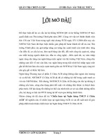
3.1.1 bars, n—round, ribbed, hexagonal, or other shaped
bars that can be readily reduced to a round cross-sectional
shape, 7⁄8-in. (22.2-mm) or 1-in. (25.4-mm) diameter (see Fig.
1). Also flat bars: 1⁄4 by 2 in. (6.4 by 50.8 mm); 5⁄16 by 21⁄4 in.
(7.9 by 57.2 mm) or 3⁄8 by 21⁄2 in. (9.6 by 63.5 mm).
3.1.2 composite tool-resisting steel bar/flat, n—a bar/flat
that is a composite of a tungsten carbide or other hard material,
for cutting resistance and of a high strength, low alloy steel,
heat treated up to HRC 45 max. hardness for impact and
deflection resistance.
3.1.3 cutting test, n—a simulated service test in which the
rating is based on the number of a specific type of tungsten
carbide rod saws required to cut through the bar.
3.1.4 effective tool-resisting (ETR) area, n—the crosssectional area of the portion of the bar that is tool resistant.
3.1.5 equipment manufacturer, n—a manufacturer who fabricates and assembles security products, including toolresisting steel bars, for installation in areas requiring security
against ingress and egress. This manufacturer processes the
1.3 These test methods apply primarily to the steels used as
essential components of detention security windows, grilles,
bar grating, and so forth, in opening assemblies enclosing or
separating secure areas of detention/correctional facilities.
1.4 The values stated in inch-pound units are to be regarded
as standard. The SI values given in parentheses are for
information only.
1.5 This standard updates and combines two previous
standards, ASTM Specifications A627-95 and A629-94, establishing new security grades and time durations.
1.6 This standard does not purport to address all of the
safety concerns, if any, associated with its use. It is the
responsibility of the user of this standard to establish appropriate safety and health practices and determine the applicability of regulatory limitations prior to use.
1
This specification is under the jurisdiction of ASTM Committee F33 on
Detention and Correctional Facilities and is the direct responsibility of Subcommittee F33.02 on Physical Barriers.
Current edition approved July 1, 2011. Published September 2011. Originally
approved in 1968. Last previous edition approved in 2003 as A627 – 03. DOI:
10.1520/A0627-03R11.
2
For referenced ASTM standards, visit the ASTM website, www.astm.org, or
contact ASTM Customer Service at For Annual Book of ASTM
Standards volume information, refer to the standard’s Document Summary page on
the ASTM website.
3
The last approved version of this historical standard is referenced on
www.astm.org.
Copyright © ASTM International, 100 Barr Harbor Drive, PO Box C700, West Conshohocken, PA 19428-2959. United States
1
A627 − 03 (2011)
FIG. 1 Shaped Bars
4. Significance and Use
semi-finished bar and fabricates finished products suitable for
use in opening assemblies requiring these specified performance characteristics. This manufacturer is also responsible
for heat treating, fabricating, and assembling all ancillary items
so as not to impair the performance characteristics of the
bar/flat.
3.1.6 hardness, n—indicated as HRC, refers to hardness
measured according to Test Methods E18 on the Rockwell C
scale.
3.1.7 homogeneous tool-resisting bar/flat, n—a bar/flat that
is nominally of uniform chemistry throughout, usually high
strength, low alloy steel heat treated to HRC 61 min.—HRC 64
max. hardness to a case depth of 0.150 in. min. for rounds and
each longitudinal edge hardened to 0.250-in. min. for flats.
3.1.8 lot, n—all bars/flats of the same nominal crosssectional dimensions from the same mill heat and production
lot.
3.1.9 performance characteristic, n—the response to any
one test (drop-weight, cutting, or deflection) shown in Tables
X1.1 and X1.2.
3.1.10 test completion, n—conduct one test sequence for
each lot of bars.
3.1.11 testing laboratory, n—approved third party testing
laboratory, accredited to I.S.O. Standard 17025-99, selected by
the equipment manufacturer.
3.1.12 test sequence:
3.1.12.1 round bars, n—conduct drop-weight test and cutting test on one specimen bar and conduct deflection test on
one additional specimen bar.
3.1.12.2 flat bar, n—conduct cutting test followed by hardness tests on the same flat bar.
4.1 Security barriers used in detention/correctional facilities
are a major concern for their administrative officials. These test
methods are designed to identify levels of physical security for
openings such as fixed and operable exterior and interior
windows, bar gratings, grilles for mechanical ducts, and so
forth in walls that enclose or separate secure areas.
4.2 These test methods are intended to evaluate the resistance of these barriers to violent attacks using battering devices
such as benches, bunks or tables, and so forth to bend or break
the steel bars and to surreptitious attacks by cutting/abrading
the steel bars over prolonged periods of time using handheld
grit-type cutting/abrading media such as tungsten carbide rod
saws. External attacks and attacks by corrosive agents and
other means not typically available to inmates are not addressed in this standard.
4.3 The primary purpose or result of these test methods is to
approximate the levels of abuse to which these physical
security barriers will potentially be subjected in the
correctional/detention facility. The desired result of its use is to
help provide a degree of assurance of protection to the public,
facility personnel, and inmates.
4.4 It is recommended that detention/correctional facility
administrators provide for adequate training, supervision, regular inspection, and preventive maintenance programs to enable
the barriers to function as intended throughout their expected
service life.
5. Ordering Information
5.1 Orders for material under this specification shall include
the following information:
2
A627 − 03 (2011)
6.1.2.6 All specimen bars used in all test sequences shall be
permanently marked for complete identification and held by
the equipment manufacturer for no less than three years after
the tests are completed.
6.1.3 Procedure:
6.1.3.1 Conduct the test on one specimen bar selected as
required in 6.1.2.1 – 6.1.2.4 inclusive; stop after 50 consecutive
blows, or sooner if the bar fails.
6.1.3.2 Drop the tup repeatedly so as to deliver 50 consecutive blows at the same point on the specimen bar. It shall be
properly weighted and guided so as to produce the required
impact in foot-pounds for each blow.
6.1.3.3 Apply each blow at the same point and on the same
side of the specimen bar, perpendicular to the 14-in. (356-mm)
axis and at the midpoint (60.250 in. (66.4 mm)) between the
supports of the specimen bar.
6.1.3.4 To prevent an unmeasured secondary impact after
each drop from the test height, make provisions in the testing
procedure to prevent the weighted tup from rebounding and
again striking the test specimen.
6.1.3.5 The drop-weight machine is of simple design constructed from readily available rolled and shaped structural
steel products. Raise the weight by any mechanical or electrical
hoisting equipment or, alternatively, by hand. Provide a mechanical or electrical mechanism to achieve quick release of
the weight. This testing machine shall conform to the requirements of Sections 16 and 18 of Practices E4 as modified by the
requirements of this specification or the manufacturer of the
testing machine, provided that modifications of this equipment
or assembly details provide a functionally acceptable dropweight machine.
6.1.3.6 For 7⁄8-in. (22.2-mm) diameter bar, the drop-weight
machine shall drop a weight of 50 lb. (22.7 kg) from a height
of 2 ft (611 mm). For 1-in. (25.4-mm) diameter bar, the
drop-weight machine shall drop a weight of 50 lb. (22.7 kg)
from a height of 3 ft (916 mm).
6.1.3.7 The hardened tup that strikes the specimen bar shall
be rounded initially to 0.250-in. (6.35-mm) radius and shall be
heat treated to a minimum hardness of HRC 50.
6.1.3.8 The entire tup and weight shall fall freely by gravity
when released and shall be inspected after each five blows to
determine that the original shape of the tup has not been
seriously deformed through repeated impact. If the 0.250-in.
radius is flattened to more than 0.312-in. radius, the test shall
be interrupted and the tup shall be restored to the 0.250-in.
radius before testing is continued.
6.1.3.9 The fixed anvil-type supports for the 14-in. specimen bar shall be located no less than 2 in. (51 mm) above the
bed of the testing machine and spaced 12 in. (305 mm) apart
61⁄16 in. (61.59 mm). They shall be so constructed as to hold
the same point of the specimen bar underneath the tup for each
drop of the weight by preventing significant rotation or lateral
movement of the specimen bar during the conduct of the 50
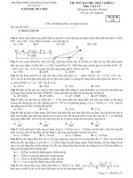
blows required for a test (see Fig. 2 for a typical example).
6.1.3.10 The part of the machine in which the specimen bar
is placed for drop-weight testing shall be surrounded by a metal
guard screen for protection, as the breaking into two halves of
5.1.1 Name of material (homogeneous tool-resisting steel or
composite tool resisting steel),
5.1.2 Dimensions (nominal diameter or cross section),
5.1.3 Cross section (double-ribbed, round, hexagon, square,
rectangular, flat, or other shapes),
5.1.4 ASTM designation,
5.1.5 Test reports (if required),
5.1.6 Certification (if required), and
5.1.7 Special requirements (if any).
5.2 It is possible that bars of different nominal diameters/
shapes are specified or shown on drawings. Each bar of the
nominal diameter/cross section shape tested shall meet or
exceed the minimum requirements of all tests for the diameter/
shape shown in Tables X1.1 and X1.2.
5.3 The minimum levels of performance per type of steel
required in Tables X1.1 and X1.2 for each bar are not
independent characteristics, but are interrelated to each other
and though any one performance characteristic shall be permitted to exceed the requirements, none of the other characteristics shall be permitted to exhibit a performance lower than
the minimum performance levels shown.
6. Mechanical Requirements
6.1 Drop-Weight Test:
6.1.1 Requirements—The specimen bar shall not crack,
visibly fracture, or take a permanent set of more than 0.25 in.
(6.4 mm) at the midspan between support points under the
impact of 50 consecutive blows of a force as specified in Table
X1.1 under “Drop-Weight Test.”
6.1.2 Number of Specimens:
6.1.2.1 The equipment manufacturer shall randomly select
three bars/flats no less than 4 ft (1.22 m) in length from the lot
for which the test is conducted. These 4-ft lengths shall be
permanently marked after production or heat treating for easy
identification of mill heat number, lot number, and individual
identification of the two specimen bars taken from each of the
4-ft lengths.
6.1.2.2 Two 14-in. (356-mm) specimen bars shall be cut
with a friction saw from each of the 4-ft lengths after heat
treating. Each 14-in. specimen bar shall be permanently
marked for easy identification as to production, mill heat
number, lot number, and identity of the longer bar from which
it was taken.
6.1.2.3 The testing laboratory shall, as its own choice, select
two specimen bars taken from the same 4-ft length of bar for
conduct of each test sequence.
6.1.2.4 It shall be the responsibility of the equipment
manufacturer to determine, by visual inspection, that no
unusual defects exist in the specimen bars and to determine that
the specimen bars represent usual conditions, representative of
all bars to be used from the lot.
6.1.2.5 In each test sequence, one specimen bar (prepared
and selected as described in 6.1.2.1 – 6.1.2.3, inclusive) shall
be used for both the drop-weight and cutting test. A second
specimen bar, prepared and selected in the same manner and
taken from the same 4-ft length of bar shall be used for the
deflection test in each test sequence.
3
A627 − 03 (2011)
FIG. 2 Typical Example of Drop-Weight Test Apparatus
the bar has the potential to cause them to be ejected laterally
from the machine with projectile-like velocities (see Fig. 2 for
a typical example).
6.1.3.11 The addition of other safety devices or features are
permitted provided that a functionally equivalent drop-weight
machine is maintained.
6.1.3.12 The entire test machine shall be securely bolted to
a rigid foundation, such as a concrete floor, so as to eliminate
any possible cushioning effect that would diminish the force of
the impact generated by the falling top.
6.1.3.13 In addition to initial markings required for preparation of specimens, all specimen bars shall be given a durable
marking, before beginning the drop-weight test, showing the
side of the bar and the point at which the top contacted the bar.
60
6.2.1.2 Interpretation of Cutting Test Results—
Homogeneous Tool-Resisting Bars/Flats—The cutting test
shall be performed with number of rod saws as required for
total severance.
6.2.1.3 Interpretation of Cutting Test Results--Composite
Tool-Resisting Bars/Flats—The cutting test shall be performed
with min. 60 rod saws.
6.2.2 Number of Specimens:
6.2.2.1 The same specimen bar that has acceptably passed
the drop-weight test shall be subjected to the cutting test to
determine its cutting-test performance characteristic.
6.2.2.2 It shall not be permissible to change, by heat treating
or any other method, any of the qualities for characteristics of
the specimen bar as tested under the requirements of the
drop-weight test before the specimen being subjected to the
cutting test.
6.2.2.3 Ribs on double-ribbed bars or points on hexagonal
bars or any other configuration shall be permitted to be used to
lock and counterlock bars in various security applications.
However, only the round circumference that fits within the
cross section of the shape shall be used to compute the
cross-sectional area of the bar being tested in the cutting test
(see Fig. 1).
6.2.3 Test Method:
6.2.3.1 The testing laboratory shall be responsible for determining that all rod saws used for testing comply with the
specifications for tungsten carbide rod saws, which are as
follows: 0.090-in. (2.1-mm) diameter, standard grit, 12-in.
(304-mm) approximate length.
6.2 Cutting Test:
6.2.1 Requirements—Performance characteristics shall be
such that the bar tested is not severed with the number of rod
saws required in Tables X1.1 and X1.2 under “Cutting Test.”
6.2.1.1 Interpretation of Cutting Test Results Based Upon
Effective Tool-Resisting (ETR) Area—Composite Steel—The
equation for computing the theoretical number of rod saws
required to cut through a composite T.R. bar/flat is:
E 5 ~ A T.R
⁄
a T.R. ! 3 60
= number of rod saws used in 18 000 cutting cycles
(300 cycles/rod saw).
(1)
where:
E
= calculated number of rod saws to sever the E.T.R.
area within the steel bars/shapes,
AT.R = tool-resisting area that fits within the steel bar/shape
cross-sectional area, in.2 ,
aT.R. = tool-resistant area of the segment cut in 18 000
cutting cycles, in.2, and
4
A627 − 03 (2011)
6.3.1 Requirements—The specimen shall not fracture or
take a permanent set of more than 1⁄4 in. (6.4 mm) at the
midspan between the 12-in. (305-mm) support points when a
specimen bar of nominal diameter shown in Table X1.1 is
subjected to a load as required under 6.3.3.
6.3.2 Number of Specimens—The other specimen bar (see
6.1.2.5) taken from the same 4-ft (1.22-m) length of bar as the
specimen used for the drop-weight and cutting tests shall be
used in conducting the deflection test.
6.3.3 Test Method:
6.3.3.1 The testing machine shall conform to the requirements of Test Method C39/C39M and shall be permitted to be
of any type that is of sufficient capacity to provide the rate of
loading required.
6.3.3.2 Fixed supports spaced 12 in. (305 mm) apart (61⁄16
in. (61.59 mm) supporting the specimen bar no less than 2 in.
(51 mm) above the bed plate of the testing machine shall be
provided beneath the pressure ram. The machine shall be so
constructed as to prevent the specimen bar from turning under
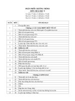
pressure, providing such construction shall not restrict deflection in any manner (see Fig. 4 for a typical example).
6.3.3.3 A tup, rounded to a 0.250-in. (6.35-mm) radius,
hardened to a HRC 50, minimum, shall be mounted on the ram
of the testing machine and used to transmit pressure from the
ram to the bar. The contact of the tup with the specimen bar
6.2.3.2 The test shall be conducted on a 6- by 6-in. (150- by
150-mm) gravity-feed, power-hacksaw machine under the
following conditions:
Rod saw tension
Static gravity feed pressure (ctr. of
stroke)
Dynamic feed pressure
Maximum lift on return strokes
Speed
Length of stroke
Cutting fluid
200 lbf (890 N)
26 ± 1 lbf (116 ± 4 N)
21-37 (93-165 N)
0 in. (0 mm)
60 strokes/min.
6 in. (152 mm)
none
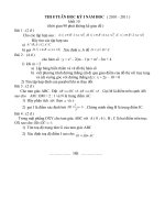
6.2.3.3 The cutting resistance of the specimen bar shall be
determined by placing it firmly in a vice underneath the rod
saw in the power hacksaw and causing 18 000 cutting cycles of
the rod saw to be made on the bar at one point. The point at
which the cutting test is conducted shall be more than 2 in. (51
mm) from either end of the specimen bar and not closer than 1⁄2
in. (12.7 mm) to the midpoint of the specimen bar. The
direction of the cut shall be perpendicular to the 14-in.
(356-mm) axis of the bar (see Fig. 3).
6.2.3.4 To assure uniform cutting action with no significant
variations as a result of unusual rod saw wear in any of the
18 000 cycles, a new rod saw shall be used for every 300
cutting cycles.
6.2.3.5 One cutting cycle of the power hacksaw shall be a
complete forward motion and return motion of the saw to the
position from which the cycle began.
6.3 Deflection Test:
FIG. 3 Permissible Rod Saw-Testing Area on Specimen Bar
5
A627 − 03 (2011)
FIG. 4 Typical Example of Deflection Test Apparatus
shall be midway between the supports and at right angles to the
14-in. (356-mm) axis of the bar (see Fig. 4 for a typical
example).
6.3.3.4 The measured load shall be applied to the bar
consistently and uniformly over a period of not less than 2 s,
nor more than 30 s, from zero to the maximum load corresponding to the level of deflection resistance required in Table
X1.1.
6.3.3.5 The specified maximum load shall be applied to the
bar and held continuously at maximum load level for not less
than 3 min.
use the four additional specimen bars (prepared as required in
6.1.2.1 – 6.1.2.4) for the conduct of two additional test
sequences. To be acceptable, all the additional specimen bars
tested must meet satisfactorily all test requirements in the two
additional test sequences.
7. Hardness Test
10. Certification and Reports
7.1 The flat bar specimen tested for cutting resistance shall
be used for hardness tests.
10.1 Certification—Upon request of the purchaser in the
contract or order, a manufacturer’s certification that the material was manufactured and tested in accordance with this
specification, together with a report of the test results, shall be
furnished by the equipment manufacturer at the time of
shipment.
9. Inspection
9.1 All tests and inspection shall be made before shipment,
unless otherwise specified or agreed upon by the purchaser and
seller as a part of the purchase contract.
7.2 Location of Tests:
7.2.1 For plain flats, the test shall be made on both top and
bottom of the flat within 0.040 in. (1 mm) of the midpoint
between the longitudinal centerline and the edge of the flat.
7.2.2 For flats having holes, hardness tests shall be made on
both top and bottom of the flats at points located on the
transverse centerline of the hole and positioned within 0.125 6
0.040 in. (3.2 6 1 mm) from the edges of the hole.
7.2.3 For squares, the bar shall be cut at right angles to the
longitudinal centerline and the hardness test shall be made
within 0.040 in. (1 mm) of the center of the transverse sectional
area thus obtained.
7.2.4 The hardness measurements shall not exceed HRC 45.
7.2.5 There shall be no evidence of cracks in the specimen.
See Appendix.
10.2 Laboratory Summary Certification—The following
statement, upon request of the purchaser in the contract or
order, shall be permitted to be substituted for 9.1: “Specimen
bars of
in. nominal diameter marked
(type
of steel) met the specified performance characteristics for
complete test sequence for
nominal diameter bars,
Table X1.1, and flat bar dimensions
Table X1.2,
ASTM Standard Test Methods A627, for Tool-Resisting Steel
Bars for Detention Facilities, Grade
.”
10.3 Reports—When required in the contract or order,
reports shall be submitted containing the following information:
10.3.1 Name and address of laboratory,
10.3.2 Date laboratory completed tests,
10.3.3 Name and address of equipment manufacturer,
8. Retests
8.1 In the event of a specimen-bar failure in one or more of
the drop-weight, cutting, or deflection tests, the laboratory shall
6
A627 − 03 (2011)
10.3.4 Mill heat and production lot number and description
of identifying marking,
10.3.5 Location of testing equipment,
10.3.6 Dimensions (nominal diameter),
10.3.7 Cross section (double-ribbed round, hexagon, other
shapes),
10.3.8 All test data, and
10.3.9 Effective tool-resisting area (AT.R.) and area of segment cut (aT.R.).
11. Keywords
11.1 correctional facility; cutting test; deflection test; detention facility; drop-weight test; physical security; security;
security grades; steel bars; tool resistance; tool-resisting steel
bars
APPENDIXES
(Nonmandatory Information)
X1. MINIMUM ACCEPTABLE PERFORMANCE CHARACTERISTICS FOR COMPOSITE AND HOMOGENEOUSTOOLRESISTING STEELS
NOTE X1.1—The steel types below reflect the currently available
technology and this standard is not meant to restrict in any way the future
development of alternate or emerging technologies, or both, of steels or
other composite materials that could meet the performance criteria for the
grades in Tables X1.1 and X1.2.
TABLE X1.1 Round, Tool-Resisting Steel Bars—Security Grades
Minimum Acceptable Performance Characteristics
Grade No.
1
2
3
4
Steel Type
Composite T.R. Steel
Composite T.R. Steel
Homogeneous T.R. Steel
Homogeneous T.R. Steel
Nominal Bar
Diameter
Drop Weight Test,
50 Blows
Deflection Test,
Permanent Set
in.
(mm)
ft-lb
(J)
lbf
(N)
Cutting Test
Minimum to
Sever the Bar
1
1
1
7/8
(25.4)
(25.4)
(25.4)
(22.2)
150
150
150
100
(203)
(203)
(203)
(136)
8500
8500
8500
6000
(37810)
(37810)
(37810)
(26690)
144
72
6
2
Time Duration
h
min
12
6
0.5
0.2
720
360
30
10
TABLE X1.2 Flat, Tool-Resisting Steel Bars—Security Grades
Minimum Acceptable Performance Characteristics
Dimensions
Grade No.
Steel Type
in.
1
2
3
4
Composite T. R. Steel
Composite T. R. Steel
Homogeneous T. R. Steel
Homogeneous T. R. Steel
⁄ by 21⁄2
⁄ by 21⁄2
5⁄16 by 21⁄4
1⁄4 by 2
38
38
(mm)
(9.5
(9.5
(7.9
(6.4
7
by
by
by
by
63.5)
63.5)
57.2)
50.8)
Hardness Test
Rockwell C
Maximum
Maximum
Maximum
Maximum
HRC-45
HRC-45
HRC-45
HRC-45
Cutting Test
Minimum
Number
72
36
3
2
Time
Minimum
6
3
0.25
0.17
360
180
15
10
A627 − 03 (2011)
X2. ROD SAW TESTING
X2.1 It is the purpose of these test methods to provide
systematic basis for obtaining comparable values of various
steels in resistance to cutting by tungsten carbide rod saw. The
T.C. rod saw is as available as its predecessor, the steel hack
saw blade, however, the T.C. rod saw is much more concealable for contraband, thus, on the basis of its cutting effectiveness and its geometry, it has become the most potent and
dangerous tool.
steel hack saw blade. With the advent of the T.C. rod saw, the
above tests are no longer sufficient to meet the potential threat.
As an illustration, 1 in. dia. T.R. steel bar could resist 3000
steel hack saw blades while the same bar could be severed by
a single tungsten carbide rod saw.
X2.4 The test method involving both homogeneous and
composite steels for cutting by T.C. rod saw and the concurrent
measurement of resistive values allows the specifier to choose
the appropriate steel type and security grade for the intended
purpose. See Appendix X1, Tables X1.1 and X1.2.
X2.2 The T.C. rod saw is tremendously more effective in
cutting the steel bars and flats than the steel hack saw blade.
X2.3 The previous ASTM designations A627 and A629,
test methods for tool resisting steel, have dealt only with
homogeneous class material, tested for cutting resistance by
X2.5 Note that composite tool resisting steel is also available that can exceed 12 h resistance to cutting by T.C. rod saw.
X3. ROUND STEEL BAR-DEFLECTION AND PERMANENT SET OVER VARIOUS SPANS/LOADS
X3.1 See Fig. X3.1.
X4. ROUND STEEL BAR-DEFLECTION OVER VARIOUS SPANS/LOADS
X4.1 See Fig. X4.1.
8
FIG. X3.1 Round Stell Bar-Deflection and Permanent Set Over Various Spans/Loads
A627 − 03 (2011)
9
FIG. X4.1 Round Stell Bar-Deflection Over Various Spans/Loads
A627 − 03 (2011)
10
A627 − 03 (2011)
X5. EXAMPLE APPLICATION OF GRADE NUMBERS BY LOCATION AND CUSTODY LEVEL
X5.1 See Table X5.1.
TABLE X5.1 Example Application of Grade Numbers by Location and Custody LevelA
Location/Access/Observation
A. Openings used in separating inmates from freedom.
Possible applications include openings in exterior walls, or
at primary security interior walls such as at visiting.
1. Accessible to attack and never observed.
2. Accessible to attack and only intermittently observed.
3. Accessible to attack but continuously observed.
4. Not accessible to attack.
B. Openings used in separating classifications of inmates.
Possible applications include openings between cells,
dayrooms, or corridors.
1. Accessible to attack and never observed.
2. Accessible to attack and only intermittently observed.
3. Accessible to attack but continuously observed.
4. Not accessible to attack.
Custody Level
Super-Max
Max
Med
Min
1
1 or 2
2
2 or 3
1 or 2
2
2 or 3
3
2
2 or 3
3
3 or 4
2 or 3
3
3 or 4
4
2
2 or 3
3
3 or 4
2 or 3
3
3 or 4
4
3
3 or 4
4
Not TR
3 or 4
4
Not TR
Not TR
A
Although four grades of tool resistant material are available, it may not be cost effective to use all four grades on a single project. Fabrication labor costs including different
setups, jigs, templates and coordination of different materials may exceed the material savings of using the lower grades, particularly for smaller projects.
ASTM International takes no position respecting the validity of any patent rights asserted in connection with any item mentioned
in this standard. Users of this standard are expressly advised that determination of the validity of any such patent rights, and the risk
of infringement of such rights, are entirely their own responsibility.
This standard is subject to revision at any time by the responsible technical committee and must be reviewed every five years and
if not revised, either reapproved or withdrawn. Your comments are invited either for revision of this standard or for additional standards
and should be addressed to ASTM International Headquarters. Your comments will receive careful consideration at a meeting of the
responsible technical committee, which you may attend. If you feel that your comments have not received a fair hearing you should
make your views known to the ASTM Committee on Standards, at the address shown below.
This standard is copyrighted by ASTM International, 100 Barr Harbor Drive, PO Box C700, West Conshohocken, PA 19428-2959,
United States. Individual reprints (single or multiple copies) of this standard may be obtained by contacting ASTM at the above
address or at 610-832-9585 (phone), 610-832-9555 (fax), or (e-mail); or through the ASTM website
(www.astm.org). Permission rights to photocopy the standard may also be secured from the Copyright Clearance Center, 222
Rosewood Drive, Danvers, MA 01923, Tel: (978) 646-2600; />
11