Astm b 187 b 187m 16
Bạn đang xem bản rút gọn của tài liệu. Xem và tải ngay bản đầy đủ của tài liệu tại đây (149.62 KB, 9 trang )
Designation: B187/B187M − 16
Standard Specification for
Copper, Bus Bar, Rod, and Shapes and General Purpose
Rod, Bar, and Shapes1
This standard is issued under the fixed designation B187/B187M; the number immediately following the designation indicates the year
of original adoption or, in the case of revision, the year of last revision. A number in parentheses indicates the year of last reapproval.
A superscript epsilon (´) indicates an editorial change since the last revision or reapproval.
This standard has been approved for use by agencies of the U.S. Department of Defense.
system shall be used independently of the other. Combining
values from the two systems may result in nonconformance
with the specification.
1. Scope*
2
1.1 This specification establishes the requirements for copper conductor bar, rod, and shapes for electrical (bus) applications and rod, bar, and shapes for general applications.
1.1.1 The products for electrical (bus) applications shall be
made from the following coppers:3
Copper UNS No.3
C10100
C10200
C10300
C10400, C10500, C10700
C10920, C10930, C10940
C11000
C11300, C11400, C11500,
C11600
C12000
NOTE 1—Material for hot forging will be found in Specification
B124/B124M.
2. Referenced Documents
Reference Designation
2.1 ASTM Standards:4
B124/B124M Specification for Copper and Copper Alloy
Forging Rod, Bar, and Shapes
B170 Specification for Oxygen-Free Electrolytic Copper—
Refinery Shapes
B193 Test Method for Resistivity of Electrical Conductor
Materials
B216 Specification for Tough-Pitch Fire-Refined Copper—
Refinery Shapes
B224 Classification of Coppers
B249/B249M Specification for General Requirements for
Wrought Copper and Copper-Alloy Rod, Bar, Shapes and
Forgings
B577 Test Methods for Detection of Cuprous Oxide (Hydrogen Embrittlement Susceptibility) in Copper
B601 Classification for Temper Designations for Copper and
Copper Alloys—Wrought and Cast
B846 Terminology for Copper and Copper Alloys
B900 Practice for Packaging of Copper and Copper Alloy
Mill Products for U.S. Government Agencies
E53 Test Method for Determination of Copper in Unalloyed
Copper by Gravimetry
E62 Test Methods for Chemical Analysis of Copper and
Copper Alloys (Photometric Methods) (Withdrawn 2010)5
E255 Practice for Sampling Copper and Copper Alloys for
the Determination of Chemical Composition
E478 Test Methods for Chemical Analysis of Copper Alloys
E527 Practice for Numbering Metals and Alloys in the
OFE
OF
OFXLP
OFS
—
ETP
STP
DLP
1.1.1.1 The product may be furnished from any copper
listed unless otherwise specified in the contract or purchase
order.
1.2 The product for general applications shall be made from
any of the coppers in 1.1.1 or the following coppers:
Copper UNS No.3
Reference Designation
C10800
C12200
OFLP
DHP
1.2.1 The product may be furnished from any copper listed
above unless otherwise specified in the contract or purchase
order. Other coppers may be used upon agreement between
supplier and purchaserer.
1.3 Units—The values stated in either inch-pound units or in
SI units are to be regarded separately as the standard. Within
the text, the SI units are shown in brackets. The values stated
in each system are not exact equivalents; therefore, each
1
This specification is under the jurisdiction of ASTM Committee B05 on Copper
and Copper Alloys and is the direct responsibility of Subcommittee B05.02 on Rod,
Bar, Wire, Shapes and Forgings.
Current edition approved April 1, 2016. Published June 2016. Originally
approved in 1944. Last previous edition approved in 2015 as B187/B187M – 15.
DOI: 10.1520/B0187_B0187M-16.
2
For ASME Boiler and Pressure Vessel Code applications, see related Specification SB-187 in Section II of that Code.
3
Refer to Practice E527 for an explanation of the Unified Numbering System.
4
For referenced ASTM standards, visit the ASTM website, www.astm.org, or
contact ASTM Customer Service at For Annual Book of ASTM
Standards volume information, refer to the standard’s Document Summary page on
the ASTM website.
5
The last approved version of this historical standard is referenced on
www.astm.org.
*A Summary of Changes section appears at the end of this standard
Copyright © ASTM International, 100 Barr Harbor Drive, PO Box C700, West Conshohocken, PA 19428-2959. United States
1
B187/B187M − 16
Unified Numbering System (UNS)
E1004 Test Method for Determining Electrical Conductivity
Using the Electromagnetic (Eddy-Current) Method
E2575 Test Method for Determination of Oxygen in Copper
and Copper Alloys
4. General Requirements
4.1 The following sections of Specification B249/B249M
are a part of this specification:
4.1.1 Terminology,
4.1.2 Materials and Manufacture,
4.1.3 Workmanship, Finish, and Appearance,
4.1.4 Sampling,
4.1.5 Number of Tests and Retests,
4.1.6 Test Methods,
4.1.7 Specimen Preparation,
4.1.8 Significance of Numerical Limits,
4.1.9 Inspection,
4.1.10 Rejection and Rehearing,
4.1.11 Certification,
4.1.12 Test Reports, and
4.1.13 Packaging and Package Marking.
3. Terminology
3.1 For definitions of terms related to copper and copper
alloys, refer to Terminology B846.
3.2 Definitions:
3.2.1 bus bar, n—includes material of solid rectangular or
square cross section or a solid section with two plane parallel
surfaces and round or other simple regularly shaped edges up
to and including 12 in. in width and 0.090 in. and over in
thickness.
3.2.2 bus conductor stock, n—a bar, rod, or shape of high
conductivity copper used to make electrical conductors.
3.2.3 bus rod, n—includes solid round and regular polygons
of six and eight sides.
3.2.4 bus shapes, n—a solid section other than regular rod,
bar, plate, sheet, strip, or flat wire, that may be oval, half oval,
half round, triangular, pentagonal, or of any special cross
section furnished in straight lengths. Shapes shall not include
tube and pipe or other hollow sections.
4.2 Identical sections in this specification supplement the
referenced section.
5. Ordering Information
5.1 Include the following information in orders for product
under this specification:
5.1.1 ASTM specification designation and year of issue,
5.1.2 Copper UNS No. (see 7.1 and Table 1),
5.1.3 Temper required (see 8.1 and Table 2),
5.1.4 Dimensions and form,
5.1.5 When product is ordered for ASME Boiler and Pressure Vessel Code applications (see Section 16),
3.3 Definitions of Terms Specific to This Standard:
3.3.1 orange peel, n—the surface roughness resulting from
working metal of large grain size. The surface is similar in
texture to that of the outside surface of an orange.
TABLE 1 Chemical Requirements
NOTE 1—If the type of silver-bearing copper is not specified (that is whether tough pitch, phosphorized, or oxygen-free), any one of the three types
may be supplied at the option of the manufacturer.
Composition % Maximum (Unless shown as a range or minimum)
Copper
UNS No.
Copper
(Incl. Silver)
Phosphorus
Silver
C10100
C10200
C10300
C10400E
C10500E
C10700E
C10800
C10920
C10930
C10940
C11000
C11300H
C11400H
C11500H
C11600H
C12000
C12200
99.99A min
99.95Cmin
99.95Dmin
99.95Cmin
99.95Cmin
99.95Cmin
99.95Dmin
99.90 min
99.90 min
99.90 min
99.90 min
99.90 min
99.90 min
99.90 min
99.90 min
99.90 min
99.90 min
B
B
B
B
B
...
0.001–0.005
...
...
...
0.005–0.012
...
...
...
...
...
...
...
...
0.004–0.012
0.015–0.040
...
...
8F
10F
25F
...
...
13F
25F
...
8F
10F
16F
25F
...
...
0.0010
...
0.0010
0.0010
0.0010
...
0.02
0.02
0.02
...
...
...
...
...
...
...
...
...
...
...
...
...
...
...
...
...
...
...
...
...
...
...
...
...
...
...
...
...
...
...
...
A
Oxygen
G
G
G
G
G
...
...
Tellurium
Tin
Copper value is determined by the difference between the impurity total and 100 %. The copper value is exclusive of Ag.
Impurity maximums in ppm of C10100 shall be: antimony 4, arsenic 5, bismuth 1, cadmium 1, iron 10, lead 5, manganese 0.5, nickel 10, oxygen 5, phosphorus 3,
selenium 3, silver 25, sulfur 15, tellurium 2, tin 2, and zinc 1.
C
Copper value is determined by the difference between the impurity total and 100 %.
D
Copper (includes silver) + phosphorus, min.
E
C10400, C10500, and C10700 are oxygen-free coppers with the addition of a specified amount of silver. The compositions of these alloys are equivalent to C10200 plus
the intentional addition of silver.
F
Values are minimum silver in Troy ounces per Avoidupois ton (1 oz/ton is equivalent to 0.0034 %).
G
Oxygen and trace elements may vary depending on the process.
H
C11300, C11400, C11500, and C11600 are electrolytic tough-pitch copper with silver additions. The compositions of these alloys are equivalent to C11000 plus the
intentional addition of silver.
B
2
B187/B187M − 16
TABLE 2 Mechanical (All Alloys) and Electrical RequirementsA (Conductor Alloys Only)
Standard
Former
O60
Soft
anneal
H04
Hard
H02
Half
Hard
Yield
Strength,
ksi, [MPa]
MinC
Tensile
Strength,
ksi, [MPa]B
Temper
Designation
Diameter or
Distance Between
Parallel Surfaces,
in.
Electrical Resistivity,E Max, Ω·g/m2 at 20°C [68°F]
Elongation
in 4 ×
Bend
Diameter
Test
or
Thickness Angle of
Bend °
of
Specimen
Min. %D
C10100
C10200,
C10400,
C10500,
C10700,
C10920,
C10930,
C10940,
C11000,
C11300,
C11400,
C11500,
C11600
C10300
C12000
Rockwell
Hardness
F Scale,
60-kg
Load,
1⁄16-in.
Ball
Min
Max
Min
28 [195]
37 [255]
8 [55]C
25
180
0.15176
0.153 28
0.156 14
0.16661
50 max
45 [310]
40 [275]
60 [410]
55 [380]
—
—
12
12
120
120
0.15585
0.15585
0.157 37
0.15737
0.15940
0.15940
0.17031
0.17031
—
80 min
35 [240]
······
33 [230]
50 [345]
—
15
120
0.15585
0.15737
0.15940
0.17031
75 min
48 [330]
—
15
120
0.15425
0.15577
0.15940
0.17031
65 min
30 [205]
48 [330]
—
15
120
0.15425
0.15577
0.15940
0.17031
—
37.5 [260]
50 [345]
—
10
120
0.15585
0.15737
0.15940
0.17031
80 min
33 [230]
Not
establishedF
50 [345]
—
—
15
15
120
—
0.15425
0.15425
0.15577
0.15577
0.15940
0.17031
0.17031
65 min
—
Rod and bar:
All sizes
Rod:
Up to 3⁄8 [10] incl.
Over 3⁄8 [10] to
1 [25] incl.
Over 1 [25] to
2 [50] incl.
Over 2 [50] to
3 [75] incl.
Over 3 [75]
Bar:
Up to 3⁄8 [10] incl.
thickness and up
to 4 [110] incl.
in width
All other sizes
Channels, angles
and shapes
F
A
See 9.1.
ksi = 1000 psi.
C
Light-straightening operation is permitted.
D
In any case, a minimum gage length of 1 in. shall be used.
E
See Appendix X1.
F
Special agreement shall be made between the manufacturer or supplier and the purchaser.
B
6.1.2 In the event heat identification or traceability is
required, the purchaser shall specify the details desired.
5.1.6 Shapes; dimensional tolerances required and agreed
upon (see 13.3),
5.1.7 Quantity; number of pounds, pieces, or footage
required,
5.1.8 Length: stock or specific (see 13.5), and
5.1.9 When material is purchased for agencies of the U.S.
government (see Section 12).
6.2 Manufacture:
6.2.1 Edges:
6.2.1.1 Bar shall be furnished with finished edges (see 13.7)
unless otherwise specified at the time of order placement.
6.2.1.2 Bar may be furnished with sawed edges and deburred corners upon agreement between the manufacturer or
supplier and the purchaser (see 5.2.7).
5.2 The following options are available and should be
specified in the contract or purchase order when required:
5.2.1 Heat identification or traceability details required,
5.2.2 Hydrogen embrittlement test,
5.2.3 Bend test,
5.2.4 Certification,
5.2.5 Mill test reports,
5.2.6 Special packaging requirements,
5.2.7 Edges other than finished edges (see 6.2.1.2), and
5.2.8 Edge contours other than square edge (see 13.7).
7. Chemical Composition
7.1 The specified copper shall conform to the chemical
requirements prescribed in Table 1.
7.2 These specification limits do not preclude the possible
presence of other elements. Limits for unnamed elements may
be established and analysis required by agreement between the
manufacturer or the supplier and the purchaser.
6. Materials and Manufacture
6.1 Material:
6.1.1 The materials shall conform to the published compositional requirements of the Copper or Copper Alloy UNS No.
designation specified in the ordering information.
8. Temper
8.1 Tempers available under this specification and as described in Classification B601 are as follows:
3
B187/B187M − 16
11.2.2 In lieu of the Microscopic examination for copper
C10100, C10200, C10300, C10400, C10500, C10700, C10800
the manufacturer has the option to determine the actual oxygen
content of the copper in the final size. If the oxygen level is
equal to or less than 10 ppm, then it is considered free of
cuprous oxide. For Copper C12000 when phosphorus content
is within the specification (0.004 and 0.012 %) it should be
considered substantially free of cuprous oxide. In case of
dispute, testing shall be in accordance with Test Method
E2575.
11.2.3 In case of dispute, testing shall be in accordance with
Procedure C, Closed Bend Test, of Test Methods B577.
Temper Designation
Standard
Former
O60
H02
H04
soft anneal
half hard
hard
9. Physical Property Requirements
9.1 Electrical Resistivity—Bar, rod, and shapes of alloys
Copper UNS Nos. C10100, C10200, C10300, C10400,
C10500, C10700, C10920, C10930, C10940, C11000, C11300,
C11400, C11500, C11600, and C12000 shall conform to the
electrical resistivity limits prescribed in Table 2 for specified
copper, temper, form, and size when determined in accordance
with Test Method B193.
11.3 Embrittlement Test:
11.3.1 When specified in the contract or purchase order,
Copper UNS Nos. C10100, C10200, C10300, C10400,
C10500, C10700, C10800, and C12000 shall pass the embrittlement test described in Procedure B, Microscopical Examination of Thermally Treated Specimens, in Test Methods
B577.
11.3.2 In case of dispute, testing shall be in accordance with
Procedure C, Closed Bend Test, of Test Methods B577.
9.2 Electrical Resistivity—Unless otherwise specified in the
contract or ordering information, the manufacturer has the
option of using Test Method E1004 to determine conformance
to the electrical resistivity limits prescribed in Table 2 for
Copper UNS Nos. C10100, C10200, C10300, C10400,
C10500, C10700, C10920, C10930, C10940, C11000, C11300,
C11400, C11500, C11600, and C12000. In case of dispute, Test
Method B193 shall be used.
10. Mechanical Property Requirements
12. Orders for U.S. Government Agencies
10.1 Tensile Requirements:
10.1.1 The bars and rod shall conform to the tensile, yield,
and elongation requirements of Table 2.
10.1.1.1 For shapes, the tensile requirements (if any) shall
be by agreement between the manufacturer and the purchaser.
12.1 Orders for agencies of the U.S. government shall
conform to the special government requirements stipulated in
the Supplemental Requirements section.
10.2 Rockwell Hardness—Rockwell hardness tests offer a
quick and convenient method of checking copper of any
temper for general conformity to the requirements of tensile
strength. The approximate Rockwell hardness values for the
specified tempers are given in Table 2 for general information
and assistance in testing.
13.1 The dimensions and tolerances for material manufactured under this specification shall be as specified in the
following tables:
13. Dimensions, Mass, and Permissible Variations
13.2 Diameter or Distance Between Parallel Surfaces:
13.2.1 Rod: Round, Hexagonal, Octagonal—See Table 3.
13.2.2 Bar: Rectangular and Square:
13.2.2.1 Thickness Tolerances for Rectangular and Square
Bar—See Table 4 for rolled or drawn edges and Table 5 for
sawed edges with deburred corners.
13.2.2.2 Width Tolerances for Rectangular and Square
Bar—See Table 6 for rolled or drawn edges and Table 7 for
sawed edges with deburred corners.
11. Performance Requirements
11.1 Bending Requirements:
11.1.1 When specified in the contract or purchase order, for
bar, bus bar, flat wire, and rod, test specimens shall withstand
being bent cold (right way bend) through an angle as specified
in Table 2 for the specified temper and size without fracture on
the outside of the bent portion and with no evidence of slivers,
cracks, orange peel, or similar surface defects being visible to
the unaided eye.
11.1.2 The bend shall be made on a radius equal to the
minimum cross-sectional dimension of the specimen, and this
dimension shall be radial to the bend.
11.1.3 The axis of the bend shall be at an angle of 90° to the
direction of rolling, drawing, or extrusion (right way bend).
11.1.4 Edgewise and wrong way bend test requirements for
bar or bus bar shall be by agreement between the manufacturer
or supplier and the purchaser.
13.3 Shapes—The dimensional tolerances of shapes shall be
as agreed upon by the manufacturer or supplier and the
purchaser and shall be specified in the order.
13.4 Coils—The coil size shall be as agreed upon between
the manufacturer or supplier and the purchaser and shall be
specified in the order.
13.5 Length:
13.5.1 Specified Length—When exact lengths are ordered,
the lengths shall be not less than the ordered length and shall
not exceed it by more than the amount specified in Table 8.
13.5.2 Stock Lengths—For material ordered in stock
lengths, full-length pieces shall be not less than the designated
length and shall not exceed it by more than 1 in. Short lengths
may be included as prescribed in Table 9.
11.2 Microscopical Examination:
11.2.1 Copper UNS Nos. C10100, C10200, C10300,
C10400, C10500, C10700, C10800, and C12000 shall be
substantially free of cuprous oxide as determined by Procedure
A, Microscopical Examination, of Test Methods B577.
13.6 Straightness—Unless otherwise specified in the contract or purchase order, the material shall be supplied in straight
4
B187/B187M − 16
TABLE 3 Diameter Tolerances for Cold-Drawn Rod (H04 and O60 Tempers)
Tolerances, Plus and Minus,A in. [mm]
Diameter or Distance Between
Parallel Surfaces, in. [mm]
Up to 0.150 [3.8] incl.
Over 0.150 [3.8] to 0.500 [12] incl
Over 0.500 [12] to 1.00 [25] incl.
Over 1.00 [25] to 2.00 [50] incl.
Over 2.00 [50]
A
B
Round
Hexagonal or Octagonal
0.0013 [0.035]
0.0015 [0.04]
0.002 [0.05]
0.0025 [0.06]
0.15B
0.0025 [0.06]
0.003 [0.08]
0.004 [0.10]
0.005 [0.13]
0.30B
When tolerances are specified as all plus or all minus, double the values given.
Percent of specified diameter or distance between parallel surfaces expressed to the nearest 0.001 in. [0.025 mm].
TABLE 4 Thickness Tolerances for Drawn or Rolled Rectangular and Square Bar Plus and Minus,A in. [mm]
Thickness
2 [50]
and Under
0.003 [0.08]
0.004 [0.10]
0.0045 [0.11]
Up to 0.500 [13], incl.
Over 0.500 [13] to 1.000 [25], incl.
Over 1.000 [25] to 2.000 [50], incl.
A
Over 2 [50]
to 4 [100] incl.
0.004 [0.10]
0.0045 [0.11]
0.005 [0.13]
Width, in. [mm]
Over 4 [100]
to 8 [200] incl.
0.0045 [0.11]
0.005 [0.13]
0.006 [0.15]
Over 8 [200]
to 12 [300] incl.
0.0055 [0.14]
0.006 [0.15]
...
When tolerances are specified as all plus or all minus, double the values given.
TABLE 5 Thickness Tolerances for Sawed Edge, Deburred Corner Rectangular and Square Bar,
Plus and Minus,A in. [mm] for Widths Given in Inches [mm]
Thickness
Up to 0.250 [6],
Over 0.250 [6]
to 0.375 [10]
Over 0.375 [10]
to 0.500 [13]
Over 0.500 [13]
to 0.750 [19]
Over 0.750 [19]
to 1.000 [25]
Over 1.000 [25]
to 1.500 [38]
Over 1.500 [38]
to 2.000 [50]
A
incl.
2 [50] and Under incl.
Over 2 [50] to 4
[100] incl.
Over 4 [100] to 8
[200] incl.
Over 8 [200] to 12
[300] incl.
0.0025 [0.06]
0.003 [0.08]
0.003 [0.08]
0.004 [0.10]
0.0035 [0.09]
0.0045 [0.11]
0.005 [0.13]
0.005 [0.13]
0.0035 [0.09]
0.0045 [0.11]
0.005 [0.13]
0.006 [0.15]
0.0055 [0.14]
0.0055 [0.14]
0.0055 [0.14]
0.007 [0.18]
0.007 [0.18]
0.007 [0.18]
0.007 [0.18]
0.009 [0.23]
0.015 [0.38]
0.020 [0.50]
0.022 [0.55]
0.025 [0.60]
0.020 [0.50]
0.024 [0.60]
0.026 [0.65]
0.030 [0.75]
incl.
incl.
incl.
incl.
incl.
incl.
When tolerances are specified as all plus or all minus, double the values given.
TABLE 6 Width Tolerances for Drawn or Rolled Rectangular and
Square Bar
TABLE 8 Length Tolerances for Rod, Bar, and Shapes (FullLength Pieces Specific and Stock Lengths
with or without Ends)
Tolerances, Plus and Minus,A
in. [mm]
Width, in. [mm]
2 [50] and under
Over 2 [50] to 4 [100], incl.
Over 4 [100] to 12 [310] incl.
Length Classification
0.008 [0.2]
0.012 [0.3]
0.30B
Specific lengths
Up to 6 ft. [1800 mm]
Over 6 to 15 ft. [1800 to 4500 mm]
Over 15 ft. [4500 mm]
Specific lengths with ends
Stock lengths with or without ends
A
When tolerances are specified as all plus or all minus, double the values given.
B
Percent of specified width expressed to the nearest 0.001 in. [0.01 mm].
Tolerances, All Plus, in. [mm]
(Applicable Only to
Full-Length Pieces)
⁄ [3]
⁄ [6]
1⁄2 [13]
1 [25]
1 [25]
18
14
TABLE 7 Width Tolerances for Sawed Edge with Deburred Corner
Rectangular and Square Bar, Plus and Minus, in. [mm]A
Thickness
Up to 1.500 [40], incl
Over 1.500 [40]
A
Width, in. [mm]
12 [300] and under incl.
⁄ [0.8]
1⁄16 [1.6]
1 32
Over 12 [300]
⁄
⁄
1 16
1 16
13.6.1 To determine compliance with this section, rod and
bar shall, in case of disagreement, be checked by the following
method:
13.6.1.1 Place the rod or bar on a level table so that the arc
or departure from straightness is horizontal. Measure the
maximum depth of arc to the nearest 1⁄32 in. [0.8 mm] using a
steel scale and a straight edge.
[1.6]
[1.6]
When tolerances are specified as all plus or all minus, double the values given.
13.7 Edge Contours:
13.7.1 Angles—All polygonal sections shall have substantially exact angles and sharp corners.
lengths. The deviation from absolute straightness of any
longitudinal surface or edge shall not exceed the limitations
prescribed in Table 10.
5
B187/B187M − 16
TABLE 9 Schedule of Lengths (Specific and Stock) with Ends
Diameter or Distance
Between Parallel Surfaces
for Round Hexagonal,
Octagonal Rod and
Square Bar, in. [mm]
⁄ [13]
and under
Over 1⁄2 to 1
[13 to 25] incl.
Over 1 to 11⁄2
[25 to 40] incl.
Over 11⁄2 to 2
[40 to 50] incl.
Over 2 to 3
[50 to 75] incl.
0.250 [160] and under
12
A
B
Nominal Length,
ft [mm]
Rectangular Bar
Area,A in2 [mm2]
6 to 14
[1800 to 4300]
6 to 14
[1800 to 4300]
6 to 12
[1800 to 3600]
6 to 12
[1800 to 3600]
6 to 10
[1800 to 3000]
Over 0.250 to 1
[160 to 650] incl.
Over 1 to 2.25
[650 to 1450] incl.
Over 2.25 to 4
[1450 to 2600] incl.
Over 4 to 9
[2600 to 5000] incl.
Shortest
Permissible
LengthB % of
Nominal Length
Maximum Permissible
Weight of Ends, % of
Lot Weight
75
20
70
30
60
40
50
45
40
50
incl.
incl.
incl.
incl.
incl.
Width times thickness, disregarding any rounded corner or edges.
Expressed to the nearest 1⁄2 ft [100 mm].
TABLE 10 Straightness Tolerances Applicable to Any
Longitudinal Surface or Edge
Rod
Shapes
Bar (except half hard rectangular bar
listed in following line)
Half hard rectangular bar 1⁄8 to 5⁄8 in.
[3 to 15 mm] incl., in thickness,
having widths ranging from
2 to 6 in. [50 to 150], incl.
Maximum
Curvature
(Depth of Arc),
in. [mm]
Portion of Total Length
in Which Depth of Arc
Is Measured, in. [mm]
⁄ [13]
⁄ [13]
1⁄4 [6]
120 [3000]
72 [1800]
60 [1500]
⁄ [3]
96 [2400]
12
12
18
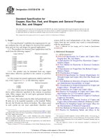
13.7.4 Rounded Edge—When specified in the contract or
purchase order, bar may be finished with edges rounded as
shown in Fig. 2, with a radius of curvature as shown in Table
13.
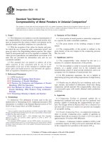
13.7.5 Full Rounded Edge—When specified in the contract
or purchase order, bar may be finished with substantially
uniform round edges, the radius of curvature being approximately one half the thickness of the product as shown in Fig.
3, but in no case to exceed one half the thickness of the product
by more than 25 %.
13.7.6 Shapes—Products with edge or corner contours other
than described in 13.7.1 – 13.7.5 are classified as shapes.
NOTE 2—For the purpose of determining conformance with the dimensional requirements prescribed in this specification, any measured value
outside the specified limiting values for any dimension may be cause for
rejection.
TABLE 11 Radius for Square Corners
Specified Thickness, in. [mm]
Maximum Radius Permissible for
Square Corners, in. [mm]
Up to 3⁄16 [5] incl.
Over 3⁄16 to 1 [5 to 25] incl.
Over 1 [25]
⁄ [0.4]
⁄ [0.8]
1⁄16 [1.6]
1 64
1 32
14. Specimen Preparation
14.1 Microscopical Examination—Specimen preparation
shall be in accordance with Procedure A of Test Methods B577.
15. Test Methods
13.7.2 Square Corners—Unless otherwise specified in the
contract or purchase order, bar shall be finished with commercially square corners with the maximum permissible radius
shown in Table 11.
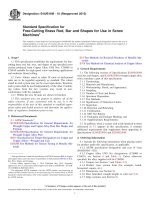
13.7.3 Rounded Corners—When specified in the contract or
purchase order, bar may be finished with corners rounded as
shown in Fig. 1 to a quarter circle with a radius as shown in
Table 12. The tolerance on the radius shall be 625 %.
15.1 Refer to Specification B249/B249M for the appropriate
mechanical test method.
15.2 In cases of disagreement, test methods for chemical
analysis shall be subject to agreement between the manufacturer or supplier and the purchaser. The following table is a list
of published methods, some of which may no longer be viable,
which along with others not listed, may be used subject to
agreement.
Element
Copper
Phosphorus
Selenium
Silver
Tellurium
ASTM Test Method
E53
E62
Refer to Annex, Specification B216
E478
Refer to Annex, Specification B216
15.2.1 For Copper No. C10100, refer to the Annex of
Specification B170 for test methods.
15.2.2 Test method(s) for the determination of element(s)
resulting from contractual or purchaser order agreement shall
be as agreed upon between the manufacturer or supplier and
the purchaser.
NOTE 1—The arc shall not necessarily be tangent at points, A, but the
product shall be commercially free from sharp, rough, or projecting edges.
FIG. 1 Rounded Corners
6
B187/B187M − 16
TABLE 13 Radius for Rounded Edge
TABLE 12 Radius for Rounded Corners
Nominal Radius of Corners, in. [mm]
Specified Thickness,
in. [mm]
For Widths Up
to and Including
2× Thickness
Up to 1⁄8 [2], incl.
1 64
Over ⁄ to ⁄ [2 to 6],
incl.
Over 3⁄16 to 1 [6 to 25],
incl.
Over 1 [25]
1 32
18
3 16
⁄
[0.4]
⁄
[0.8]
⁄
[1.6]
1 16
⁄ [3]
18
Specified Thickness,
in. [mm]
For Widths More
Than 2× Thickness
Up to 3⁄16 [5], incl.
Over 3⁄16 [5]
full rounded edges as
given in 13.7.5
1⁄32 [0.8]
⁄
1 16
Nominal Radius of
Rounded Edge,
in. [mm]
11⁄4 × thickness
11⁄4 × thickness
Tolerance on Radius,
Plus and Minus,
in. [mm]
1⁄2 × thickness
1⁄4 × thickness
[1.6]
⁄ [3]
18
NOTE 1—The arc shall not necessarily be tangent at points, A, but shall
be substantially symmetrical with the axis of the product, and the product
shall be commercially free from sharp, rough, or projecting edges.
FIG. 3 Full Rounded Edge
17. Keywords
NOTE 1—The arc shall be substantially symmetrical with the axis of the
product. The corners, A, will usually be sharp, but shall not have rough or
projecting edges.
17.1 bar; bus bar; copper; electrical conductors; embrittlement test; rod; shapes; UNS No. C10100; UNS No. C10200;
UNS No. C10300; UNS No. C10400; UNS No. C10500; UNS
No. C10700; UNS No. C10920; UNS No. C10930; UNS No.
C10940; UNS No. C11000; UNS No. C11300; UNS No.
C11400; UNS No. C11500; UNS No. C11600; UNS No.
C10800; UNS No. C12000; UNS No. C12200
FIG. 2 Rounded Edge
16. Certification
16.1 When product is ordered to meet the requirements of
the ASME Boiler and Pressure Vessel Code, the certification
requirements of Specification B249/B249M are mandatory.
SUPPLEMENTARY REQUIREMENTS
The following supplementary requirements shall apply only when specified by the purchaser in the
inquiry, contract, or order, for agencies of the U.S. government.
requirements specified. Except as otherwise specified in the
contract or purchase order, the manufacturer may use his own
or any other suitable facilities for the performance of the
inspection and test requirements unless disapproved by the
purchaser at the time the order is placed. The purchaser shall
have the right to perform any of the inspections or tests set
forth when such inspections and tests are deemed necessary to
ensure that the material conforms to prescribed requirements.
S1. Referenced Documents
S1.1 The following documents of the issue in effect on date
of material purchase form a part of this specification to the
extent referenced herein:
S1.1.1 Federal Standards:6
Fed. Std. No. 102 Preservation, Packaging and Packing
Levels
Fed. Std. No. 123 Marking for Shipment (Civil Agencies)
Fed. Std. No. 185 Identification Marking of Copper and
Copper-Base Alloy Mill Products
S1.1.2 Military Standards:6
MIL-STD-105 Sampling Procedures and Table for Inspection by Attributes
MIL-STD-129 Marking for Shipment and Storage
S1.1.3 Military Specification:6
S3. Identification Marking
S3.1 All material shall be properly marked for identification
in accordance with Fed. Std. No. 185 except that the ASTM
specification number and the alloy number shall be used.
S4. Preparation for Delivery
NOTE 3—MIL-C-3993, Packaging of Copper and Copper-Base Alloy
Mill Products, has been withdrawn and replaced by Practice B900.
S4.1 Preservation, Packaging, Packing:
S4.1.1 Military Agencies—The material shall be separated
by size, composition, grade or class and shall be preserved and
packaged, Level A or B as specified in the contract or purchase
order, in accordance with the requirements of Practice B900.
S4.1.2 Civil Agencies—The requirements of Fed. Std. No.
102 shall be referenced for definitions of the various levels of
packaging protection.
S4.2 Marking:
S2. Quality Assurance
S2.1 Responsibility for Inspection—Unless otherwise specified in the contract or purchase order, the manufacturer is
responsible for the performance of all inspection and test
6
Available from DLA Document Services, Building 4/D, 700 Robbins Ave.,
Philadelphia, PA 19111-5094, .
7
B187/B187M − 16
S4.2.1 Military Agencies—In addition to any special marking required by the contract or purchase order, marking for
shipment shall be in accordance with MIL-STD-129.
S4.2.2 Civil Agencies—In addition to any special marking
required by the contract or purchase order, marking for
shipment shall be in accordance with Fed. Std. No. 123.
APPENDIX
(Nonmandatory Information)
X1. RESISTIVITY
TABLE X1.1 Resistivity Relationships
Conductivity at
68°F, %
Ω·g/m2
Ω·lb/mile2
Ω·cmil/ft
Ω·mm2/m
µΩ·in.
µΩ·cm
101.0
100.0
99.37
98.40
98.35
98.16
97.40
96.16
92.20
0.151 76
866.53
10.268
0.017 070
0.672 07
1.7070
0.153 28
875.20
10.371
0.017 241
0.678 79
1.7241
0.15425
880.75
10.437
0.017350
0.68309
1.7350
0.155 77
889.42
10.539
0.017 521
0.689 81
1.7521
0.15585
889.88
10.54
0.017530
0.69018
1.7530
0.156 14
891.60
10.565
0.017 564
0.691 51
1.7564
0.157 37
898.55
10.648
0.017 701
0.696 90
1.7701
0.159 40
910.15
10.785
0.017 930
0.705 90
1.7930
0.16661
951.31
11.273
.018740
0.73782
1.8740
subject is contained in NBS Handbook 100 of the National
Institute of Standards Technology.7 Relationships that may be
useful in connection with the values of resistivity prescribed in
this specification are as shown in Table X1.1, each column
containing equivalent expressions at 20°C [68°F]:
X1.1 “Resistivity” is used in place of “conductivity.” The
value of 0.153 28 Ω·g/m2 at 20°C [68°F] is the international
standard for the resistivity of annealed copper equal to 100 %
conductivity. This term means that a wire 1 m in length and
weighing 1 g would have a resistance of 0.153 28 Ω. This is
equivalent to a resistivity value of 875.20 Ω·lb/mile2, which
signifies the resistance of a wire 1 mile in length weighing 1 lb.
It is also equivalent, for example, to 1.7241 µΩ/cm of length of
a bar 1 cm2 in cross section. A complete discussion of this
7
Available from National Institute of Standards and Technology (NIST), 100
Bureau Dr., Stop 1070, Gaithersburg, MD 20899-1070, .
SUMMARY OF CHANGES
Committee B05 has identified the location of selected changes to this standard since the last issue
(B187/B187M – 15) that may impact the use of this standard. (Approved April 1, 2016).
(1) Revised 15.2.
Committee B05 has identified the location of selected changes to this standard since the last issue
(B187/B187M – 11) that may impact the use of this standard. (Approved May 1, 2015).
(1) Corrected Temper Designation in Table 10.
Committee B05 has identified the location of selected changes to this standard since the last issue (B187 – 06)
that may impact the use of this standard. (Approved April 1, 2011).
(5) In Table 2 no mechanical values have been changed.
However, for Bar the temper H02 has replaced H04 since H02
more accurately describes those required values and conforms
to similar values found in B152.
(6) Added references to Practice B900 and Test Method E2575
to Section 2.
(7) Added new resistivity relationship values to non-mandatory
information in Appendix.
(1) All references to MIL C 3993 for Packaging of Copper and
Copper-Base Alloy Mill Products have been replaced by
Practice B900.
(2) The option has been given in Section 9.2 to use Test
Method E1004 in addition to Test Method B193.
(3) Section 11.2.2 has been added to allow the analysis of
oxygen content directly as an alternative to Test Method A.
(4) Resistivity limits have been established for C12000 in
Table 2.
8
B187/B187M − 16
ASTM International takes no position respecting the validity of any patent rights asserted in connection with any item mentioned
in this standard. Users of this standard are expressly advised that determination of the validity of any such patent rights, and the risk
of infringement of such rights, are entirely their own responsibility.
This standard is subject to revision at any time by the responsible technical committee and must be reviewed every five years and
if not revised, either reapproved or withdrawn. Your comments are invited either for revision of this standard or for additional standards
and should be addressed to ASTM International Headquarters. Your comments will receive careful consideration at a meeting of the
responsible technical committee, which you may attend. If you feel that your comments have not received a fair hearing you should
make your views known to the ASTM Committee on Standards, at the address shown below.
This standard is copyrighted by ASTM International, 100 Barr Harbor Drive, PO Box C700, West Conshohocken, PA 19428-2959,
United States. Individual reprints (single or multiple copies) of this standard may be obtained by contacting ASTM at the above
address or at 610-832-9585 (phone), 610-832-9555 (fax), or (e-mail); or through the ASTM website
(www.astm.org). Permission rights to photocopy the standard may also be secured from the Copyright Clearance Center, 222
Rosewood Drive, Danvers, MA 01923, Tel: (978) 646-2600; />
9