Astm b 160 05 (2014)
Bạn đang xem bản rút gọn của tài liệu. Xem và tải ngay bản đầy đủ của tài liệu tại đây (105.86 KB, 6 trang )
Designation: B160 − 05 (Reapproved 2014)
Standard Specification for
Nickel Rod and Bar1
This standard is issued under the fixed designation B160; the number immediately following the designation indicates the year of
original adoption or, in the case of revision, the year of last revision. A number in parentheses indicates the year of last reapproval. A
superscript epsilon (´) indicates an editorial change since the last revision or reapproval.
Among Brinell Hardness, Vickers Hardness, Rockwell
Hardness, Superficial Hardness, Knoop Hardness, Scleroscope Hardness, and Leeb Hardness
E1473 Test Methods for Chemical Analysis of Nickel,
Cobalt, and High-Temperature Alloys
1. Scope
2
3
1.1 This specification covers nickel (UNS N02200), low
carbon nickel (UNS N02201),3 and solution strengthened
nickel (UNS N02211) in the form of hot-worked and coldworked rod and bar in the conditions shown in Table 1.
1.2 The values stated in inch-pound units are to be regarded
as standard. The values given in parentheses are mathematical
conversions to SI units that are provided for information only
and are not considered standard.
1.3 This standard does not purport to address all of the
safety concerns, if any, associated with its use. It is the
responsibility of the user of this standard to become familiar
with all hazards including those identified in the appropriate
Material Safety Data Sheet (MSDS) for this product/material
as provided by the manufacturer, to establish appropriate
safety and health practices, and determine the applicability of
regulatory limitations prior to use.
3. Terminology
3.1 Definitions of Terms Specific to This Standard:
3.1.1 bar, n—material of rectangular (flats), hexagonal, or
square solid section up to and including 10 in. (254 mm) in
width and 1⁄8 in. (3.2 mm) and over in thickness in straight
lengths.
NOTE 1—Hot-worked rectangular bar in widths 10 in. (254 mm) and
under may be furnished as hot-rolled plate with sheared or cut edges in
accordance with Specification B162, provided the mechanical property
requirements of Specification B160 are met.
3.1.2 rod, n—material of round solid section furnished in
straight lengths.
2. Referenced Documents
2.1 ASTM Standards:4
B162 Specification for Nickel Plate, Sheet, and Strip
B880 Specification for General Requirements for Chemical
Check Analysis Limits for Nickel, Nickel Alloys and
Cobalt Alloys
E8 Test Methods for Tension Testing of Metallic Materials
E18 Test Methods for Rockwell Hardness of Metallic Materials
E29 Practice for Using Significant Digits in Test Data to
Determine Conformance with Specifications
E140 Hardness Conversion Tables for Metals Relationship
4. Ordering Information
4.1 It is the responsibility of the purchaser to specify all
requirements that are necessary for the safe and satisfactory
performance of material ordered under this specification.
Examples of such requirements include, but are not limited to,
the following:
4.1.1 ASTM designation and year of issue.
4.1.2 UNS number.
4.1.3 Section—Rod (round) or bar (square, hexagonal, or
rectangular).
4.1.4 Dimensions—Dimensions including length.
4.1.5 Condition.
4.1.6 Finish.
4.1.7 Quantity—feet or number of pieces.
4.1.8 Certification—State if certification or a report of test
results is required (Section 15).
4.1.9 Samples for Product (Check) Analysis—State whether
samples for product (check) analysis should be furnished.
4.1.10 Purchaser Inspection—If purchaser wishes to witness tests or inspection of material at place of manufacture, the
purchase order must so state indicating which test or inspections are to be witnessed.
1
This specification is under the jurisdiction of ASTM Committee B02 on
Nonferrous Metals and Alloys and is the direct responsibility of Subcommittee
B02.07 on Refined Nickel and Cobalt and Their Alloys.
Current edition approved Oct. 1, 2014. Published October 2014. Originally
approved in 1941. Last previous edition approved in 2009 as B160 – 05 (2009)ε1.
DOI: 10.1520/B0160-05R14.
2
For ASME Boiler and Pressure Vessel Code applications see related Specification SB-160 in Section II of that Code.
3
New designations established in accordance with ASTM E527 and SAE J1086,
Practice for Numbering Metals and Alloys (UNS).
4
For referenced ASTM standards, visit the ASTM website, www.astm.org, or
contact ASTM Customer Service at For Annual Book of ASTM
Standards volume information, refer to the standard’s Document Summary page on
the ASTM website.
Copyright © ASTM International, 100 Barr Harbor Drive, PO Box C700, West Conshohocken, PA 19428-2959. United States
1
B160 − 05 (2014)
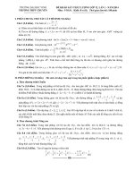
TABLE 1 Mechanical Properties
Condition and Diameter or Distance
Between Parallel Surfaces, in. (mm)
Tensile Strength, min,
psi (MPa)
Yield Strength (0.2 % offset),
min. psi (MPa)A
Elongation in 2 in. or 50
mm or 4D, min %
Nickel (UNS N02200)
Cold-worked (as worked):
Rounds, 1 (25.4) and under
80 000 (550)
60 000 (415)
Rounds over 1 to 4 (25.4 to 101.6) incl.
75 000 (515)
50 000 (345)
Squares, hexagons, and rectangles, all sizes
65 000 (450)
40 000 (275)
Hot-worked:
All sections, all sizes
60 000 (415)
15 000 (105)
Rings and disksD
—
—
Annealed:
Rods and bars, all sizes
55 000 (380)
15 000 (105)
Rings and disksE
—
—
Forging quality
F
F
All sizes
Low-Carbon Nickel (UNS N02201) and Solution Strengthened Nickel (UNS N02211)
Hot-worked:
All sections, all sizes
50 000 (345)
10 000 (70)
Annealed:
All products, all sizes
50 000 (345)
10 000 (70)
10B
15
25B
35C
—
40B
—
F
40C
40B
A
See 12.2.
Not applicable to diameters or cross sections under 3⁄32 in. (2.4 mm).
C
For hot-worked flats 5⁄16 in. (7.9 mm) and under in thickness the elongation shall be 25 %, min.
D
Hardness B45 to B80, or equivalent.
E
Hardness B45 to B70 or equivalent.
F
Forging quality is furnished to chemical requirements and surface inspection only. No tensile properties are required.
B
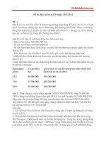
TABLE 3 Permissible Variations in Diameter or Distance Between
Parallel Surfaces of Cold-Worked Rod and Bar
5. Chemical Composition
5.1 The material shall conform to the composition limits
specified in Table 2.
Specified Dimension, in. (mm)A
+
5.2 If a product (check) analysis is performed by the
purchaser, the material shall be done per Specification B880
and the material shall conform to the product (check) analysis
variations defined in Check Analysis Variation table of Specification B880.
Rounds:
1⁄16 (1.6) to 3⁄16 (4.8), excl
3⁄16 (4.8) to 1⁄2 (12.7), excl
1⁄2 (12.7) to 15⁄16 (23.8), incl
Over 15⁄16 (23.8) to 115⁄16 (49.2), incl
Over 115⁄16 (49.2) to 21⁄2 (63.5), incl
Over 21⁄2 (63.5) to 3 (76.2), incl
Over 3 (76.2) to 3 (88.9), incl
Over 31⁄2 (88.9) to 4 (101.6), incl
Hexagons, squares, rectangles:
1⁄2 (12.7) and less
Over 1⁄2 (12.7) to 7⁄8 (22.2), incl
Over 7⁄8 (22.2) to 11⁄4 (31.8), incl
Over 11⁄4 (31.8) to 21⁄4 (57.2), incl
Over 21⁄4 (57.2) to 3 (76.2), incl
Over 3 (76.2) to 31⁄2 (88.9), incl
Over 31⁄2 (88.9) to 4 (101.6), incl
6. Mechanical and Other Requirements
6.1 Mechanical Properties—The material shall conform to
the mechanical properties specified in Table 1.
7. Dimensions and Permissible Variations
7.1 Diameter, Thickness, or Width—The permissible variations from the specified dimensions as measured on the
diameter or between parallel surfaces of cold-worked rod and
bar shall be as prescribed in Table 3, and of hot-worked rod and
bar as prescribed in Table 4.
Nickel, minA
Copper, max
Iron, max
Manganese, max
Carbon, max
Silicon, max
Sulfur, max
A
Low-Carbon
Nickel (UNS
N02201)
Solution
Strengthened
Nickel (UNS
N02211)
99.0
0.25
0.40
0.35
0.15†
0.35
0.01
99.0
0.25
0.40
0.35
0.02
0.35
0.01
93.7
0.25
0.75
4.25 – 5.25
0.20†
0.15
0.015
0
0
0.001 (0.03)
0.0015 (0.04)
0.002 (0.05)
0.0025 (0.06)
0.003 (0.08)
0.0035 (0.09)
0.002
0.003
0.002
0.003
0.004
0.005
0.006
0.007
(0.05)
(0.08)
(0.05)
(0.08)
(0.10)
(0.13)
(0.15)
(0.18)
0
0
0
0
0
0
0
0.004 (0.10)
0.005 (0.13)
0.007 (0.18)
0.009 (0.23)
0.011 (0.28)
0.015 (0.38)
0.017 (0.43)
7.2 Out-of-Round—Hot-worked rods and cold-worked rods
(except “forging quality”), all sizes, in straight lengths, shall
not be out-of-round by more than one half the total permissible
variations in diameter shown in Tables 3 and 4, except for
hot-worked rods 1⁄2 in. (12.7 mm) in diameter and under, which
may be out-of-round by the total permissible variations in
diameter shown in Table 4.
Composition Limits, %
Nickel (UNS
N02200)
−
A
Dimensions apply to diameter of rounds, to distance between parallel surfaces of
hexagons and squares, and separately to width and thickness of rectangles.
TABLE 2 Chemical Requirements
Element
Permissible Variations from
Specified Dimension, in. (mm)
7.3 Corners—Cold-worked bars will have practically exact
angles and sharp corners.
7.4 Machining Allowances for Hot-Worked Materials—
When the surfaces of hot-worked products are to be machined,
the allowances prescribed in Table 5 are recommended for
normal machining operations.
Element shall be determined arithmetically by difference.
† Carbon max value for UNS N02200 was corrected editorially.
† Carbon max value for UNS N02211 was corrected editorially.
2
B160 − 05 (2014)
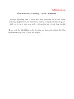
TABLE 4 Permissible Variations in Diameter or Distance Between
Parallel Surfaces of Hot-Worked Rod and Bar
Specified Dimension, in. (mm)A
Permissible Variations from
Specified Dimensions, in. (mm)
+
Rod and bar, hot-worked:
1 (25.4) and under
Over 1 (25.4) to 2 (50.8), incl
Over 2 (50.8) to 4 (101.6), incl
Over 4 (101.6)
Rod, rough-turned or rough-ground:
Under 1 (25.4)
1 (25.4) and over
Forging quality rod:B
Under 1 (25.4)
1 (25.4) and over
9.2.1 A lot for mechanical properties testing shall consist of
all material from the same heat, nominal diameter of thickness,
and condition.
9.2.1.1 Where material cannot be identified by heat, a lot
shall consist of not more than 500 lb (227 kg) of material in the
same size and condition.
0.016
0.031
0.047
0.125
(0.41)
(0.79)
(1.19)
(3.18)
−
0.016
0.016
0.031
0.063
(0.41)
(0.41)
(0.79)
(1.60)
0.005 (0.13)
0.031 (0.79)
0.005 (0.13)
0
0.005 (0.13)
0.031 (0.79)
0.005 (0.13)
0
9.3 Test Material Selection:
9.3.1 Chemical Analysis—Representative samples from
each lot shall be taken during pouring or subsequent processing.
9.3.1.1 Product (check) analysis shall be wholly the responsibility of the purchaser.
9.3.2 Mechanical Properties—Samples of the material to
provide test specimens for mechanical properties shall be taken
from such locations in each lot as to be representative of that
lot.
A
Dimensions apply to diameter of rods, to distance between parallel surfaces of
hexagons and squares, and separately to width and thickness of rectangles.
B
Spot grinding is permitted to remove minor surface imperfections. The depth of
these spot ground areas shall not exceed 3 % of the diameter of the rod.
10. Number of Tests
10.1 Chemical Analysis—One test per lot.
7.5 Length—The permissible variations in length of coldworked and hot-worked rod and bar shall be as prescribed in
Table 6.
7.5.1 Rods and bars ordered to random or nominal lengths
will be furnished with either cropped or saw-cut ends; material
ordered to cut lengths will be furnished with square saw-cut or
machined ends.
10.2 Tension—One test per lot.
10.3 Hardness—One test per lot.
11. Specimen Preparation
11.1 Tension test specimens shall be taken from material in
the final condition and tested in the direction of fabrication.
11.1.1 All rod and bar shall be tested in full cross-section
size when possible. When a full cross-section size test cannot
be performed, the largest possible round specimen shown in
Test Methods E8 shall be used. Longitudinal strip specimens
shall be prepared in accordance with Test Methods E8 for
rectangular bar up to 1⁄2 in. (12.7 mm), inclusive, in thicknesses
that are too wide to be pulled full size.
7.6 Straightness:
7.6.1 The permissible variations in straightness of coldworked rod and bar as determined by the departure from
straightness shall be as prescribed in Table 7.
7.6.2 The permissible variations in straightness of precision
straightened cold-worked rod as determined by the departure
from straightness shall be as prescribed in Table 8.
7.6.2.1 In determining straightness in the standard 42-in.
(1.07-m) distance between supports or, when specified, in
determining straightness in lengths not in excess of those
shown in Table 8, the rod shall be placed on a precision table
equipped with ballbearing rollers and a micrometer or dial
indicator. The rod shall then be rotated slowly against the
indicator, and the deviation from straightness in any portion of
the rod between the supports shall not exceed the permissible
variations prescribed in Table 8. The deviation from straightness (throw in one revolution) is defined as the difference
between the maximum and minimum readings of the dial
indicator in one complete revolution of the rod.
7.6.3 The permissible variations in straightness of hotworked rod and bar as determined by the departure from
straightness shall be as specified in Table 9.
11.2 Hardness test specimens shall be taken from material in
the final condition.
11.3 In order that the hardness determinations may be in
reasonable close agreement, the following procedure is suggested:
11.3.1 For rod, under 1⁄2 in. (12.7 mm) in diameter, hardness
readings shall be taken on a flat surface prepared by filing or
grinding approximately 1⁄16 in. (1.6 mm) from the outside
surface of the rod.
11.3.2 For rod, 1⁄2 in. (12.7 mm) in diameter and larger, and
for hexagonal, square, and rectangular bar, all sizes, hardness
readings shall be taken on a cross section midway between the
surface and center of the section.
12. Test Methods
12.1 The chemical composition, mechanical, and other
properties of the material as enumerated in this specification
shall be determined, in case of disagreement, in accordance
with the following methods:
8. Workmanship, Finish, and Appearance
8.1 The material shall be uniform in quality and condition,
smooth, commercially straight or flat, and free of injurious
imperfections.
Test
Chemical Analysis
Tension
Rockwell Hardness
Hardness Conversion
Rounding Procedure
9. Sampling
9.1 Lot—Definition:
9.2 A lot for chemical analysis shall consist of one heat.
3
ASTM Designation
E1473
E8
E18
E140
E29
B160 − 05 (2014)
TABLE 5 Normal Machining Allowances for Hot-worked Material
Normal Machining Allowance, in. (mm)
Finished-Machined Dimensions for Finishes as
Indicated Below, in. (mm)A
Distance Between
Parallel Surface, for
Hexagonal and
Square Bar
On Diameter,
for Rods
For Rectangular Bar
On Thickness
On Width
B
Hot-worked:
Up to 7⁄8 (22.2), incl
Over 7⁄8 to 17⁄8 (22.2 to 47.6), incl
Over 17⁄8 to 27⁄8 (47.6 to 73.0), incl
Over 27⁄8 to 313⁄16 (73.0 to 96.8), incl
Over 313⁄16 (96.8)
Hot-worked rods:
Rough-turned or Rough-ground:C
15⁄16 to 4 (23.8 to 101.6), incl in diameter
Over 4 to 12 (101.6 to 304.8), incl in
diameter
⁄ (3.2)
⁄ (3.2)
3⁄16 (4.8)
1⁄4 (6.4)
1⁄4 (6.4)
⁄ (3.2)
⁄ (4.8)
1⁄4 (6.4)
—
—
⁄ (3.2)
⁄ (3.2)
—
—
—
⁄ (4.8)
⁄ (4.8)
3⁄16 (4.8)
3⁄16 (4.8)
3⁄8 (9.5)
18
18
18
3 16
18
3 16
18
3 16
⁄ (1.6)
⁄ (3.2)
—
—
1 16
18
—
—
—
A
Dimensions apply to diameter of rods, to distance between parallel surfaces of hexagonal and square bar, and separately to width and thickness of rectangular bar.
The allowances for hot-worked material in Table 5 are recommended for rods machined in lengths of 3 ft (0.91 m) or less and for bars machined in lengths of 2 ft (0.61
m) or less. Hot-worked material to be machined longer lengths should be specified showing the finished cross-sectional dimension and the length in which the material
will be machined in order that the manufacturer may supply material with sufficient oversize, including allowance for out-of-straightness.
C
Applicable to 3 ft (0.91 m) max length.
B
TABLE 6 Permissible Variations in Length of Rods and Bars
Random mill lengths:
Hot-worked
Cold-worked
Multiple lengths
Nominal lengths
Cut lengths
6 to 24 ft (1.83 to 7.31 m) long with not more than 25 weight % between 6 and 9 ft (1.83 and 2.74 m)A
6 to 20 ft (1.83 to 6.1 m) long with not more than 25 weight % between 6 and 10 ft (1.83 and 3.05 m).
Furnished in multiples of a specified unit length, within the length limits indicated above. For each multiple, an
allowance of 1⁄4 in. (6.4 mm) will be made for cutting, unless otherwise specified. At the manufacturer’s option,
individual specified unit lengths may be furnished.
Specified nominal lengths having a range of not less than 2 ft (610 mm) with no short lengths allowed.B
A specified length to which all rods and bars will be cut with a permissible variation of +1⁄8 in. (3.2 mm), − 0 for sizes 8
in. (203 mm) and less in diameter or distance between parallel surfaces. For larger sizes, the permissible variation
shall be +1⁄4 in. (6.4 mm), − 0.
A
For hot-worked sections weighing over 25 lb/ft (37 kg/m) and for smooth forged products, all sections, short lengths down to 2 ft (610 mm) may be furnished.
For cold-worked rods and bars under 1⁄2 in. (12.7 mm) in diameter or distance between parallel surfaces ordered to nominal or stock lengths with a 2-ft (610 mm) range,
at least 93 % of such material shall be within the range specified; the balance may be in shorter lengths but in no case shall lengths less than 4 ft (1220 mm) be furnished.
B
TABLE 7 Permissible Variations in Straightness Of Cold-Worked
Rods And Bars
Specified Diameter or Distance
Between Parallel Surfaces, in.
(mm)A
Rounds:
1⁄2 (12.7) to 4 (101.6), incl
Hexagons, squares, rectangles:
1⁄2 (12.7) to 4 (101.6), incl
Permissible Variations in Lengths
Indicated, in. (mm)
Depth of Chord:
0.030 (0.76) per ft (305 mm) of length
0.030 (0.76) per ft (305 mm) of length
A
Material under 1⁄2 in. (12.7 mm) shall be reasonably straight and free of sharp
bends and kinks.
12.2 For purposes of determining compliance with the
specified limits for requirements of the properties listed in the
following table, an observed value or a calculated value shall
be rounded as indicated below, in accordance with the rounding method of Practice E29:
Test
Chemical composition, hardness, and
tolerances (when expressed in
decimals)
Tensile strength and yield strength
Elongation
13. Inspection
13.1 Inspection of the material shall be made as agreed upon
between the manufacturer and the purchaser as part of the
purchase contract.
Rounded Unit for Observed
Or Calculated Value
Nearest unit in the last right-hand place
of figures of the specified limit. If two
choices are possible, as when the
digits dropped are exactly a 5, or a 5
followed only by zeros, choose the one
ending in an even digit, with zero
defined as an even digit.
Nearest 1000 psi (6.9 MPa)
Nearest 1 %
14. Rejection and Rehearing
14.1 Material that fails to conform to the requirements of
this specification may be rejected. Rejection should be reported
to the producer or supplier promptly and in writing. In case of
dissatisfaction with the results of the test, the producer or
supplier may make claim for a rehearing.
4
B160 − 05 (2014)
TABLE 8 Permissible Variations in Straightness of Precision-Straightened Cold-Worked Nickel (UNS N02200) Shafting
Specified Diameter of
Shafting, in.
⁄ to 15⁄16 , incl
Over 15⁄16 to 115⁄16 , incl
Over 115⁄16 to 21⁄2 , incl
Over 21⁄2 to 4, incl
3⁄4 to 15⁄16 , incl
Over 15⁄16 to 4, incl
Specified Diameter of
Shafting, mm
12.7 to 23.8 incl
Over 23.8 to 49.2, incl
Over 49.2 to 63.5, incl
Over 63.5 to 101.6, incl
19.1 to 23.8 incl
Over 23.8 to 101.6, incl
12
Standard Distance Between
Supports
Permissible Variations (Throw in One Revolution)
from Straightness, in.
42 in.
42 in.
42 in.
42 in.
Specified lengths of 3 to 10 ft
Specified lengths of 20 ft and less
Standard Distance Between
Supports
1067 mm
1067 mm
1067 mm
1067 mm
specified lengths of 914 to 3050 mm
specified lengths of 6100 mm and less
0.005
0.006
0.007
0.008
0.004 + 0.0025 for each foot or fraction thereof in excess of 3 ft.
0.005 + 0.0015 for each foot or fraction thereof in excess of 3 ft.
Permissible Variations (Throw in One Revolution)
from Straightness, mm
0.13
0.15
0.18
0.20
10.2 + 0.2 for each metre or fraction thereof in excess of 914 mm
12.7 + 0.13 for each metre or fraction thereof in excess of 914 mm
TABLE 9 Permissible Variations in Straightness of Hot-Worked
Rods and BarsA
Finish
Rods and bars, hot-worked
Rounds—hot-worked, rough-ground, or rough-turned
Permissible
Variations, in./ft.
(mm/m)B
0.050 (4.2)C
0.050 (4.2)C
A
Not applicable to forging quality.
Material under 1⁄2 in. (12.7 mm) shall be reasonably straight and free of sharp
bends and kinks.
C
The maximum curvature (depth of chord) shall not exceed the values indicated
multiplied by the length in feet.
B
15. Certification
attached thereto: The name of the material or UNS Number,
heat number, condition (temper), ASTM Specification B160,
the size, gross, tare, and net weight, consignor and consignee
address, contract or order number, or such other information as
may be defined in the contract or order.
15.1 When specified in the purchase order or contract, a
manufacturer’s certification shall be furnished to the purchaser
stating that material has been manufactured, tested, and inspected in accordance with this specification, and that the test
results on representative samples meet specification requirements. When specified in the purchase order or contract, a
report of the test results shall be furnished.
17. Keywords
17.1 bar; rod; N02200; N02201; N02211
16. Product Marking
16.1 The following information shall be marked on the
material or included on the package, or on a label or tag
APPENDIX
(Nonmandatory Information)
X1. CONDITIONS AND FINISHES
X1.1 The various conditions and finishes in which nickel
(UNS N02200) and low-carbon nickel (UNS N02201) rods and
bars are procurable are as indicated below.
X1.2.2 Hot-Worked Rough-Ground—Similar to X1.2.1 except rough-ground.
X1.2.3 Hot-Worked, Rough-Turned—Similar to X1.2.1 except rough-turned with a broad-nosed tool similar to a bar
peeling operation and thus may not be straight. Intended
generally for machining where an overhauled surface is
desired, essentially for machined step down shafts or parts
machined in short lengths of 3 ft (914 mm) or less.
X1.2 Low-carbon nickel (UNS N02201) is intended essentially for fused caustic and other fused salts and for temperatures above 600°F (316°C). For such applications the manufacturer should be consulted.
X1.2.1 Hot-Worked—With a tightly adherent, black, mill
oxide surface.
5
B160 − 05 (2014)
better surface inspection than does hot-worked material and
often employed where welding is involved where removal of
mill oxide is desired.
X1.2.4 Hot-Worked Forging Quality—Rough-turned and
spot-ground, as necessary, for sizes 1 in. (25.4 mm) in diameter
and over; rough-ground and spot-ground for sizes under 1 in. in
diameter. Material is selected from heats of known, good hot
malleability.
NOTE X1.2—Annealing prior to pickling may be required in order to
reduce the mill oxide since uniform pickling of an unreduced oxide is
difficult.
NOTE X1.1—For sizes 4 in. (101.6 mm) in diameter and less, coldworked rod may be used also for forging by virtue of the fact such rod
have been overhauled for removal of mechanical surface defects prior to
cold drawing. In such cases, the user should run pilot forging tests to
ensure himself that such material has the desired hot-malleability range.
X1.2.7 Cold-Worked, As-worked—Hot-worked overhauled,
cold-worked, and straightened with a smooth bright finish.
X1.2.8 Cold-worked Annealed—Hot-worked overhauled,
cold-worked, and straightened. Annealed for softness and with
a dull matte finish.
X1.2.5 Hot-Worked, Annealed—Soft with a tightly adherent
oxide that may vary from dark to light.
X1.2.6 Hot-Worked, Annealed and Pickled—Same as
X1.2.5 except descaled for removal of mill oxide. Provides for
ASTM International takes no position respecting the validity of any patent rights asserted in connection with any item mentioned
in this standard. Users of this standard are expressly advised that determination of the validity of any such patent rights, and the risk
of infringement of such rights, are entirely their own responsibility.
This standard is subject to revision at any time by the responsible technical committee and must be reviewed every five years and
if not revised, either reapproved or withdrawn. Your comments are invited either for revision of this standard or for additional standards
and should be addressed to ASTM International Headquarters. Your comments will receive careful consideration at a meeting of the
responsible technical committee, which you may attend. If you feel that your comments have not received a fair hearing you should
make your views known to the ASTM Committee on Standards, at the address shown below.
This standard is copyrighted by ASTM International, 100 Barr Harbor Drive, PO Box C700, West Conshohocken, PA 19428-2959,
United States. Individual reprints (single or multiple copies) of this standard may be obtained by contacting ASTM at the above
address or at 610-832-9585 (phone), 610-832-9555 (fax), or (e-mail); or through the ASTM website
(www.astm.org). Permission rights to photocopy the standard may also be secured from the Copyright Clearance Center, 222
Rosewood Drive, Danvers, MA 01923, Tel: (978) 646-2600; />
6