Astm b 851 04 (2014)
Bạn đang xem bản rút gọn của tài liệu. Xem và tải ngay bản đầy đủ của tài liệu tại đây (246.73 KB, 9 trang )
Designation: B851 − 04 (Reapproved 2014)
Standard Specification for
Automated Controlled Shot Peening of Metallic Articles
Prior to Nickel, Autocatalytic Nickel, or Chromium Plating,
or as Final Finish1
This standard is issued under the fixed designation B851; the number immediately following the designation indicates the year of
original adoption or, in the case of revision, the year of last revision. A number in parentheses indicates the year of last reapproval. A
superscript epsilon (´) indicates an editorial change since the last revision or reapproval.
B320 Practice for Preparation of Iron Castings for Electroplating
B322 Guide for Cleaning Metals Prior to Electroplating
B607 Specification for Autocatalytic Nickel Boron Coatings
for Engineering Use
B650 Specification for Electrodeposited Engineering Chromium Coatings on Ferrous Substrates
B656 Guide for Autocatalytic (Electroless) NickelPhosphorus Deposition on Metals for Engineering Use
(Discontinued 2000) (Withdrawn 2000)3
B689 Specification for Electroplated Engineering Nickel
Coatings
B733 Specification for Autocatalytic (Electroless) NickelPhosphorus Coatings on Metal
E11 Specification for Woven Wire Test Sieve Cloth and Test
Sieves
E165 Practice for Liquid Penetrant Examination for General
Industry
E709 Guide for Magnetic Particle Testing
2.2 Federal Standards:4
QQ-N-290 Nickel Plating (Electrodeposited)
QQ-C-320 Chromium Plating (Electrodeposited)
2.3 Military Standards:4
MIL-S-851 Steel Grit, Shot, and Cut Wire Shot, and Iron
Grit and Shot Blast Cleaning and Peening
MIL-S-13165 Shot Peening of Metal Parts
MIL-C-26074 Coating, Electroless Nickel
MIL-STD-45662 Calibration System Requirements
2.4 SAE Standards:5
SAE J441 Cut Steel Wire Shot
SAE J442 Test Strip, Holder and Gage for Shot Peening
SEA J827 Cast Steel Shot
SAE J1830 Size, Classification and Characteristics of Ceramic Shot for Peening
1. Scope
1.1 This specification covers the requirements for
automated, controlled shot peening of metallic articles prior to
electrolytic or autocatalytic deposition of nickel or chromium,
or as a final finish, using shot made of cast steel, conditioned
cut wire, or ceramic media. The process is applicable to those
materials on which test work has shown it to be beneficial
within given intensity ranges. It is not suitable for brittle
materials. Hand peening and rotary flap peening are excluded
specifically.
1.2 Shot peening induces residual compressive stresses in
the surface and near-surface layers of metallic articles, controlling or limiting the reduction in fatigue properties that occurs
from nickel or chromium plating of the article, or the fatigue
properties of unplated articles.
1.3 The values stated in SI units are to be regarded as
standard. No other units of measurement are included in this
standard.
1.4 This standard does not purport to address all of the
safety concerns, if any, associated with its use. It is the
responsibility of the user of this standard to establish appropriate safety and health practices and determine the applicability of regulatory limitations prior to use.
2. Referenced Documents
2.1 ASTM Standards:2
B183 Practice for Preparation of Low-Carbon Steel for
Electroplating
B242 Guide for Preparation of High-Carbon Steel for Electroplating
1
This specification is under the jurisdiction of ASTM Committee B08 on
Metallic and Inorganic Coatings and is the direct responsibility of Subcommittee
B08.02 on Pre Treatment.
Current edition approved Nov. 1, 2014. Published November 2014. Originally
approved in 1994. Discontinued January 2004 and reinstated in 2004 as B851–04.
Last previous edition approved in 2009 as B851–09. DOI: 10.1520/B0851-04R14.
2
For referenced ASTM standards, visit the ASTM website, www.astm.org, or
contact ASTM Customer Service at For Annual Book of ASTM
Standards volume information, refer to the standard’s Document Summary page on
the ASTM website.
3
The last approved version of this historical standard is referenced on
www.astm.org.
4
Available from Standardization Documents Order Desk, Bldg. 4 Section D, 700
Robbins Ave., Philadelphia, PA 19111-5094, Attn: NPODS.
5
Available from Society of Automotive Engineers, 400 Commonwealth Drive,
Warrendale, PA 15096.
Copyright © ASTM International, 100 Barr Harbor Drive, PO Box C700, West Conshohocken, PA 19428-2959. United States
1
B851 − 04 (2014)
3. Terminology
3.1 Definitions:
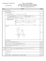
3.1.1 Almen strip—UNS G10700 carbon steel specimens
that are used to calibrate the energy of a shot peening stream
(see Fig. 1).
3.1.2 Almen strip holding fixture—a fixture for holding
Almen strips in suitable locations that represent the position
and angular orientation of the surfaces of a part where intensity
is to be determined and verified (see Fig. 2).
3.1.3 arc height—flat Almen strips, when subjected to a
stream of shot moving at an adequate velocity, bending in an
arc corresponding to the amount of energy transmitted by the
shot stream. The height of the curved arc measured in
millimeters is the arc height, measured by an Almen gage (see
Fig. 3).
3.1.4 automatic equipment—shot peening equipment in
which parts, fixtures, nozzles, and peening parameters are
preset by hand or by locating fixtures and verified by inspection
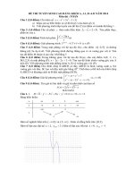
FIG. 2 Assembled Test Strip and Holder
FIG. 3 Almen Gage
personnel. The peening time is monitored automatically, and
the air pressure or wheel speed is set manually.
3.1.5 compressive stresses—cold working or stretching the
surface beyond the elastic limit by shot peening, creating a
layer in compression below the surface. The depth of compressive stresses is measured by the crown of the dimple to the
depth.
3.1.6 coverage—the extent of obliteration of the original
surface by dimples produced by impact from individual shot
particles and expressed as a percentage. See Note 1.
3.1.7 depth of compressive stresses—where the stress profile
passes through 0 stress.
3.1.8 intensity—the Almen strip arc height at saturation. Arc
height is not termed intensity correctly unless saturation is
achieved.
3.1.9 liquid tracer system—a liquid coating material bearing
a pigment that fluoresces under an ultraviolet light and removes
at a rate proportioned to peening coverage.
3.1.10 microprocessor-controlled equipment—peening
equipment that has nozzle holding fixtures and is computer
FIG. 1 Almen Test Specimen
2
B851 − 04 (2014)
4.8 Whether magnetic particle or penetrant inspection is
required before peening (see 7.2).
controlled for processing, monitoring, and documentation of
the peening parameters critical to process certification.
3.1.11 nozzle holding fixture—a fixture that holds the
nozzles at the required location, distance, and angle in a locked
position during the peening operation.
3.1.12 process interrupt parameters—for critical peening
operations, parameters such as shot flow, air pressure, part
r/min, oscillation rate, and cycle time that must be monitored
within process requirements.
3.1.13 saturation—the minimum duration of peening necessary to achieve the desired Almen intensity which, when
doubled, does not increase the Almen strip arc height by more
than 10 %.
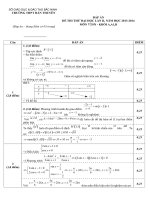
3.1.14 saturation curve—a curve that plots peening time on
the Almen strip (abscissa) versus Almen strip arc height
(ordinate) achieved for the peening time (see Fig. 4).
3.1.15 surface obliteration—the condition of a peened surface in which 100 % of the surface has been dimpled with shot
impressions.
4.9 Amount (percent) of coverage required in the areas to be
peened. A complete coverage is the minimum requirement (see
3.1.6 and 8.3).
4.10 Method for measuring coverage (see 8.3.1).
4.11 Type of equipment to be used, automated or computermonitored microprocessor (see 6.3 and X1.10 – X1.12).
4.12 Details of any post treatment such as corrosion protection (see 9.5).
4.13 Requirements of certification and test records, as
specified in Section 10.
5. Significance and Use
5.1 Shot peening is a process for cold working surfaces by
bombarding the product with shot of a solid and spherical
nature propelled at a relatively high velocity. In general, shot
peening will increase the fatigue life of a product that is subject
to bending or torsional stress. It will improve resistance to
stress corrosion cracking. It can be used to form parts or correct
their shapes. See Appendix X1 for additional information.
NOTE 1—A100 % coverage is defined as that leaving unpeened 2 % or
less of the original surface because the estimation of coverage of the
impressions is difficult when this is approximately 98 % of the total
surface. The 100 % coverage is a theoretical limiting value. Hence, the
term complete coverage is preferred. Complete coverage usually requires
increasing the base time, that is, the time of peening to reach 98 %
coverage, by 15 to 20 %. Values of 200 %, 300 %, etc. are obtained by
multiplying this run time by 2, 3, etc.
5.2 It is essential that the shot peening process parameters
be controlled rigidly to ensure repeatability from part to part
and lot to lot.
5.3 This specification covers techniques and methods necessary for proper control of the shot peening process.
4. Ordering Information
6. Materials and Equipment
4.1 When ordering articles to be shot peened, the purchaser
shall state the following:
6.1 Shot Material Composition:
6.1.1 Cast Steel—Cast steel shot shall conform to the
requirements of SAE J827.
6.1.2 Cut Wire—Cut wire shot shall be made from cold
finished, round wire, confirming to SAE J441.
6.1.3 Ceramic Shot—Ceramic beads shall conform to the
chemical composition given in Table 1 and to SAE J1830.
6.1.4 Shot Form and Shape:
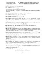
6.1.4.1 Cast Steel—Cast steel shot shall be spherical in
shape and free of sharp edges, corners, and broken pieces. It
shall conform to the acceptable shapes given in Fig. 5. The
number of nonconforming shapes (see Fig. 6) shall not exceed
the values given in Table 2.
6.1.4.2 Cut Wire—Cut wire shot shall be spherical in shape.
It shall be free of sharp edges, corners, and broken pieces. The
number of nonconforming shapes shall not exceed the values
given in Table 2.
6.1.4.3 Ceramic Shot—Ceramic shot shall be spherical in
shape and free of sharp edges, corners, and broken pieces. The
number of nonconforming shapes shall not exceed the values
given in Table 2.
4.2 ASTM designation.
4.3 Type, size, and hardness of shot to be used (see 6.1).
4.4 Number and frequency of the determinations of shot
size and uniformity required, if other than those specified in
8.1.1.
4.5 Peening intensity to be used at each location (see 8.2).
4.6 Number, frequency, and locations of Almen test specimens to be provided for intensity verification and monitoring
of the process if other than those specified in 8.2, 8.2.1, and
8.2.2.
4.7 Areas on the part that are to be shot peened and those to
be protected from the peening (see 7.5).
TABLE 1 Composition of Ceramic Shot
ZrO2 , %
SiO2 ,%
60.0–70.0 28.0–33.0
FIG. 4 Saturation Curve
3
Al2 O3 , %
Fe2 O3 , %
Free Iron, %
10.0 max
0.1 max
0.1 max
Specific
Gravity,
g/cm 3
3.60–3.95
B851 − 04 (2014)
6.1.6 Size:
(1) The size of the media shall be capable of producing the
required intensity in the required time.
(2) If a peened surface contains a fillet, the nominal size of
the shot shall not exceed one-half of the radius of the fillet.
(3) If the shot must pass through an opening, such as a slot,
to reach a peened surface the nominal diameter of the shot shall
not exceed one-fourth of the width or the diameter of the
opening.
6.1.6.1 Cast Steel—Cast steel shot charged into a machine
shall conform to the screen requirements given in Table 4 for
the nominal size selected. When a machine has a completely
new charge of cast steel shot, conditioning shall be conducted,
to remove the oxide layers on the shots, by bombarding onto a
hardened steel surface for a minimum of two passes. Conditioning may not be required if the addition to the charge
already in the machine is below 25 %. If the addition of over
25 % is made to the charge, conditioning is required.
6.1.6.2 Cut Wire—The diameter of cut wire shot charged
into a machine shall conform to the requirements given in
Table 4. Cut wire shot shall conform to the requirements of
length and cumulative weight given in Table 5. It is mandatory
that only preconditioned cut wire shot be used.
6.1.6.3 Ceramic Shot—Ceramic shot charged into the peening machine shall conform to the screen requirements of Table
6.
FIG. 5 Acceptable Shapes
FIG. 6 Unacceptable Shapes
TABLE 2 Maximum Allowable Nonconforming Shapes—Cast
Steel, Cut Wire, and Ceramic Shot (in accordance with Fig. 6)
Cast Steel Size
Cut Wire Size
930
780
660
550
460
390
CW62
CW54
CW47
CW41
CW35
CW32
CW28
CW23
CW20
330
280
230
190
170
130
110
70
Ceramic Size
Maximum Allowable
Nonconforming
Shapes per area
1 cm × 1 cm
Z850
5
5
12
12
15
80
80
80
80
80
80
80
480
640
640
Z600
Z425
Z300
Z210
6.2 Almen Strips, Blocks, and Gages— Almen strips, blocks,
and gages used shall meet the requirements of SAE J442.
6.3 Equipment—Shot peening shall be conducted in a machine that is designed for the purpose, propels shot at high
speed against the product, moves the product through the shot
stream in a way that ensures complete and uniform peening,
and screens the shot continuously to remove broken or defective shot.
7. Pre-Peening Treatment
7.1 Prior Operations—Areas of parts to be shot peened
shall be within dimensional requirements before peening.
Except as otherwise permitted, all heat treatment, machining,
and grinding shall be completed before shot peening. All filets
shall be formed, all burrs removed, and all sharp edges and
corners that require peening provided with sufficient radii prior
to peening, in order to result in complete coverage without any
distortion, chipping, or rollover.
6.1.5 Hardness—The hardness of the media shall exceed
that of the material to be processed.
6.1.5.1 Cast Steel—Cast steel shot shall have a hardness of
HRc 45 to HRc 55. Special hard cast steel shot shall be used on
products harder than HRc 50 and shall have a hardness of HRc
55 to HRc 65.
6.1.5.2 Cut Wire—Cut wire shot shall have a hardness equal
to or greater than that given in Table 3.
6.1.5.3 Ceramic Shot—Ceramic shot shall have a minimum
hardness of 560 HV30 (30 kgf).
7.2 Flaw and Crack Testing—When required, magnetic
particle, penetrant, ultrasonic, or other flaw or crack detection
processes shall be completed prior to peening. See Test Method
E165 and Guide E709.
TABLE 3 Hardness Cut Wire Shot
7.3 Corrosion and Damage—Parts shall not be peened if
they show evidence of invasive corrosion or mechanical
damage on the surface.
Cut Steel Wire Shot (Shall Have the Following Minimum Hardness)
Shot Size
Minimum Hardness, Rockwell C
CW 62
CW 54
CW 47
CW 41
CW 35
CW 32
CW 28
CW 23 and finer
36
39
41
42
44
45
46
48
7.4 Cleaning—Cleaning prior to peening shall be accomplished by vapor degreasing, solvent wiping, warm solvent
spray, or an acceptable water-base nonflammable product, as
required, to remove all soils, scale, and coatings from the
surface areas to be peened. See Practices B183, B242, B320,
and B322.
4
B851 − 04 (2014)
TABLE 4 Screen Size Cast Steel Shot (in accordance with Fig. 6)
Peening
Shot
All Pass
U.S. Screen Size (mm)
930
780
660
550
460
390
330
280
230
190
170
130
110
70
5 (4.000)
6 (3.350)
7 (2.800)
8 (2.360)
10 (2.000)
12 (1.700)
14 (1.400)
16 (1.180)
18 (1.00)
20 (0.850)
25 (0.710)
30 (0.600)
35 (0.500)
40 (0.425)
Maximum 2 % on
U.S. Screen (mm)
6
7
8
10
12
14
16
18
20
25
30
35
40
45
Maximum 50 % on
U.S. Screen (mm)
(3.350)
(2.800)
(2.360)
(2.000)
(1.700)
(1.400)
(1.180)
(1.000)
(0.850)
(0.710)
(0.600)
(0.500)
(0.425)
(0.355)
7
8
10
12
14
16
18
20
25
30
35
40
45
50
(2.800)
(2.360)
(2.000)
(1.700)
(1.400)
(1.180)
(1.000)
(0.850)
(0.710)
(0.600)
(0.500)
(0.425)
(0.355)
(0.300)
Cumulative Min 9 % on
U.S. Screen (mm)
8
10
12
14
16
18
20
25
30
35
40
45
50
80
(2.360)
(2.000)
(1.700)
(1.400)
(1.180)
(1.000)
(0.850)
(0.710)
(0.600)
(0.500)
(0.425)
(0.355)
(0.300)
(0.180)
Maximum 8 % on
U.S. Screen (mm)
10
12
14
16
18
20
25
30
35
40
45
50
80
120
(2.000)
(1.700)
(1.400)
(1.180)
(1.000)
(0.850)
(0.710)
(0.600)
(0.500)
(0.425)
(0.355)
(0.300)
(0.180)
(0.125)
Maximum Number of
Deformed Shot
Acceptable per area
1 cm × 1 cm
5
5
12
12
15
20
80
80
80
80
80
480
640
640
Sieves shall be in accordance with Specification E11.
TABLE 5 Cut Wire Shot—Size Length and Weight
Shot Number
Wire Diameter, mm
Length of Ten
Pieces, mmA
CW-62
CW-54
CW-47
CW-41
CW-35
CW-32
CW-28
CW-23
CW-20
1.587 ± 0.051
1.372 ± 0.051
1.194 ± 0.051
1.041 ± 0.051
0.889 ± 0.025
0.813 ± 0.025
0.711 ± 0.025
0.584 ± 0.025
0.508 ± 0.025
15.75 ± 1.02
13.72 ± 1.02
11.94 ± 1.02
10.41 ± 1.02
8.89 ± 1.02
8.13 ± 1.02
7.11 ± 1.02
5.84 ± 1.02
5.08 ± 1.02
8.2 Peening Intensity—The peening intensity should be that
specified by the purchaser as the arc height produced by the
peening process at saturation, as measured on Almen strips
placed in the required locations. Unless otherwise specified on
the drawing or in the contract, the intensity of peening shall be
as specified in Table 8 for the thickness involved.
8.2.1 Saturation Curve—For initial process development, a
saturation curve shall be generated for each location where
intensity is to be verified.
8.2.2 Intensity Determination—At least one intensity determination for all required locations shall be made immediately
before and after each production run and at least every 8 h of
continuous running. The intensity determination is also required after any replacement of shots, a new setting, or any
other change of setting of the machine, as well as after any
event that may affect the shot peening operation.
Weight of Fifty
PiecesB , g
1.09
0.72
0.48
0.31
0.20
0.14
0.10
0.05
0.04
to
to
to
to
to
to
to
to
to
1.33
0.88
0.58
0.39
0.24
0.18
0.12
0.07
0.05
A
Shot particles to be checked for length shall be mounted and ground and
polished to expose a central longitudinal section. The combined length of ten
randomly selected particles shall be within the tolerance shown above.
B
At the option of the contractor, the particles may be weighed instead of mounted
and measured as stated in the above note. When weighed, the total weight of 50
randomly selected particles shall be within the limits specified above.
8.3 Peening Coverage—Peened surfaces shall be uniform in
appearance and completely dented so that the original surface
is obliterated entirely. The extent (in percent) of coverage shall
be specified by the purchaser. Complete coverage is full and
complete obliteration of the original surface.
8.3.1 Coverage Determination—Unless otherwise specified,
at least one coverage determination for all areas requiring
peening shall be made immediately before and after each
production run and at least every 8 h of continuous running.
Coverage shall be determined by either of the following
methods, as specified by the purchaser:
8.3.1.1 Visual examination using a ten-power magnifying
glass. This procedure is not recommended for large areas.
8.3.1.2 Visual examination using an approved impactsensitive liquid fluorescent tracer system in accordance with
the manufacturer’s recommendations.
7.5 Masking—Surfaces designated on the drawing to be free
of shot peening marks shall be masked or otherwise protected
from the shot stream or indirect impingement by shot.
7.5.1 Suitable masking materials are adhesive tape, sheet
rubber, etc. If adhesive tape is used, it shall be coated on one
face with adhesive, and when the tape is removed from the
surface it shall not show any evidence of corrosion or leave any
residue on the surface. Areas not requiring peening and not
required to be masked shall be considered optional.
8. Procedure
8.1 Shot—Shot charged into the peening machine shall be as
specified by the purchaser and meet the requirements of 6.1 for
the particular type, size, and material required. Unless otherwise specified, all shot shall be maintained in the machine so
that it conforms to the requirements of Table 7.
8.1.1 Uniformity Determination—At least one determination for shot size and uniformity in accordance with Table 7
shall be made before and after each production run and after
each 8 h of production on long runs, when using cast or cut
wire steel shot. Ceramic shot size distribution shall be verified
at least every 4 h of production and before and after each
production run.
8.4 Computer-Monitored Equipment—When auxiliary
computer-monitored equipment is used for shot peening, calibration of the monitored systems shall be in accordance with
MIL-STD-45662. Intensity verification in accordance with 8.2
shall be conducted prior to initial operation and after calibration.
5
B851 − 04 (2014)
TABLE 6 Fused Ceramic Beads for Peening—Sizes (mm) (in accordance with Fig. 6).A
Designation
Ceramic
Size
Shot Size
Nominal Size, mm
Min
Max
Sieve Number and Screen Opening Size, mm
Max
0.5%
Retains
Max
5%
Retains
Max
10%
Pass
Max
3%
Pass
Min % Beads
with Sphericity
$0.8 (% of True
Spheres)
Max No. of
Beads with
Sphericity
<0.5
Acceptable
per Area
Max No. of
Broken or
Angular Beads
Acceptable
per Area
1 cm × 1 cm
A
Z 850
330
0.850
1.18
Z 600
230
0.600
0.850
Z 425
170
0.425
0.600
Z 300
110
0.300
0.425
Z 210
70
0.212
0.300
Z 150
GP60
0.150
0.212
14
(1.400)
18
(1.000)
25
(0.710)
35
(0.500)
45
(0.335)
60
(0.250)
16
(1.100)
20
(0.850)
30
(0.600)
40
(0.425)
50
(0.300)
70
(0.212)
20
(0.850)
30
(0.600)
40
(0.425)
50
(0.300)
70
(0.212)
100
(0.150)
25
(0.710)
40
(0.425
50
(0.300)
60
(0.250)
80
(0.180)
120
(0.125)
65
4
2
65
8
4
70
14
8
70
27
15
80
45
20
80
300
65
The designated number for ceramic is the minimum bead diameter (in mm) × 1000 (conversion of mm into in.; divide mm/25.4 = U.S. in.).
TABLE 7 Shot Maintenance Size and Form Maximum Allowable
Nonconforming (in accordance with Fig. 6)
Size
Maximum 2 % On
Screen (mm)
Minimum 80 % On
Screen (mm)
Maximum Allowable
Nonconforming
Shapes, per area 1
cm × 1 cm
930
780
660
550
460
390
330
280
230
190
170
130
110
70
°6 (3.353)
°7 (2.819)
8 (2.380)
10 (1.999)
12 (1.679)
14 (1.410)
16 (1.191)
18 (1.000)
20 (0.841)
25 (0.711)
30 (0.589)
35 (0.500)
40 (0.419)
45 (0.351)
°8 (2.380)
10 (1.999)
12 (1.679)
14 (1.410)
16 (1.191)
18 (1.000)
20 (0.841)
25 (0.711)
30 (0.589)
35 (0.500)
40 (0.419)
45 (0.351)
50 (0.297)
80 (0.178)
5
5
12
12
15
80
80
80
80
80
80
480
640
640
9.2 Surface Finish Improvement—It is permissible to improve the surface finish of a component after shot peening by
polishing, lapping, or honing, provided that the surface temperature is not raised sufficiently to relax the compressive
stresses and the amount of material removed is less than 10 %
of the depth of the compressive layer induced by peening.
9.3 Nonferrous Materials—Nonferrous metals and their alloys that have been shot peened shall be cleaned by an
approved chemical cleaning solution to remove all iron contaminants. Cleaning operations shall not degrade the surface or
alter the dimensions of the part. Cleaned surfaces shall be
chemically tested for freedom from residual iron by the method
given in Appendix X2.
9.4 Thermal and Mechanical Treatment Limits—No manufacturing operations that relieve compressive stresses or develop detrimental residual stresses shall be permitted after shot
peening. When parts are heated after shot peening, as for
baking of paint or protective coatings, embrittlement relief
after electroplating, or other thermal treatment, the temperatures used shall be limited as shown in Table 9.
TABLE 8 Intensity Versus Thickness and Ultimate Tensile
Strength
MaterialA
Steel under 1380 Steel over 1380 MPa
Aluminum Alloys
MPa
and Titanium
(Stainless Steel Shot)
Under 2.5-mm
...
thickness
2.5 to 10.0-mm 0.2 to 0.3 mm AB
thickness
Over 10.0-mm 0.3 to 0.4 mm AC
thickness
...
...
0.15 to 0.25 mm A
0.15 to 0.25 mm A
0.15 to 0.25 mm A
0.25 to 0.35 mm A
9.5 Protection From Corrosion—Shot peened parts shall be
protected from corrosion during processing and until final
preservation and packaging are complete. All shot peened parts
shall be preserved, wrapped, or packaged, as specified by the
purchaser, to ensure protection from corrosion and damage
during handling, transportation, and storage.
A
Magnesium alloy’s response to shot peening is different from that of other
materials. It is essential to avoid broken or deformed peening material. Peening
must be conducted with materials and under conditions that do not induce cracks.
B
The suffix letter A indicates that the values have been determined by the use of
Test Strip A.
C
Test Strip A is used for arc heights up to 0.6 mm A. Test Strip C should be used
for greater peening intensity. Test Strip N is used if the intensity is below 0.1 mm
A.
10. Certification and Test Records
10.1 When specified in the purchase order or contract, the
manufacturer’s or supplier’s certification shall be furnished to
TABLE 9 Thermal Treatment Limits
Material
9. Post-Peening Treatment
Steel parts
Aluminum alloy parts
Magnesium alloy parts
Titanium alloy parts
Nickel alloy parts
Corrosion resisting steel parts
9.1 Residual Shot Removal—After shot peening and the
removal of protecting masks, all shot and shot fragments shall
be removed from the surfaces of articles by methods that will
not erode, scratch, or degrade the surfaces in any way.
6
Maximum Temperature, °C
230
93
93
315
538
315
B851 − 04 (2014)
the purchaser stating that samples representing each lot have
been manufactured, tested, and inspected in accordance with
this specification, and that the requirements have been met.
When specified in the purchase order or contract, a report of
the test results shall be furnished. When specified in the
purchase order or contract, test strip specimens and test records
shall accompany peened parts and shall be inspected along
with the appropriate lot. The following information shall be
recorded for each specimen:
10.1.1 Lot number and other production control numbers.
10.1.2 Part number.
10.1.3 Number of parts in lot.
10.1.4 Date peened.
10.1.5 Shot peening machine used and machine setting.
10.1.6 Specified peening intensity and actual peening intensity by test strip identification numbers if the test fixture
requires the use of more than one strip.
10.1.7 Shot size, type, hardness, standoff (distance), length
of time of exposure to shot stream, and shot flow rate.
10.1.8 Percent coverage.
10.1.9 Shot velocity or air pressure.
11. Keywords
11.1 peening; shot; shot peening
APPENDIXES
(Nonmandatory Information)
X1. General Information
X1.1 ASTM, Federal, and Military Specifications—
Electrodeposits of nickel or chromium and autocatalytic nickel
deposits applied in accordance with Specifications B607,
B650, B689, and B733, Guide B656, and QQ-N-290, QQ-C320, and MIL-C-26074 to steel products can cause significant
reductions in the fatigue strength of the product subjected to
cyclical stress loading. Shot peening the steel prior to electroplating helps to control or limit the reduction of fatigue
strength that can occur.
X1.6 Effıciency and Cost—The smallest shot size capable
of producing the desired effect is the most efficient and least
costly. An intensity may be considered excessive if, as with
very thin parts, it produces a condition in which the tensile
stresses of the core material outweigh the beneficial compressive stresses induced at the surface. Table 8 provides a
recommended peening intensity relative to cross-sectional
thickness and strength of the steel.
X1.7 Test Strip Code—The suffix letter (A, C, or N)
indicates that the intensity values have been determined by the
use of a test strip of that value. Test Strip A is used for arc
heights between 4 (0.1 mm)A and 24 (0.6 mm)A. If greater
peening intensity than 24(0.6 mm)A is desired, Test Strip C
should be used. Test Strip N is used if the intensity is below
4(0.1 mm)A.
X1.2 Reduction of Crack Propagation—Shot peening induces compressive stresses in the surface of the product.
Compressive stresses offset high tensile stresses that may be
present in electrodeposited metal coatings, thereby impeding
the propagation of cracks that cause fatigue failures under
cyclical loads.
X1.8 Masking Alternatives—When it is impractical to
mask or otherwise protect areas designated to be free of shot
peening marks, sufficient stock may be provided in these areas
for the subsequent removal of affected material for compliance
with dimensional requirements of the contract, provided that
the temperature of Table 9 is not exceeded. If the beneficial
effects of the compressive layer are required, do not remove
more than 10 % of the total depth of the compressive layer.
X1.3 Fatigue Life Improvement—Reductions in fatigue
strength are also affected by the hardness and strength of the
steel and by the thickness and internal tensile stress of the
electrodeposit. Fatigue life may be enhanced by increasing the
hardness and strength of the steel and by maintaining the
deposit thickness at the minimum value consistent with design
requirements. Eliminating or lowering the internal tensile
stress of the electrodeposited coating is beneficial. The use of
compressively stressed electrodeposited coatings may prevent
a significant reduction in fatigue strength.
X1.9 Saturation Curve—A saturation curve is produced by
exposing individual test strips for increasing time periods and
plotting the results (exposure time versus arc height). A
minimum of four points other than zero shall be used to define
the curve; one of the four points used to indicate saturation
shall be at least double the time of the saturation point.
Saturation is achieved when, as the exposure time for the test
strips is doubled, the arc height (does not increase by more than
10 % (see Fig. 4). The arc height at saturation for each location
must be within the required arc height range for that location.
The reuse of test strips is not permitted. The test strip
specimens as shown in Fig. 1 shall be attached as shown in Fig.
2, to holders of the form and dimensions also shown in Fig. 2,
X1.4 Maintenance of Fatigue Strength—Shot peening,
combined with proper selection of the steel and control of
thickness and internal tensile stress of the electrodeposit, can
be used to minimize or prevent the reduction of fatigue strength
in plated steel.
X1.5 Intensity Reduction Indicator—The Almen strip will
quickly indicate a reduction in intensity (lower arc height)
caused by a reduction in wheel speed or drop in air pressure, by
excessive breakdown of shot or other operational faults, such
as non-removal of undersize shot.
7
B851 − 04 (2014)
machine shall be capable of programmable shutdown of each
nozzle at any time during the peening cycle. The equipment
shall have the capability to set and verify the rate of shot flow
of each individual nozzle. The equipment shall be computer
controlled for processing, monitoring, and documentation of
the critical process interrupt parameters, which are air pressure
of each nozzle, shot flow of each nozzle, wheel speed of each
wheel, shot flow of each wheel, part rotation rate, nozzle
reciprocation rate and amount, run time for each part, and total
cycle time. This type of equipment is capable of programming
maximum and minimum limits for each process interrupt
parameter. Every second or less, all process interrupt parameters are scanned and evaluated against the pre-programmed
maximum and minimum limits. If any deviation from the
pre-programmed limits is found, the machine shall be shut
down and the malfunction shall be indicated. The problem
shall be corrected before the machine process cycle is resumed.
The process is then restarted and completed from the exact
point of shutdown. The machine shall be capable of storing in
memory the data evaluated for each process interrupt parameter and providing that data in hard copy form, if required. The
machine shall be able to document the details of any process
interruptions in memory or hard copy form. The machine shall
be capable of continuous separation of shot, both by size and
shape, so that the shot being used conforms to the requirements
of Table 7.
and mounted on a fixture or article and exposed to the shot
stream in a manner that simulates conditions used for the
articles. The test strips shall be run for the saturation time
established by the saturation curve. After exposure, the test
strips shall be removed from the holders and the amount of
deflection measured with a micrometer gage, of the form and
dimensions shown in Fig. 3. The arc height or amount of
deflection measured on the test strips shall be within the
specified intensity range. If the arc height measured is not
within the intensity range specified, the process parameters
must be adjusted, and new saturation curves must be run. In
using the micrometer gage, the central portion of the unpeened
side of the test strip shall be placed against the indicator stem
of the gage. A peened test strip shall not be repeened after
being removed from the test strip holder.
X1.10 Automatic Equipment—Automatic shot peening
may be accomplished with equipment that propels shot by air
pressure or centrifugal force against the product and moves the
work through the shot stream in translation, rotation, or both.
The equipment shall be capable of consistent reproduction of
the shot peening intensities required. The equipment shall
include a separator that removes broken or defective shot
continuously during peening. The equipment shall be capable
of controlling the peening cycle automatically.
X1.11
Computer-Monitored Equipment—Machines
equipped with a mechanical means with programmable speed
selection for turning the part on its geometric center-line as
closely as possible. The machine shall be equipped with
mechanical means with programmable speed selection for
translating the nozzle across the surface part (either horizontally or vertically). When run without nozzle translation, the
X1.12 Manual or Hand Peening and Rotary Flap
Peening—Manual or hand peening and rotary flap peening
shall not be permitted, except with the express written permission of the purchaser, since these processes are not as controllable and the results are less predictable than those obtained by
automated shot peening.
X2. FREEDOM FROM IRON CONTAMINATION TEST
X2.3 Procedure—Degrease the area to be tested by wiping
with an appropriate solvent such as isopropyl alcohol. Place a
drop of the hydrochloric acid solution on the degreased surface
and leave for approximately 2 min. Wet a filter paper with a
drop of the potassium ferrocyanide solution and place it on the
area of the part wetted with the hydrochloric acid solution.
Rinse the area with water.
X2.1 The purpose of this test is to detect contamination by
iron residues on the surfaces of aluminum and its alloys,
corrosion and heat resisting alloys, etc.
X2.2 Materials:
X2.2.1 Degreasing agent.
X2.2.2 Five percent by volume aqueous solution of hydrochloric acid.
X2.4 Result—A deep blue color on the filter paper indicates
the presence of iron. On some alloys, a pale blue color may be
observed in the absence of iron residues. For comparison
purposes, it is advisable to prepare a sample that is known to be
free of iron contamination.
X2.2.3 Ten percent by weight aqueous solution of potassium ferrocyanide.
X2.2.4 Filter paper.
8
B851 − 04 (2014)
ASTM International takes no position respecting the validity of any patent rights asserted in connection with any item mentioned
in this standard. Users of this standard are expressly advised that determination of the validity of any such patent rights, and the risk
of infringement of such rights, are entirely their own responsibility.
This standard is subject to revision at any time by the responsible technical committee and must be reviewed every five years and
if not revised, either reapproved or withdrawn. Your comments are invited either for revision of this standard or for additional standards
and should be addressed to ASTM International Headquarters. Your comments will receive careful consideration at a meeting of the
responsible technical committee, which you may attend. If you feel that your comments have not received a fair hearing you should
make your views known to the ASTM Committee on Standards, at the address shown below.
This standard is copyrighted by ASTM International, 100 Barr Harbor Drive, PO Box C700, West Conshohocken, PA 19428-2959,
United States. Individual reprints (single or multiple copies) of this standard may be obtained by contacting ASTM at the above
address or at 610-832-9585 (phone), 610-832-9555 (fax), or (e-mail); or through the ASTM website
(www.astm.org). Permission rights to photocopy the standard may also be secured from the Copyright Clearance Center, 222
Rosewood Drive, Danvers, MA 01923, Tel: (978) 646-2600; />
9