Astm d 545 14
Bạn đang xem bản rút gọn của tài liệu. Xem và tải ngay bản đầy đủ của tài liệu tại đây (125.59 KB, 7 trang )
Designation: D545 − 14
Standard Test Methods for
Preformed Expansion Joint Fillers for Concrete
Construction (Nonextruding and Resilient Types)1
This standard is issued under the fixed designation D545; the number immediately following the designation indicates the year of
original adoption or, in the case of revision, the year of last revision. A number in parentheses indicates the year of last reapproval. A
superscript epsilon (´) indicates an editorial change since the last revision or reapproval.
This standard has been approved for use by agencies of the U.S. Department of Defense.
1. Scope
3. Significance and Use
1.1 These test methods cover the physical properties associated with preformed expansion joint fillers. The test methods
include:
3.1 The compression resistance perpendicular to the faces,
the resistance to the extrusion during compression, and the
ability to recover after release of the load are indicative of a
joint filler’s ability to fill continuously a concrete expansion
joint and thereby prevent damage that might otherwise occur
during thermal expansion. The asphalt content is a measure of
the fiber-type joint filler’s durability and life expectancy. In the
case of cork-type fillers, the resistance to water absorption and
resistance to boiling hydrochloric acid are relative measures of
durability and life expectancy.
Property
Expansion in Boiling Water
Recovery and Compression
Extrusion
Boiling in Hydrochloric Acid
Asphalt Content
Water Absorption
Density
Section
7.1
7.2
7.3
7.4
7.5
7.6
7.7
NOTE 1—Specific test methods are applicable only to certain types of
joint fillers, as stated herein.
4. Apparatus
1.2 The values stated in inch-pound units are to be regarded
as standard. The values given in parentheses are mathematical
conversions to SI units that are provided for information only
and are not considered standard.
1.3 This standard does not purport to address all of the
safety concerns, if any, associated with its use. It is the
responsibility of the user of this standard to consult and
establish appropriate safety and health practices and determine the applicability of regulatory limitations prior to use.
4.1 Balance, for weighing joint fillers capable of weighing
test specimens within 0.01 g.
4.2 Mechanical Convection Oven, capable of maintaining
220 6 5.0°F (104 6 3°C).
4.3 Desiccator, of sufficient size to accommodate the test
specimens.
4.4 Vernier Caliper, for measuring length and width of
specimens with accuracy within 60.01 in. (0.25 mm).
2. Referenced Documents
4.5 Dial Micrometer, or other measuring device, graduated
to read in 0.001-in. (0.02-mm) units.
2.1 ASTM Standards:2
D1037 Test Methods for Evaluating Properties of WoodBase Fiber and Particle Panel Materials
E177 Practice for Use of the Terms Precision and Bias in
ASTM Test Methods
E691 Practice for Conducting an Interlaboratory Study to
Determine the Precision of a Test Method
4.6 Extrusion Mold—Three-sided steel mold to confine
lateral movement of specimens under compression to one side
only. Interior dimensions shall be 4 by 4 in. (102 by 102 mm)
with permissible variations in length and width of 60.015 in.
(0.38 mm). Mold sides shall be of such height as to extend at
least 0.5 in. (13 mm) above the test specimens. A typical mold
can be made from a steel base 1⁄2 by 4 by 4 6 0.015 in. (13 by
102 by 102 6 0.3 mm) and three bolted steel side plates 1⁄4 in.
(6.35 mm) thick, extending approximately 11⁄2 in. (38 mm)
above the base plate, thus forming a three-sided open-top box.
1
These methods are under the jurisdiction of ASTM Committee D04 on Road
and Paving Materials and are the direct responsibility of Subcommittee D04.34 on
Preformed Joint Fillers, Sealers and Sealing Systems.
Current edition approved June 1, 2014. Published August 2014. Originally
approved in 1939. Last previous edition approved in 2008 as D545 – 08. DOI:
10.1520/D0545-14.
2
For referenced ASTM standards, visit the ASTM website, www.astm.org, or
contact ASTM Customer Service at For Annual Book of ASTM
Standards volume information, refer to the standard’s Document Summary page on
the ASTM website.
4.7 Template—One steel template 4 by 4 in. (102 by 102
mm), machined from 1⁄2-in. (6.4-mm) steel plate to fit the
extrusion mold. The template shall fit the mold within −0.005
in. (0.13 mm) in length and width.
Copyright © ASTM International, 100 Barr Harbor Drive, PO Box C700, West Conshohocken, PA 19428-2959. United States
1
D545 − 14
7.2.1 Test Specimen—For these tests use one of the specimens prepared and described in 6.1 and 6.2. For the cork,
sponge rubber, bituminous cork, and fiber joint fillers; make
these tests on material as received. If the cork filler fails to
meet the specified requirements, make check tests on specimens that have been immersed in water for 24 h and then
air-dried at ambient conditions for 24 h. Acceptance is based on
the results of the check tests.
7.2.2 Mounting—Place the test specimen on a flat metal
plate and center a 41⁄2 by 41⁄2 by 1⁄2-in. (114 by 114 by 13-mm)
metal plate, ground to have plane parallel faces, on the top
surface of the specimen. Use a simple U-shaped bridge to
support a dial gage or other suitable measuring device reading
to the nearest 0.001 in. (0.03 mm) above the center of the
specimen. Place a hollow metal load transfer cylinder with
slots for inserting the U-shape bridge and an opening for
reading the measuring device between the moving head of the
testing machine and the plate covering the specimen. A typical
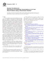
mounting is shown in Fig. 1, but other suitable devices may be
used. Mount a spherical bearing block between the upper end
of the cylinder and the moving head of the testing machine.
Center accurately both the hollow metal cylinder or other
device and the spherical bearing block so that the load will be
applied uniformly to the test specimen.
7.2.3 Measurement of Thickness—When the specimen has
been mounted as described in 7.2.2 and is subjected only to the
pressure of the dead weight of the 41⁄2 by 41⁄2 by 1⁄2-in. (114 by
114 by 13-mm) metal plate, determine its thickness by means
of the measuring device. When the load-transferring apparatus
and spherical bearing block are placed on the test specimen,
some compression may result. Consider this reduction in
thickness as part of the 50 % reduction in thickness to be
applied.
7.2.4 Recovery—For the determination of the percentage of
recovery, give the specimen a single application of a load
sufficient to compress it to 50 % of its thickness before test.
Apply the load without shock and at such a rate that the
specimen will be compressed approximately 0.05 in. (1.3
mm)/min. Record this applied load. Immediately release the
load after application and permit to recover 10 min, after which
measure the thickness. Remove the load-transferring apparatus
and spherical bearing block from the test specimen following
the load application. Calculate the percentage of recovery as
follows:
4.8 Metal Plate, 41⁄2 by 41⁄2 in. 6 0.1 in. (114 by 114 6 2.5
mm) with parallel faces machined from 1⁄2-in. (6.4-mm) steel
plate.
4.9 Compression Tester, either hydraulic- or screw-type
equipment with sufficient opening between upper- and lowerbearing surfaces to permit the use of verifying apparatus. The
load applied to the test specimen shall be indicated with an
accuracy of 61.0 %. The upper-bearing device shall be a
spherically seated, hardened metal block firmly attached at the
center of the upper head of the machine. The center of the
sphere shall lie at the center of the surface of the block in
contact with the specimen. The block shall be closely held in its
spherical seat, but free to tilt in any direction. Load shall be
applied without shock at 0.05 in. (1.3 mm) per min.
4.10 Extractor Apparatus, Soxhlet Extractor with thermostatically controlled heating element.
5. Sampling
5.1 One representative sample approximately 2 ft2/1000 ft2
of joint filler shall be obtained and properly packaged for safe
transporting to the testing agency.
5.2 For self-expanding cork joint filler, a minimum of five
41⁄2 by 41⁄2-in. (114 by 114-mm) square specimens properly
banded and plastic wrapped at point of manufacture shall be
submitted for testing.
6. Preparation of Test Specimens
6.1 For the joint fillers made of cork, sponge rubber,
bituminous cork, or fiber, cut five specimens 4 by 4 in. (102 by
102 mm). Each specimen shall be freshly and squarely cut
using a metal plate as a cutting template, as described in 4.7.
6.2 For self-expanding cork only, after boiling the specimens in water as described in 7.1.1, air dry in ambient air 24
h. Then cut specimens to the size described in 6.1.
6.3 Determine the thickness of each specimen to the nearest
0.001 in. (0.03 mm).
7. Procedures
7.1 Expansion in Boiling Water:
7.1.1 For self-expanding cork joint filler only, use five of the
test specimens supplied by the manufacture as described in 5.2.
Determine the thickness of each specimen to the nearest 0.001
in. (0.03 mm). Immerse the specimens in boiling water for 1 h;
remove and allow to cool to room temperature for 15 min.
Measure the final thickness of each specimen to the nearest
0.001 in. Calculate the expansion as follows:
Expansion, %, of original thickness 5
A
3 100
B
Recovery, % 5
t1
3 100
t
(2)
where:
t = thickness of the specimen before test, and
t 1 = thickness 10 min after completion of the application of
load.
(1)
7.2.4.1 Retest Provision—In case the specimen fails to
comply with requirements of the specification, test a specimen
in accordance with the following procedure. Give the test
specimen three applications of a load sufficient to compress it
to 50 % of its thickness before test. Apply the load without
shock and at such a rate that the specimen will be compressed
approximately 0.05 in. (1.3 mm)/min. After the first and second
where:
A = thickness in inches after boiling in water, and
B = thickness in inches before boiling in water.
7.1.2 Prepare the test specimens for testing as described in
6.2.
7.2 Recovery and Compression:
2
D545 − 14
1—Flat Metal Plate.
2—Specimen.
3—Metal Plate 41⁄2 by 41⁄2 by 1⁄2 in. (102 by 102 by 13 mm).
4—U-Shape Bridge.
5—Measuring Device.
6—Hollow Cylinder.
7—Spherical Bearing Block.
FIG. 1 Typical Mounting of the Specimen for Recovery and Compression Tests
applications, release the load immediately, and permit the
specimen to recover 30 min before the load is again applied.
After the third application, release the load immediately and
permit the specimen to recover 1 h; then measure the thickness
again. Remove the load-transferring apparatus and spherical
bearing block from the test specimen during recovery periods
between compressions and following the third application of
load. Acceptance shall be based on the results of these check
tests. Calculate the percentage of recovery as follows:
Recovery, % 5
t1
3 100
t
4.6. Cover the specimen with a 1⁄2 by 4 by 4-in. (13 by 102 by
102-mm) metal plate ground to have plane parallel faces, as
described in 4.7. Use a simple U-shaped bridge to support
above the center of the specimen a dial or other suitable
measuring device reading to 0.001 in. (0.03 mm). Place upon
the plate metal cylinder or other device for transferring the load
from the moving head of the testing machine around the
measuring apparatus to the plate covering the specimen.
7.3.3 Measurement of Thickness—When the specimen has
been mounted as described in 7.3.2 and is subjected only to the
pressure of the dead weight of the 1⁄2 by 4 by 4-in. (13 by 102
by 102-mm) metal plate, determine its thickness by means of
the measuring device. When the load-transferring apparatus
and spherical bearing block are placed on the test specimen,
some compression may result. Consider this reduction in
thickness as part of the 50 % reduction in thickness to be
applied.
7.3.4 Extrusion—For the determination of the amount of
extrusion, give the specimen one application of a load sufficient to compress it to 50 % of its thickness before test. Apply
the load without shock at such a rate that the specimen will be
compressed approximately 0.05 in. (1.3 mm)/min. Determine
the amount of extrusion in inches by measuring the maximum
movement of the free edge of the test specimen during the
50 % compression of the specimen. Measure the extrusion by
means of a dial micrometer or other suitable device reading to
0.001 in. (0.03 mm).
(3)
where:
t = thickness of the specimen before test, and
t 1 = thickness 1 h after completion of the third application
of load.
7.2.5 Compression—Calculate the unit pressure by dividing
the maximum load in lbf (N) as determined in 7.2.4 by the area,
16 in.2 (0.0104 m2), and record as the unit pressure in psi (kPa).
7.3 Extrusion:
7.3.1 Test Specimens—For this test, use one of the test
specimens prepared as described in 6.1 (or one of the selfexpanding cork specimens prepared in 6.2). In the case of cork,
sponge rubber, bituminous cork, and fiber expansion joint
fillers, make these tests on specimens of the materials as
received. If the cork filler fails to meet the requirements of the
specifications, make check tests on specimens that have been
immersed in water for 24 h and subsequently air-dried for 24 h.
Base acceptance on the results of these check tests.
7.3.2 Mounting—Place the test specimen in a suitable steel
mold so constructed as to confine the lateral movement of the
specimen under compression to one side only, as described in
7.4 Boiling in Hydrochloric Acid:
7.4.1 In the case of cork and self-expanding cork expansion
joint fillers only, use one of the test specimens prepared as
described in 6.1 (or one of the expanded specimens prepared as
described in 6.2). Immerse the specimen in hydrochloric acid
3
D545 − 14
(HCl, sp gr 1.19) and boil for 1 h. Examine the test specimen
for evidences of disintegration.
where:
W1 =
W
=
l
=
w
=
t
=
7.5 Asphalt Content:
7.5.1 From the test specimens prepared as described in 6.1,
cut narrow strips of sufficient length to pack the thimble of the
Soxhlet Extractor; approximately 45 g is sufficient. Oven dry
the strips at 220 6 5°F (104 6 3°C) to constant weight in an
open tared weighing dish, then cool in a desiccator. Weigh to
the nearest 0.01 g, and subtract tare to obtain initial oven dry
weight of specimen.
7.5.2 Transfer the test strips to the extraction thimble of
known oven dry weight. Extract the asphalt in the Soxhlet
Extractor using a suitable solvent (see Note 2) until the extract
is essentially clear (color of weak tea).
7.7 Density:
7.7.1 Using a specimen prepared as described in Section 6
and, after air drying, weigh to the nearest 0.1 g. For air dry
material the specimen shall come to constant weight and
moisture in a conditioning atmosphere described in Test
Methods D1037 for “wood based fiber and particle panel
materials,” 65 6 1 % RH at 68 6 6°F. Constant weight is
defined as no change greater than 1 % sample weight after 24
h.
7.7.2 For fiber joint only, oven dry the specimen at 220 6
5°F (104 6 3°C) for 2 h. After oven drying, cool the specimen
to room temperature in a covered desiccator and weigh to
nearest 0.1 g.
7.7.3 Calculate the density in lb/ft3, as follows:
NOTE 2—A “suitable solvent” is any solvent that effectively separates
the asphalt. Dichloromethane (methylene chloride) or N-Propyl-Bromide
are commonly recommended. The solvent used shall be included in the
report.
7.5.3 After extraction, allow excess solvent to drain from
the thimble before transferring to an open tared weighing dish
and oven dry at 220 6 5°F (104 6 3°C) for 1 h. Cool in a
desiccator, then weigh and subtract weighing dish and thimble
to obtain the oven dry weight of the extracted fiber.
7.5.4 Calculate the percentage asphalt content by weight on
an oven dry basis as follows:
W 12W
Asphalt, % 5
3 100
W1
Density 5
(4)
Density 5
where:
W =
l
=
w
=
t
=
(8)
weight, g,
length, in.,
width, in., and
thickness, in.
8.1 The precision of these test methods are based on an
interlaboratory study (ILS) of this standard conducted in 2007.
Results in this study were obtained from a total of six
laboratories, testing five different joint-filler materials. Every
“test result” reported represents an individual determination.
Each participating laboratory reported up to ten replicate test
results for each material. Except for the inability of every
participating laboratory to provide test results for all study
parameters, Practice E691 was followed for the design and
analysis of the data; the details are given in ASTM Research
Report No. D04-1027.3
8.1.1 Repeatability Limit (r)—Two test results obtained
within one laboratory shall be judged not equivalent if they
differ by more than the “r” value for that material; “r” is the
(5)
7.6.2 In the event that the metal template or the test
specimen or both does not measure to within the tolerances
established in 4.7, the length and width of the test specimen
must be measured to within 0.01 in. and percent water
absorption by volume calculated as follows:
W1 2 W
3 100
16.41 3 l 3 w 3 t
3.81 W
l 3w 3t
8. Precision and Bias
where:
W 1 = weight after immersion, g,
W
= weight before immersion, g, and
t
= thickness, in.
Absorption by Volume, % 5
(7)
7.7.4 In the event that the metal template or the test
specimen or both does not measure to within the tolerances
established in 4.7, the length and width of the specimen must
be measured to within 0.01 in. and density calculated in lb/ft3
as follows:
7.6 Water Absorption:
7.6.1 Using a test specimen prepared as described in 6.1, dry
the specimen in air, weigh to the nearest 0.1 g, and immerse in
water at a temperature of 65 to 75°F (18 to 25°C) in a
horizontal position supported from the bottom of the container
with 1 in. (25 mm) of water over the specimen for 24 h.
Remove the specimen from the water and remove the excess
surface water from all sides of the specimen with blotting paper
or a paper towel. Quickly weigh the specimen to the nearest 0.1
g. Calculate percent water absorption by volume as follows:
W1 2 W
3 100
262t
0.238 W
t
where:
W = weight, g, and
t
= thickness, in.
where:
W 1 = initial oven dry weight of test strips, and
W = oven dry weight of extracted fiber.
Absorption by Volume, % 5
weight after immersion, g,
weight before immersion, g,
length of specimen, in.,
width of specimen, in., and
thickness of specimen, in.
3
Supporting data have been filed at ASTM International Headquarters and may
be obtained by requesting Research Report RR:D04-1027.
(6)
4
D545 − 14
smaller frequency than the 95 % probability limit would imply.
The repeatability limit and the reproducibility limit should be
considered as general guides, and the associated probability of
95 % as only a rough indicator of what can be expected.
interval representing the critical difference between two test
results for the same material, obtained by the same operator
using the same equipment on the same day in the same
laboratory.
8.1.1.1 Repeatability limits are listed in Tables 1-7.
8.1.2 Reproducibility Limit (R)—Two test results shall be
judged not equivalent if they differ by more than the “R” value
for that material; “R” is the interval representing the critical
difference between two test results for the same material,
obtained by different operators using different equipment in
different laboratories.
8.1.2.1 Reproducibility limits are listed in Tables 1-7.
8.1.3 The above terms (repeatability limit and reproducibility limit) are used as specified in Practice E177.
8.1.4 Any judgment in accordance with statements 8.1.1
and 8.1.2 would normally have an approximate 95 % probability of being correct, however the precision statistics obtained in
this ILS must not be treated as exact mathematical quantities
which are applicable to all circumstances and uses. The limited
number of laboratories reporting results guarantees that there
will be times when differences greater than predicted by the
ILS results will arise, sometimes with considerably greater or
8.2 Bias—At the time of the study, there was no accepted
reference material suitable for determining the bias for these
test methods, therefore no statement on bias is being made.
8.3 The precision statement was determined through statistical examination of 328 results, from six laboratories, on five
materials. These five joint fillers were described as the following:
Filler A
Filler B
Filler C
Filler D
Filler E
Cork
Self-Expanding Cork
Sponge Rubber
Closed-Cell Polyolefin Foam
Preformed Expansion Joint, Bituminous Type
To judge the equivalency of two test results, it is recommended to choose the joint filler closest in characteristics to the
test filler.
9. Keywords
9.1 joint fillers; nonextruding; resilient types
TABLE 1 Expansion (%)
A
Joint Filler
¯ dA
Average s X
B
161.4
Repeatability Standard De- Reproducibility Standard
Deviation (SR)
viation (Sr)
12.9
43.5
The average of the laboratories’ calculated averages.
5
Repeatability Limit (r)
Reproducibility Limit (R)
36.0
121.9
D545 − 14
TABLE 2 Density (lbs/cu ft)
Joint Filler
C
D
E
A
s X¯ d A
Average
30.06
2.15
19.32
Repeatability Standard De- Reproducibility Standard
Deviation (SR)
viation (Sr)
0.77
7.02
0.02
0.14
0.47
1.29
Repeatability Limit (r)
Reproducibility Limit (R)
2.16
0.05
1.32
19.66
0.39
3.62
Repeatability Limit (r)
Reproducibility Limit (R)
40.0
69.8
50.5
3.0
65.9
130.8
539.3
187.2
15.3
178.6
Repeatability Limit (r)
Reproducibility Limit (R)
1.3
12.0
Repeatability Limit (r)
Reproducibility Limit (R)
1.3
9.2
Repeatability Limit (r)
Reproducibility Limit (R)
25.3
10.5
0.7
2.5
16.8
26.7
13.7
3.4
5.5
23.6
Repeatability Limit (r)
Reproducibility Limit (R)
0.024
0.232
0.071
0.027
0.031
0.062
0.232
0.133
0.055
0.041
The average of the laboratories’ calculated averages.
TABLE 3 Compression (psi)
Joint Filler
A
B
C
D
E
A
Average
s X¯ d A
212.4
225.1
96.6
17.0
327.8
Repeatability Standard De- Reproducibility Standard
Deviation (SR)
viation (Sr)
14.3
46.7
24.9
192.6
18.1
66.9
1.1
5.5
23.6
63.8
The average of the laboratories’ calculated averages.
TABLE 4 Water Absorption (%)
A
Joint Filler
¯ dA
Average s X
E
10.9
Repeatability Standard De- Reproducibility Standard
Deviation (SR)
viation (Sr)
0.4
4.3
The average of the laboratories’ calculated averages.
TABLE 5 Asphalt Content (%)
A
Joint Filler
¯ dA
Average s X
E
39.1
Repeatability Standard De- Reproducibility Standard
Deviation (SR)
viation (Sr)
0.5
3.3
The average of the laboratories’ calculated averages.
TABLE 6 Recovery (%)
A
Joint Filler
¯ dA
Average s X
A
B
C
D
E
89.4
91.7
98.3
96.6
84.4
Repeatability Standard De- Reproducibility Standard
Deviation (SR)
viation (Sr)
9.0
9.5
3.8
4.9
0.3
1.2
0.9
2.0
6.0
8.4
The average of the laboratories’ calculated averages.
TABLE 7 Extrusion (in.)
Joint Filler
A
B
C
D
E
A
¯d
Average s X
A
0.032
0.060
0.068
0.021
0.018
Repeatability Standard De- Reproducibility Standard
Deviation (SR)
viation (Sr)
0.009
0.022
0.083
0.083
0.025
0.048
0.009
0.019
0.011
0.015
The average of the laboratories’ calculated averages.
6
D545 − 14
ASTM International takes no position respecting the validity of any patent rights asserted in connection with any item mentioned
in this standard. Users of this standard are expressly advised that determination of the validity of any such patent rights, and the risk
of infringement of such rights, are entirely their own responsibility.
This standard is subject to revision at any time by the responsible technical committee and must be reviewed every five years and
if not revised, either reapproved or withdrawn. Your comments are invited either for revision of this standard or for additional standards
and should be addressed to ASTM International Headquarters. Your comments will receive careful consideration at a meeting of the
responsible technical committee, which you may attend. If you feel that your comments have not received a fair hearing you should
make your views known to the ASTM Committee on Standards, at the address shown below.
This standard is copyrighted by ASTM International, 100 Barr Harbor Drive, PO Box C700, West Conshohocken, PA 19428-2959,
United States. Individual reprints (single or multiple copies) of this standard may be obtained by contacting ASTM at the above
address or at 610-832-9585 (phone), 610-832-9555 (fax), or (e-mail); or through the ASTM website
(www.astm.org). Permission rights to photocopy the standard may also be secured from the Copyright Clearance Center, 222
Rosewood Drive, Danvers, MA 01923, Tel: (978) 646-2600; />
7