ZnO nanorods synthesis, characterization and applications 31034
Bạn đang xem bản rút gọn của tài liệu. Xem và tải ngay bản đầy đủ của tài liệu tại đây (1.83 MB, 33 trang )
1
ZnO Nanorods Arrays and Heterostructures for
the High Sensitive UV Photodetection
Soumen Dhara and P. K. Giri
Department of Physics, Indian Institute of Technology Guwahati, Guwahati,
India
1. Introduction
In the field of semiconductor nanostructures, one–dimensional (1D) ZnO nanostructures
(e.g. Nanowires, nanorods, nanobelts) are the most promising candidates due to their
important physical properties and application prospects. Large surface–to–volume ratio and
direct carrier conduction path of 1D ZnO nanostructures are the key factors for getting edge
over other types of nanostructures. ZnO is a direct wide band gap materials having bandgap
of ~3.37 eV and high excitonic binding energy, 60 meV at room temperature. 1D ZnO
nanostructures are extensively studied for their applications in various electronic and
optoelectronic devices, e.g., field effect transistors, ultra violet (UV) photodetectors, UV light
emitting diodes, UV nanolaser, field emitter, solar cells etc (Huang et al., 2001a; Liao et al.,
2007; Li et al., 2005; Kind et al., 2002; Soci et al., 2007; Alvi et al., 2010; Liu et al., 2009; Law et
al., 2005; Law et al., 2006; Yeong et al., 2007; Xu et al., 2010; Gargas et al., 2009) Various types
of ZnO nanorods (NRs) have been grown by several groups worldwide (Huang et al., 2001b;
Wei et al., 2010; Ahn et al., 2004; Li et al., 2008; Dhara & Giri, 2011c; Chen et al., 2010; Giri et
al., 2010) and they studied the effect of growth conditions on the morphology of the ZnO
NRs. The surface of the nanostructures has crucial role in determining the electrical and
optoelectronic properties of nano-devices. As the surface-to-volume ratio in NRs is very
high, the surface states also play a key role on optical absorption, luminescence,
photodetection and other properties. Thus, nanoscale electronic devices have the potential
to achieve higher sensitivity and faster response than the bulk material.
Since the first report on UV photodetection from single ZnO nanowires by Kind et al. (Kind
et al., 2002), many efforts have been made on 1D ZnO, including NRs to improve the
photodection and photoresponse behaviours. It is known that, photodetection and
photoresponse of the ZnO NRs depends on the surface condition, structural quality,
methods of synthesis and rate of oxygen adsorption and photodesorption. Therefore, it is
expected that arrays of NRs, surface modification or structural improvement can enhance
the photosensitivity as well as photoresponse. In the steps towards this goal, various groups
have put efforts to enhance the photoresponse and photosensitivity by using appropriate
dopant, structural improvement, surface passivation, peizo-phototronic effect and making
heterostructures with suitable organic or inorganic materials (Porter et al., 2005; Bera &
Basak, 2010; Dhara & Giri, 2011a; Liu et al., 2010a; Yang et al., 2010; Chang et al., 2011).
However, photosensitivity value and photoresponce time of the ZnO NWs based
www.intechopen.com
Nanorods
2
photodetectors will require significant improvements in order to meet future demands in
variety of fields. At the same time it is also more important to understand the origin of
improvement in the photodetection behaviours from ZnO NRs heterostructures in order to
play with the photodetection properties to make the flexible photodetectors.
In this chapter we will present a review of the recent achievements on the controlled growth
of vertically aligned ZnO NRs arrays and heterostructures by our group and other research
groups. Then we will describe the basic properties of these arrays for the application of UV
photodetection by means of crystal structures, optical absorption, emission, photoresponse,
photosensitivity and photocurrent spectra. The effects of arrays and heterostructures on the
mechanism of improved photodetection behavior are also discussed.
2. Growth of ZnO nanorods
ZnO is a II-VI group compound semiconductor whose ionic nature in between covalent and
ionic semiconductor. Although the crystal structures shared by ZnO are wurtzite, zinc
blende, and rocksalt, however at ambient conditions, only wurtzite phase is
thermodynamically stable. The wurtzite structure has a hexagonal unit cell with two lattice
parameters, a and c, in the ratio of c/a=1.633 and belongs to the space group of C
6
4
or P6
3
mc.
The hexagonal lattice of ZnO is characterized by two interconnecting sublattices of Zn
2+
and
O
2-
, such that each Zn ion is surrounded by a tetrahedral of O ions, and vice-versa. The Zn
terminated polar (0001) plane is the primary growth direction due to the lower surface
energy of this plane.
ZnO NRs with controlled shape and order could be grown by thermal vapor deposition
(TVD) (Huang et al., 2001b; Giri et al., 2010; Li et al., 2008; Yao et al., 2002), metal–organic
chemical vapor deposition (Yuan & Zhang, 2004; Park et al., 2002; Kim et al., 2009),
molecular beam epitaxy (Heo et al., 2002), hydrothermal/solvothermal methods (Breedon et
al., 2009; Verges et al., 1990; Alvi et al., 2010; Tak & Yong, 2005; Pacholski et al., 2002; Song &
Lim, 2007) and top down approach by etching (Wu et al., 2004). Among those techniques,
vapor deposition and chemical methods are the widely used techniques for their versatility
about controllability, repeatability, quality and mass production. MOCVD and MBE can
give high quality ZnO NRs arrays, but use of these techniques are limited, due to the poor
sample uniformity, low product yield, choices of substrate, and also the high experimental
cost. In the vapor deposition method, the growth process follows either vapor–liquid–Solid
(VLS) or vapor–solid (VS) mechanisms, depending on the growth conditions. On the other
hand, the NWs are grown by chemical reaction with the seed layer in the
hydrothermal/solvothermal methods with the assistance of cationic surfactant. In the
growth of ZnO NRs, in general metal catalyst or ZnO seed layer are used to promote the one
dimensional and vertical growth. In this case catalyst/seed layer act as a nucleation site and
facilitate the one–dimensional growth.
2.1 Mechanosynthesis method
Mechanosynthesis method is generally used for the synthesis of binary metal oxide or
complex oxide nanocrystals/quantum dots, however recently we successfully synthesized
good quality ZnO NRs with varying sizes. Metal nanoparticles (Tsuzuki & McCormick,
2004; Ding et al., 1995), ZnO nanocrystals (Tsuzuki & McCormick, 2001; Ao et al., 2006), CdS
www.intechopen.com
ZnO Nanorods Arrays and Heterostructures for the High Sensitive UV Photodetection
3
quantum dots (Patra et al., 2011) and various complex oxide nanoparticles (Pullar et al.,
2007; Mancheva et al., 2011) have been synthesized by several groups using
mechanosynthesis technique. For the growth of the NRs by this method, a suitable
surfactant should be chosen, which play a crucial role for the growth in one–direction. The
important advantages of this method are NRs can be grown at room temperature and a very
fast way, compared to any other chemical methods. In addition, size of NRs could be
controlled by reaction time duration and ball to mass ratio.
We have synthesized ZnO NRs of various diameters by mechanosynthesis method at room
temperature for reaction time as short as 30 minutes (Chakraborty et al., 2011; Dhara & Giri,
2011b). For the growth of ZnO NRs, mechanochemical reactions were carried out in a
planetary ball–milling apparatus. Zinc acetate [Zn(CH
3
COO)
2
], N-cetyl, N, N, N-Trimethyl
ammonium bromide (CTAB), a cationic surfactant and sodium hydroxide pellets were used
as starting materials. The cationic surfactant plays a crucial role in this reaction and facilitate
the growth along only one–direction. The reagents were first mixed together properly before
starting milling process. Millings were performed at 300 rpm for the time durations 30 min,
2 and 5 h. After the mechanosynthesis reaction, the resultant product was washed several
times by DI water and then with alcohol to remove the surfactant and other bi-products. In
the next step, it was dried for 2 h at 100° C to remove the water moister and organic agents.
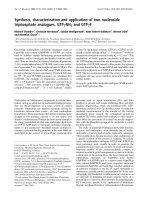
Figure 1 shows the field emission scanning electron microscope (FESEM) image of the ZnO
NRs grown for 30 min reaction, which clearly shows a bundle of dense ZnO NRs. The inset
shows the higher resolution isolated NRs of the same sample. The measured diameter and
length of the NRs varies in the range 22–45 nm and 300–780 nm, respectively. The FESEM
images of the ZnO NRs with reaction time 2 and 5h show similar morphology with smaller
lengths in the range 200–600 nm.
Fig. 1. FESEM image of the ZnO NRs grown for 30 min reaction, agglomerated bundle of
ZnO NRs are clearly visible. Inset shows the high resolution image of the isolated NRs.
www.intechopen.com
Nanorods
4
2.2 Vapor-liquid-solid growth method
Vapor–phase synthesis method is the most extensivly explored method for the growth of
one–dimensional nanostructructures. Among all vapor-based methods, the VLS mechanism
seems to be the most successful in generating large quantities of nanowires with single
crystalline structures. Wagner & Ellis (Wagner & Ellis, 1964) first reported this mechanism
in the 1960s to produce micrometer-sized wires, later justified thermodynamically and
kinetically by Givargizov in 1975 (Givargizov, 1975). In the early twenty–first century, this
mechanism is extensively explored by several research groups worldwide to prepare
nanowires and NRs from a rich variety of inorganic materials (Wu & Yang, 2000; Zhang et
al., 2001; Wu & Yang, 2001; Gudiksen & Lieber, 2000; Wu et al., 2002b; Duan & Lieber, 2000;
Pan et al., 2001; Gao et al., 2003; Chen et al., 2001; Wang et al., 2002b). The VLS growth
mechanism is practically demonstrated by Yang group (Wu & Yang, 2001) with the help of
in–situ transmission electron microscopy (TEM) techniques by monitoring the VLS growth
mechanism in real time. In a typical VLS growth, the growth species is evaporated first, and
then diffuses and dissolves into a liquid droplet (catalyst particle). The surface of the liquid
has a large accommodation coefficient, and is therefore a preferred site for deposition.
Saturated growth species in the liquid droplet will diffuse to and precipitate at the interface
between the substrate and the liquid. The precipitation will first follow nucleation and then
crystal growth. Continued precipitation or growth will separate the substrate and the liquid
droplet, resulting in the growth of nanowires/NRs. Preferential 1D growth continues in the
presence of reactant as long as the catalyst nanocluster remains in the liquid droplet state.
2.2.1 Self catalytic seed layer assisted growth
For VLS growth of the NWs, metal catalyst nanoisland/nanocluster is essential. However,
undesired metal contamination is generally seen for the NRs grown at relatively lower
temperature. For the binary compound, it is possible for one of these elements or the binary
compound itself to serve as the VLS catalyst. The nanostructures grown by this process is
named as self catalytic growth. The major advantage of a self-catalytic process is that it
avoids undesired contamination from foreign metal atoms typically used as VLS catalysts.
Different groups have reported the ZnO seed layer assisted catalyst free growth of ZnO NRs
and studied its morphology and crystallinity by different methods (Li et al., 2006; Li et al.,
2008; Li et al., 2009; Kim et al., 2009). Li et al. synthesized vertically aligned ZnO NRs with
uniform length and diameter on silicon substrate by vapor-phase transport method and
studied the structure, temperature dependent photoluminescence (PL) and field emission
behaviours. In this case ZnO seed layer was prepared by pulsed laser deposition (PLD)
technique. Kim et al. (Kim et al., 2009) obtained ZnO NRs by metal-organic chemical vapour
deposition method with enhanced aspect ratio at relatively a low temperature (300 °C) by
supplying additional Ar carrier gas at a high flow rates. In another work by Feng et al. (Feng
et al., 2010), well-crystalline with excellent optical properties, flower-like zinc oxide NRs
have been synthesized on Si(111) substrate using a PLD prepared Zn film as "self-catalyst"
by the simple thermal evaporation oxidation of the metallic zinc powder at 800 °C. The
crystalline quality of the ZnO seed layer strongly controlled the structural quality of the
NRs. In most of the cases, synthesized NRs were not aligned, hence have limited
applications in nanosize electronic and optoelectronic devices. The precise control over the
NRs/nanowires lengths and diameters using a self-catalytic VLS technique is very difficult.
www.intechopen.com
ZnO Nanorods Arrays and Heterostructures for the High Sensitive UV Photodetection
5
We have synthesized small diameter vertically grown ZnO NRs by self catalytic process
using ZnO seed layer. First, high quality thin ZnO seed layer of thickness of 200 nm was
deposited on the pre–cleaned, HF etched Si wafer by RF–magnetron sputtering. A mixture
of high purity ZnO powder and high purity graphite powder at a weight ratio of 1:1 was
used as a source. ZnO vapor was produced inside a horizontal quartz tube at 900°C, which
was placed inside the muffle furnace. The ZnO vapor was deposited on the seed layer
coated Si substrate in downstream direction at 800°C. The vapor deposition was carried out
under the Argon gas flow for 30 min. After deposition the entire system was cooled down to
room temperature and the synthesized product was characterized.
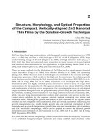
Figure 2 shows the ZnO seed layer assisted self catalytically grown ZnO NRs, which were
grown vertically on the Si substrate. The diameter of the NRs varies in the range of 100-200
nm with a length up-to 1µm. Although the ZnO NRs are grown vertically but the growth
orientation is random. From the FESEM image it is revealed that ZnO seed droplet is
present on the top of the NRs. It was reported that the quality and diameters of the ZnO
NRs depended on the crystallinity and particle size of the seed layer (Cui et al., 2005; Song &
Lim, 2007; Zhao et al., 2005). In our case, the grown NRs are non uniform in diameter and
length and also not well aligned due to the non uniform distribution of ZnO seed layer. As a
result, these ZnO NRs are not suitable for further use in nanodevices. Then we move to the
growth process of ZnO NRs by using a metal catalyst.
Fig. 2. 45° tilted FESEM image of the seed layer assisted self catalytically grown ZnO NRs.
2.2.2 Gold catalyst assisted growth
For the metal catalyst assisted growth of ZnO NRs, gold catalyst has got major popularity
and extensively used due to its comparatively lower eutectic temperature (temperature
require to form liquid droplet alloy of Au with the ZnO) and good solvent capability of
forming liquid alloy with ZnO. Huang et al. (Huang et al., 2001b) first reported on the
www.intechopen.com
Nanorods
6
synthesis of highly crystalline ZnO nanowires via VLS growth mechanism using mono–
dispersed Au colloid as catalyst. Diameter control of the nanowires was achieved by varying
the Au layer thickness. They were also able to synthesized patterned nanowires network by
patterning the Au catalyst on the substrate. Later, several groups have synthesized ZnO
NRs with varieties of ordering using Au catalyst. He at al. (He et al., 2006), using AFM
nanomachining technique together with catalytically activated vapor phase transport and
the condensation deposition process, have grown a variety of patterned and featured ZnO
NRs arrays. The grown pattern and feature are designed by the dotted catalyst prepared by
using AFM tip indentation with controlled location, density, and geometrical shape. The
vertical orientation of the NRs is achieved by the epitaxial growth on a single-crystal
substrate. This technique allows a control over the location, shape, orientation, and density
of the grown NRs arrays. Hejazi et al. (Hejazi & Hosseini, 2007) prepared Au-catalyzed ZnO
NRs and studied the growth rate on lateral size of NRs, concentration and supersaturation
of Zn atoms in the liquid droplet by a theoretical kinetic model, which is in good agreement
with the experimental results. A general expression for the NR growth rate was obtained by
materials’ balance in the liquid droplet and growth front. Based on the derived formula,
growth rate is inversely proportional to nanorod radius. A new understanding of the
vapour-liquid-solid process of Au catalyzed ZnO NRs was presented by Kirkham et al.
(Kirkham et al., 2007) by studying orientation relationships between the substrates, ZnO
NRs and Au particles using x-ray texture analysis. From analysis, they claimed that the Au
catalyst particles were solid during growth, and that growth proceeded by a surface
diffusion process, rather than a bulk diffusion process. ZnO NRs are also grown successfully
on the Si (100) or Al
2
O
3
substrates by using Cu or NiO or tin as catalyst (Li et al., 2003; Lyu
et al., 2002; Lyu et al., 2003; Wu et al., 2009; Gao et al., 2003).
ZnO NRs were synthesized by vapour deposition method on the Si substrate using Au as
catalyst. ZnO vapour was prepared at 900°C from the mixture of commercial ZnO powder
and graphite powder. ZnO NRs were grown at 800°C on the Au sputtered (of thickness ~5
nm) Si substrate.
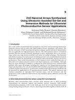
Figure 3 shows the SEM image of the randomly oriented vertically grown ZnO NRs. The
hexagonal facet of the ZnO NRs is clearly visible from the image. The diameters of the NRs
vary from 100 nm to few hundreds of nm with length about few microns. Although the as-
grown NRs are grown vertically but the diameter/length and orientation are not uniform. It
is suggested that the non-uniformity is due to the non–uniform grain size of the Au in the
sputtered film. It is also believed that lattice mismatch between Si and ZnO is responsible
for non–uniform orientation.
2.2.3 Combined seed layer and gold catalyst assisted growth
As discussed before, the seed layer as well as the Au catalyst both failed to produces well–
aligned ZnO NRs by vapor transport method. Zhao et al. (Zhao et al., 2005) first used the
ZnO buffer layer along with Au catalyst and a well–aligned ZnO NRs is obtained. We also
studied the effect of pre-depositing ZnO seed layer on the structure, morphology and
optical properties of Au catalytic grown vertically aligned ZnO NRs arrays at different
temperatures. (Giri et al., 2010) Based on the obtained results, it is understood that ZnO seed
layer and Au layer together acting as the nucleation site and guide the NRs growth. So, for
www.intechopen.com
ZnO Nanorods Arrays and Heterostructures for the High Sensitive UV Photodetection
7
the Au/ZnO/Si substrate the nucleation sites of ZnO NRs have the same orientation as ZnO
thin film by the effect of the seed layer. The catalyst layer transfers the orientation from seed
layer to NRs leading to a vertically well–aligned growth (Zhao et al., 2005; Giri et al., 2010).
Fig. 3. SEM image of Au catalyst assisted randomly oriented ZnO NRs grown at 800°C.
In the first step of ZnO NRs growth, a ZnO seed layer was deposited by RF-magnetron
sputtering followed by deposition of ultrathin Au layer by DC sputtering. Then ZnO NRs
were grown in the temperature range of 700-900°C by vapour transport method, as
described earlier.
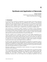
Figure 4 shows typical SEM morphology of ZnO NRs grown on Au/ZnO/Si substrate at
various growth temperatures. The NRs grew vertically on the substrate at 900°C, as seen
from Fig. 2(a). The sizes of the NRs are in the range of few hundred nanometers and non-
uniform diameters are due to variation in the local thickness of ZnO seed layer. ZnO seeds
act as a nucleation sites for the NRs growth and importantly offers very negligible lattice
mismatch or almost mismatch free interface between seed layer and NRs, which results in
the high quality vertically aligned growth of ZnO NRs arrays. NRs grown at 900 and 850°C
have larger diameter and highly aligned as comparable to the NRs grown at 700°C.
Fig. 4. SEM images of seeded layer and Au catalyst assisted grown aligned ZnO NRs grown
at different substrate temperatures: (a) 900°C, (b) 850°C, (c) 700°C, respectively.
www.intechopen.com
Nanorods
8
2.3 Aqueous chemical growth
Aqueous chemical growth methods are attractive for several reasons: low cost, less
hazardous, and thus capable of easy scaling up; growth occurs at a relatively low
temperature, compatible with flexible organic substrates; there is no need for the use of
metal catalysts; in addition, there are a variety of parameters that can tuned to effectively
control the morphologies and properties of the final products (Pearton et al., 2005; Xu et al.,
2009; Guo et al., 2011b). The growth process ensures that a majority of the NRs in the array
are in direct contact with the substrate and provide a continuous pathway for carrier
transport, an important feature for future electronic devices based on these materials.
Aqueous chemical methods have been demonstrated as a very powerful technique for the
growth of 1D ZnO nanostructures via selective capping mechanisms. It is believed that
molecular capping agents play a significant role in the kinetic control of the nanocrystal
growth by preferentially adsorbing to specific crystal faces, thus inhibiting growth of that
surface. Probably the most commonly used chemical agents in the existing literature for the
hydrothermal synthesis of ZnO NRs are Zn(NO
3
)
2
and hexamethylenetetramine (HMT)
(Boyle et al., 2002; Vayssieres, 2003; Tak & Yong, 2005; Song & Lim, 2007). In this case,
Zn(NO
3
)
2
provides Zn
2+
ions required for building up ZnO NRs. Using HMT as a structural
director, Greene et al. (Greene et al., 2006)produced dense arrays of ZnO NRs in aqueous
solution having controllable diameters of 30–100 nm and lengths of 2–5 m. With addition
of polyethylenimine (PEI) in the hydrothermal method, Qiu et al. able to synthesized well-
aligned ZnO NRs arrays with a long length of more than 40 m. However, without the
additive PEI, the length of the NRs was not more than 5 m. Guo et al. (Guo et al., 2011b)
studied the factors influencing the size, morphology and orientation of the epitaxial ZnO
NRs on the solution using hydrothermal method and discussed about tuning of the size and
morphology.
The role of HMT in aqueous chemical method is still not clearly understood. HMT is a
nonionic cyclic tertiary amine that can act as a Lewis base to metal ions and has been shown
to be a bidentate ligand capable of bridging two zinc(II) ions in solution. In this case, HMT
acts as a pH buffer by slowly decomposing to provide a gradual and controlled supply of
ammonia, which can form ammonium hydroxide as well as complex zinc(II) to form
Zn(NH
3
)
4
2+
(Greene et al., 2006). Because dehydration of the zinc hydroxide intermediates
controls the growth of ZnO, the slow release of hydroxide may have a profound effect on
the kinetics of the reaction. Additionally, ligands such as HMT and ammonia can kinetically
control species in solution by coordinating to zinc(II) and keeping the free zinc ion
concentration low. HMT and ammonia can also coordinate to the ZnO crystal, hindering the
growth of certain surfaces.
For the chemical growth of ZnO NRs, uniform distribution of ZnO nanocrystal seeds ware
prepared on the Si substrate by thermal decomposition of a zinc acetate precursor. Then
well–aligned ZnO NRs were synthesized by hydrolysis of zinc nitrate in water in the
presence of HMT at 90°C. 25 mM equimolar concentration of zinc nitrate and HMT was
used in the growth solution.
Figure 5 shows the well aligned ZnO NRs grown by aqueous chemical method with the help
of ZnO seed layer. A high density ZnO NRs grew vertically on the substrate over a large
area. The diameters of the NRs ranged from 30 to 40 nm and the length was about few
www.intechopen.com
ZnO Nanorods Arrays and Heterostructures for the High Sensitive UV Photodetection
9
microns. As a characteristic, hexagonal facet of the ZnO NRs are clearly seen from the top
view image.
Fig. 5. FESEM images of ZnO nanorods grown on ZnO/Si substrate: (a) top view and (b) 45°
tilted view.
3. Fabrication of ZnO nanorod heterostructures
It is considered that heterostructures are superior for the modulation of selective properties
of that material. Using suitable external materials for the heterostructures, one can modify
the properties of that material according to their requirements. In NRs structures, two types
of heterostructures could be fabricated either longitudinal or radial/axial with suitable
materials. Fabrication of planar semiconductor heterostructures for thin films is common,
whereas the synthesis of one-dimensional heterostructures is difficult. Axial
heterostructures, along the length of the NRs axis, have been reported for a few systems,
such as InAs/InP, GaAs/GaP and Si/SiGe nanowires (Bjo¨rk et al., 2002; Gudiksen et al.,
2002; Wu et al., 2002a). Recently there are reports on radial heterostructures of ZnO
nanowires/NRs using several organic/inorganic materials (Bera & Basak, 2009a; Liu et al.,
2010a; Bera & Basak, 2010; Liu et al., 2010b; Cheng et al., 2010a; Chang et al., 2011; Um et al.,
2011). Bera et al. studied the radial heterostructure effect with poly(vinyl alcohol) on the
photocarrier relaxation of the aqueous chemically grown ZnO nanowires. The photocurrent
(PC) decay time during steady ultraviolet illumination has been reduced in the
heterostructure, a decrease in the PC only by 12% of its maximum value under steady
illumination for 15 min and a decrease in the PC by 49% of its maximum value during the
same interval of time in the as-grown NWs. Three times enhancement in excitonic emission
has been obtained by Liu et al. from the polymethyl methacrylate based ZnO NWs
heterostructure. They explain this enhancement on the basis of surface states and energy
band theory, due to the decrease in nonradiative process by surface modification. When
ZnO NRs heterostructure was fabricated with another semiconducting material, ZnS, very
high and faster photoconductivity and also enhanced UV PL intensity are obtained.
ZnO NRs covered with dense and uniform ultra small metal nanoparticles (NPs) is another
form of heterostructures. Using suitable noble metal or low work function metal one could be
able to achieve very high intense UV PL with significant reduction in visible emission, which is
www.intechopen.com
Nanorods
10
one of the most important requirements for the application in UV LED or laser. Earlier, Lin et
al. (Lin et al., 2006) and later Cheng et al. (Cheng et al., 2010b) reported on the significant
enhancement of UV PL intensity and subsequent reduction in the defect related visible
emission from the ZnO NRs covered with ultra small Au NPs. It is also observed that, after
certain size of the Au NPs, the UV PL intensity start decreasing. They proposed that the
obtained enhancement is due to the defect loss along with the localized surface Plasmon
assisted recombination. Whereas when the NRs surface is covered with Ag NPs, a significant
improvement in the yellow–green light emission is obtained (Lin et al., 2011). Interestingly, it is
also observed that NRs covered with some metal gives rise to the decrement of the PL
intensity (Fang et al., 2011). Although a significant changes is obtained from the metal NPs
covered NRs, however a general mechanism for all types of metal covering is yet to emerge.
Here we fabricated ZnO NRs heterostructure by capping the surface with thin layer of
anthracene (Dhara & Giri, unpublished). Anthracene/ZnO NRs heterostructures was
fabricated by dip coating of the NRs in the diluted anthracene solution. We also fabricated
another two heterostructure systems one with decoration of Au NPs and other with Ti NPs
(Dhara & Giri, unpublished). From these heterostructures we investigated the origin of the
enhanced photoconduction and photoluminescence. Metal NPs decoration was done by
directly depositing NPs on the surface of the NRs by sputtering in a controlled way. For
systematic study we decorated the surface with different sizes of the NPs by varying the
sputtering time. Transmission electron microscope (TEM) image (Fig. 6) of the Au sputtered
ZnO NRs shows uniform distribution Au NPs with sizes 3-6 nm coated over the surface of
the NWs. The NRs grown by combined ZnO seed layer and Au catalyst using vapor
transport method is used for heterostructure fabrication. Due to the vertical alignment of the
NRs, Au NPs density is more at the top surface.
4. Structural and optical properties of the ZnO NRs
After the synthesis of nanostructures, it is essential to characterize the as-grown sample to
know the structure and related properties. Low–dimensional nanostructures, with possible
quantum–confinement effects and large surface area, show distinct mechanical, electronic
and optical properties, compared to the bulk materials counterpart. In this section, we will
summarise the structural characteristics of the ZnO NRs by x-ray diffraction (XRD), and
TEM imaging, followed by optical properties, in particular optical absorption and emission.
4.1 Structural characterization
The structural characterization of the mechanosynthesized NRs was done by XRD shows
(Fig. 7) characteristic peaks of pure hexagonal wurtzite phase of ZnO. It is observed that full
width at half maximum (FWHM) of the XRD peaks increase monotonically with increase in
reaction time. It is primarily due to the reduction of size of the NRs with increase in milling
time. With increasing reaction time, the size of NRs decreases and strain is induced during
the milling process, resulting in broadening of the XRD peaks.
Figure 8 (a) shows the low magnification TEM image of the 30 min reacted ZnO NRs.
Length and diameter of the NRs for ZNR-0.5h sample varies in the range of 300-800 nm and
25-40 nm, respectively. With increase in reaction time, both diameter and length of the ZnO
NRs are decreased due to mechanical milling process. During milling, the strain is
developed; however, for prolonged milling when the strain is high, the crystal breaks up
www.intechopen.com
ZnO Nanorods Arrays and Heterostructures for the High Sensitive UV Photodetection
11
and thus produces smaller sized NRs. After 5 h of milling, minimum diameter of ~15 nm is
obtained (Fig. 8(b)). Fig. 8(b) also shows the high resolution lattice image of the NR with
measured lattice spacing, 2.6 Å. The measured lattice spacing is in close agreement with the
(002) plane of hexagonal structure. The selected area electron diffraction patterns (not
shown) of the corresponding NR show the one–dimensional single–crystalline structures of
the as-grown NRs.
Fig. 6. TEM image of the Au NPs covered ZnO NRs, ultra small Au NPs on the surface of
ZnO NRs are shown by solid arrows.
Fig. 7. XRD patterns of the mechanosynthesized ZnO NRs with reaction time: (a) 30 min, (b)
2 h, and (c) 5 h.
www.intechopen.com
Nanorods
12
Fig. 8. TEM images of the mechanosynthesized ZnO NRs with reaction time; (a) 2 h, and (b)
high–resolution lattice image of the 5h sample.
Figure 9 shows the XRD patterns of the ZnO NRs grown on Au coated ZnO seed layer at
900, 850 and 700°C respectively. The observed patterns shows only one strong diffraction
peak indicates very high crystallinity. One strong (002) peak of hexagonal ZnO indicates the
c-axis orientation of the single crystalline ZnO NRs, which are well aligned and the growth
direction is perpendicular to the base surface. Relative intensities of the XRD peaks in Fig. 9
show that NRs grown at higher temperature have higher value of peak intensity, which
confirms higher crystallinity. From XRD analysis, we have found that Au coating on ZnO
seed layer induces a (111) orientation of the Au clusters at high temperature. Note that NRs
grown without the seed layer does not show any preferred orientation and possess inferior
crystallinity as compared to that grown with a seed layer. We have found that a substrate
temperature below 800°C is not favourable for the growth of aligned NRs by VLS method.
Fig. 9. XRD patterns of ZnO seed layer and Au catalyst assisted grown NRs array: grown at
substrate temperature (a) 900, (b) 850 and (c) 700°C, respectively
4.2 Optical properties
As the energy band structure and bandgap reflects on the optical properties of the
semiconductors, optical absorption spectroscopy is one of the important tool to probe the
www.intechopen.com
ZnO Nanorods Arrays and Heterostructures for the High Sensitive UV Photodetection
13
energy bandgap. UV-Vis absorption spectra of all the mechanosynthesis samples are shown
in Fig. 10. Observed peaks in the UV region correspond to the excitonic absorption of ZnO.
A clear blueshift in the absorption peak is observed from 369 nm to 365 nm, as the size
reduces from 40 nm to 15 nm. The observed blueshift is indicative of the increase in
bandgap with decrease in size of the NRs. This blueshift with size reduction cannot be
attributed fully to quantum size effect in ZnO NRs as these NRs have diameters in the range
15-40 nm, which is much higher than excitonic-Bohr diameter in ZnO (~6.48 nm). Therefore,
the change in bandgap is partly contributed by the strain induced band–widening. Rapid
thermal annealing (RTA) is an effective and simple tool to reduce the strain as well as to
improve structural quality. After RTA, a redshift in the excitonic absorption is observed
from all the samples, with respect to as-synthesized sample. This redshift is an indication of
the decrease in band gap energy as the result of recrystallization and strain relaxation of the
NRs (Chakraborty et al., 2011).
Fig. 10. UV–visible absorption spectra of (a) 5 h, (b) 2 h, and (c) 30 min mechanosynthesized
ZnO NRs. Effect of RTA at (d) 500°C and (e) 700°C on the 2 h samples.
The room temperature PL spectra of the mechanosynthesized NRs show three distinct peaks
(I-III) in the UV–blue region and one strong broad peak (IV) in the visible region. From 30
min to 5 h samples a blueshift in peak I is observed from 379 to 374 nm. This UV emission is
due to the bound excitonic recombination. The peak II at ~390 nm is likely to be due to
band-to-band transition between band tail states (Wang et al., 2002a). These band tail states
are primarily caused by the presence of defects at the surface of the NRs. The peak III at
www.intechopen.com
Nanorods
14
~409 nm is caused by the presence of zinc vacancy related defect states. The visible peak (IV)
at 582 nm is very broad and it is likely to be related to the atomic disorder at the surface of
the NRs caused by milling-induced lattice strain (Giri et al., 2007). An elegant review on
presence of various defects in ZnO and corresponding emissions is presented by McCluskey
et al. (McCluskey & Jokela, 2009). RTA-treated NRs show reduction in intensity of the peak
IV as a result of strain relaxation, whereas intensity of the other three peaks is significantly
enhanced. Interestingly, after RTA treatment, peaks II and III are shifted to higher
wavelengths. The lattice strain may change the position of the intermediate defect-related
states in the band structure of ZnO NRs. Recrystallization of NRs during RTA process is
responsible for the change in the band gap and corresponding redshift in the PL spectra.
Figure 12 is corresponding to the PL spectra of the as-grown NRs grown at 900, 850, 700°C,
respectively. VLS grown NRs shows two peaks in the PL spectra, one at UV region and
other one at green region. The first one is the near band edge (NBE) related excitonic
emission and latter one is the oxygen vacancy related defect emission, so called green
emission band. The intensity of the UV PL gradually increases with the decrease in growth
temperature. The lower intensity of NBE emission from vertically aligned NRs is primarily
due to the lower area of absorption by the tip of the aligned NRs and corresponding
emission. It is also possible that at higher temperature presence of oxygen vapour is
relatively low compared to the low temperature region, which results in the formation of
large no of oxygen vacancy states in the ZnO NRs. As a result strong green emission is
observed from the NRs grown at higher temperature
Fig. 11. PL spectra of 2 h mechanosynthesized ZnO NRs (a), after RTA at 500°C (b) and
700°C (c), respectively. Four peaks are fitted with Gaussian function (solid line) to the exp.
data (symbol).
www.intechopen.com
ZnO Nanorods Arrays and Heterostructures for the High Sensitive UV Photodetection
15
Fig. 12. PL spectra of combined seeded layer and Au catalyst grown aligned ZnO NRs at
various substrate temperatures: (a) 900°C, (b) 850°C, (c) 700°C.
5. Photodetection behaviours of the ZnO NRs
Electronic conductivity of the ZnO NRs significantly enhanced when it is exposed to the
light with wavelength below 380 nm. Using this property, ZnO NRs can be used for UV
photodetectors. The dramatic change of conductance between dark and UV exposure
suggest that the ZnO NRs photodetectors are also good candidates for optoelectronic
switches, with the dark state as OFF and the UV exposed state as ON. In the step
towards the efficient and faster photodetection from ZnO NRs/nanowires some important
works have been done recently, which are summarize in Table 1. Several types of
approaches have been reported e.g. structural improvement, efficient doping, and
heterostructures formation with suitable external materials. Zhou et al. (Zhou et al., 2009)
used nonsymmetrical Schottky-type (ST) contact devices and obtained higher sensitivity and
faster reset time. Pt microelectrode arrays were first fabricated on a SiO
2
/Si substrate by UV
lithography to make Schottky–type contact on one end of the nanowires and a focused-ion-
beam (FIB) deposited Pt-Ga electrode on other end of the ZnO nanowire for a good Ohmic
contact. He and coauthors utilized FIB technique to deposit Pt metal on ZnO nanowires to
effectively reduce the contact resistance, and thus achieved high photoconductive gain as
high as 10
8
. Chang et al. report the synthesis of a ZnO NR/graphene heterostructure by a
facile in situ solution growth method (Chang et al., 2011). By combining the attributes of
photosensitive ZnO NRs and highly conductive graphene, they are able to fabricate a highly
sensitive visible-blind ultra UV sensor. Recently, Park and coauthors obtained enhanced
photoresponse from isopropyl alcohol treated ZnO nanowire devices by introducing surface
roughness induced traps (Park et al., 2011). They propose that obtained enhancement is
attributed to an increase in adsorbed oxygen on roughening induced surface traps.
Therefore it is very important to have detail understanding about current conduction
mechanism and origin of enhancement from the heterostructures. It should be mentioned
that, till now, the lack of well-established fabrication method and standard procedures make
it difficult to compare the experimental results between different devices.
www.intechopen.com
Nanorods
16
Morphology Device
Type
Light of
Detection
(nm)
Bias
(V)
Maximum
Photosensitiv
ity
Photosensitivity
enhancement
factor from
unmodified
photodetector
Reference
Nanowire
Resistor 365 5 10
4
-10
6
– (Kind et al., 2002)
Nanorods
Resistor 325 2 19 – (Ahn et al., 2004)
Nanowires film
Resistor 254 5 17.7 – (Li et al., 2005)
Nanorod
FET 254 0.2 1000 – (Park et al., 2005)
Nanowire
Resistor 390 5 10
4
– (Soci et al., 2007)
Nanowires arrays
Resistor 325 3 18000 ~2.6 (Bera & Basak,
2009a)
Nanowires arrays
Resistor 360 3 10
4
~2.8 (Bera & Basak,
2009b)
Nanowire
Resistor 365 1 1500 ~4 (Zhou et al., 2009)
Nanowire
Resistor 254 4 1800 ~9.4 (Lin et al., 2009)
Nanowires arrays
Resistor 370 3 3367 `~5.2 (Bera & Basak,
2010)
Nanowires film
Resistor 365 8 – ~4.7 (Liu et al., 2010a)
Nanorods
Resistor 360 10 80 – (Manekkathodi et
al., 2010)
Nanowires arrays
Resistor 369 2.5 24200 ~5.4 (Dhara & Giri,
2011a)
Nanorod
Resistor 370 20 – ~3.0 (Chang et al., 2011)
Nanowires
n-i-n
junction
365 -5 1345 – (Kim et al., 2011a)
Nanorods
(interdigitated)
Resistor 379 5 12.1mA/W – (Guo et al., 2011a)
Nanowires arrays
Resistor 360 5 7600 ~2.2 (Bera & Basak,
2011)
Nanowire
FET 365 0.4 10
6
~1.8 (Park et al., 2011)
NWs network
Resistor 254 5 52 ~3 (Kim et al., 2011b)
Table 1. The performance characteristics of ZnO NRs/nanowires based photodetectors
reported in the literature.
5.1 Dark I–V characteristics
Recently we have shown that presences of native surface defects (oxygen vacancies) could
be identified from the dark I–V curves (Dhara & Giri, 2011a). The charge-depletion layer
induced by surface adsorption of oxygen molecules completely controls the charge transport
in NRs, if the diameter of the NRs is comparable to the depletion layer thickness. Another
important step in determination of the electrical properties of NRs is the metal–NRs
interface through metal electrode. In addition to the above factors, in case of nanowires
network structures, charge transport is also determined by the nanowire– nanowire
www.intechopen.com
ZnO Nanorods Arrays and Heterostructures for the High Sensitive UV Photodetection
17
contacts. The dark current-voltage (I-V) characteristic of the as-grown NRs shown in Fig. 13
shows a linear behavior up to a certain bias voltage. A linear fit to log-log plot of the I–V
data could give detailed information about the mechanism of current conduction process.
There is a crossover point of linear fitting around at 8V. Below this bias voltage, the power
dependence of current on voltage is exactly 1, indicating an Ohmic conduction region,
beyond which the current dependence on voltage is greater than one. This is most likely to
be space charge limited current (SCLC) (Rose, 1955; Ohkubo et al., 2008), which arise from
charge carriers trapped at the surface defect states that contribute to the current at higher
bias voltage. In case of SCLC, power dependence greater than two could be observed
depending on the energy distribution of trap centers. As the RTA treated NRs have very less
native defects due to structural improvement and release of built in stress, a linear curve is
expected. The NRs RTA treated at 800°C shows exactly a linear behavior, as expected.
Fig. 13. The dark current-voltage characteristics of as-grown and RTA-treated ZnO NWs
processed at 700°C and 800°C. Inset shows the magnified view of the selected region in log-
log scale.
5.2 Spectral dependence of photodetection
Wavelength dependent PC studies of the ZnO NRs shows that it gives very high PC when it
is exposed to the UV light (Fig. 14). The maximum PC is obtained at the excitation of 369 nm
light, which is the band gap wavelength of ZnO NRs. The observed strong peak at 369 nm in
the PC spectra is due to the band-edge absorption followed by generation of photocarriers
(electron-hole pair). The small hump–like peaks in the visible region are due to the
generation of carriers from the native defect states. In this case, the photosensitivity (photo-
to-dark current ratio) is ~4500, which is quite low. By structural improvement or
heterostructure formation, above hump could be eliminated and a visible–blind ZnO NRs
based photodetectors with high sensitivity could be made.
www.intechopen.com
Nanorods
18
Fig. 14. The photocurrent spectra of the ZnO NRs measured at 2.5 V bias.
5.3 Photoresponse
The photoresponse behaviour of the ZnO NRs measured under the excitation of 365 nm UV
light is shown in Fig. 15. It is seen that PC initially grows very fast and then slowly
increased with time and finally saturated (mechanism is explain in next sub-section). The
time-dependent PC growth and decay curves are fitted with the following equation (Dhara
& Giri, 2011a),
21
/
2
/
1
)1()(
ττ
tt
ph
eAeAItI
−−
−−+=
(1)
4
3
/
4
/
3
)()(
τ
τ
t
t
phph
eAeAItI
−
−
++∞=
(2)
where I, A
1
,
A
2
,
A
3
and A
4
are positive constants and I
ph
(∞) refers to the photocurrent after
infinitely long time of the decay experiment, which essentially is the dark current. The first
exponential term in the growth and decay equations corresponds to the electron-hole
generation and recombination processes and the last exponential term represents the oxygen
adsorption process. Calculated time constants from fittings are τ
1
= 25.7 s and τ
2
= 347.9 s for
PC growth, τ
3
=19.3 and τ
4
=316.0 s for PC decay, respectively. The photoresponse time for
the as-grown NRs is very slow due to the presence of intrinsic defects/trap centres.
5.4 Photodetection mechanism of ZnO NRs
It is known that, the photoresponse of the ZnO NRs consists of two parts: a rapid process of
photogeneration and recombination of electron–hole pairs, and a slow process of surface
adsorption and photodesorption of oxygen molecules (Dhara & Giri, 2011a). The oxygen
plays a crucial role in the photoresponse of ZnO. In dark condition, oxygen molecules from
the air are easily stuck on the NRs surface by adsorption process and trapped electrons
[O
2
(g)+e
−
→ O
2
−
] available on the surface near the Zn lattice and decreased the conductivity
(Kind et al., 2002), which is shown schematically in Fig. 16(a). This process leads to the
formation of depletion layer near the surface resulting in the band bending of the
conduction band (C.B) and the valence band (V.B). Formation of large number of ionized
www.intechopen.com
ZnO Nanorods Arrays and Heterostructures for the High Sensitive UV Photodetection
19
oxygen on the NWs surface enhances the band bending, resulting in a very low
conductivity. During the UV illumination, electron-hole pairs are generated [h→e
−
+h
+
] by
light absorption. Now these electrons/holes easily cross the depletion layers and contribute
to the photoconduction process. At the same time, holes take part in the oxidization of
ionized oxygen (O
2
-
+h
+
→O
2
(g), photodesorption process) and release one oxygen gas
molecule by electron–hole recombination process (Fig. 16(b)). Then few of the released
oxygen molecules are re-adsorbed on the surface and decrease the free electron carriers. The
energy band diagram during UV illumination is shown in (c). After certain time electron-
hole generation rate and oxygen re-adsorption rate becomes constant resulting in a steady
photocurrent. It is known that adsorption process is slower than the photodesorption
process. Therefore, during UV illumination, not all the holes are recombine with the
electrons present in the ionized oxygen. As a result, excess holes are available for
recombination with the exciton related free electrons. During photocurrent decay, the
exciton related electron–hole recombination dominates, which corresponds to the faster
decay component, so the photocurrent initially decreases very rapidly. With the surface re-
adsorption of oxygen, the photocurrent comes to the initial value very slowly.
Fig. 15. The Photocurrent growth and decay behaviors (photoresponse) of as-grown ZnO
NRs.
5.5 Effect of structural improvement
We have shown that a fivefold enhancement of photosensitivity in the UV region and faster
photoresponse could be obtained from the ZnO NWs/NRs by structural improvement
using RTA processing (Dhara & Giri, 2011a). The photocurrent growth and decay rates
(photoresponse) from RTA-treated NWs are improved by a factor of approximately 2. After
RTA at 800°C, the PC at 369 nm reaches a maximum value of 84.1 μA (Fig. 17) from that of
9.6 μA for the as-grown NWs, results in a sensitivity value of 24.2 × 10
3
, leading to an
enhancement factor of five. The PC growth and decay time constants are improved to 12.3
and 107.0 s for growth, 13.6 and 118.4 s for decay. The RTA processing substantially
www.intechopen.com
Nanorods
20
removes the surface defect-related trap centers and modified the surface of the ZnO NWs,
resulting in enhanced PC and faster photoresponse. During RTA processing, the NRs
recrystallize and structural quality is improved by releasing built-in stress and removing the
defect states. Due to reduction of surface defects, the PC in the visible region drastically
decreased. Therefore RTA processed photodetector is fully visible–blind and only sense the
UV light. The high photosensitivity even in low light intensity is an indication of very low
value of detection limit.
Fig. 16. A schematic of photoresponse mechanism of ZnO NRs: (a) at dark condition and (b)
during UV illumination. (c) Schematic energy band diagram of photoresponse process
during UV illumination.
Fig. 17. The photocurrent spectra of the ZnO NRs after RTA treated at 800°C.
5.6 Effect of heterostructure by surface capping
Here we present the effect of surface capping on the ZnO NRs with anthracene on the
enhancement of PC and photoresponse. Although the dark current is almost doubled after
www.intechopen.com
ZnO Nanorods Arrays and Heterostructures for the High Sensitive UV Photodetection
21
the capping, however a significant improvement in the photosensitivity is obtained.
Compared to the as-grown case, the photoresponse time becomes much faster for the
ZnO/anthracene system with response and reset times within second (Dhara & Giri,
unpublished). The reasons for choosing anthracene are that it can act as UV sensitive
material to enhance the photosensitivity and it can influence the oxygen adsorption process.
After anthracene capping the maximum photocurrent increases to 50 µA from 4 µA, which
is for as–grown NRs (Fig. 18). Photosensitivity value is also increased to 4183, leading to the
six–fold enhancement. Very high photosensitivity and low dark current are the basic
requirements for efficient photodetection. Due the surface capping, the surface of the NRs
becomes modified and in this case thickness of the depletion layer is much lower than the
case of as–grown NRs. When the sizes of the nanostructures are comparable to the space
charge layer, surface depletion greatly affects the density and the mobility of the carriers in
ZnO NWs rather than the contact potential (Li et al., 2007). Here anthracene layer is very
thin and the carriers easily tunnel through the layer to the electrodes, resulting in increment
in dark current.
The photoresponse spectrum (Fig. 19) measured at 360 nm shows very fast response with
response and reset times of 1.5 and 1.6 s, respectively (the response and reset time can be
defined as 1-1/e, (63%) of the maximum photocurrent increased and 1/e, (37%) of the
maximum photocurrent decreased, respectively). In contrast, the as-grown NRs have
response and reset time about 7.2 and 63.2 s, respectively. Therefore anthracene capped ZnO
NRs heterostructure has five times faster response time and about forty times faster reset
time, which is very good for real time application. Here, the anthracene has strong
absorption in the UV region, when it is excited with UV light the photoexcited charge
carriers transfer to the conduction band of ZnO NRs. This process results in high
photocurrent and consequent higher photosensitivity. Modification/reduction of surface
defects related traps by anthracene capping is also responsible for the obtained very high
photocurrent.
Fig. 18. Photocurrent spectra of the as-grown ZnO NRs and ZnO/anthracene based NRs
heterostructure.
www.intechopen.com
Nanorods
22
Fig. 19. Photoresponse behavior (at 360 nm) of the ZnO/anthracene based NRs
heterostructure in a repetitive UV light “ON” and “OFF” conditions.
5.7 Metal NPs decorated ZnO NRs heterostructures
In case of Au/ZnO heterostructures, Au NPs and ZnO NRs interface actively interplay on
the photodetection process. Au/ZnO heterostructure shows nearly linear dark I–V
characteristic with reduced dark current. The decrement of current is more prominent in the
lower bias voltage and at higher bias voltage it reached very close to the dark current of as-
grown NWs. It is known that when a metal is brought in contact with semiconductor, it
induces band bending due to the equilibrium of Fermi level (Liao et al., 2007; Dayeh et al.,
2007). Depending on the difference in the work–functions of metal and semiconductor, two
types of contacts have been formed at the metal semiconductor interface. Therefore, the
decrement in dark current is due to the large upward band bending and formation of
Schottky barrier at the interface between Au and ZnO. Because, Au has larger work–
function, 5.47 eV (Lide, 2009) than ZnO, 4.65 eV (Aguilar et al., 2009). As a result, no electron
will be transfer from Au to the conduction band of ZnO. However, at a lower bias voltage
few numbers of electrons can pass from ZnO to the Al electrode, giving very low dark
current. At higher bias voltage, which is greater than the Schottky barrier height, all the
electrons can flow to external circuit giving almost equal dark current as for the case of as-
grown NRs.
As expected, the as-grown NRs shows low PC in the UV region (Fig. 20.), whereas it is
significantly enhanced after Au NPs decoration. Here seven times enhancement in the
photosensitivity is obtained. The broad photocurrent peak from the Au/ZnO heterostructures
in the visible region is due to the Au NPs absorption related carrier transfer to the conduction
band of ZnO. As the dark current of the Au/ZnO heterostructures is lower than the as-grown
ZnO NRs, a lower PC is expected. However, the obtained PC is quite high. In this case, with
respect to the vacuum level, the energy level of oxygen vacancy defect states (5.43 eV) and
Fermi level of Au (5.47 eV) is very close to each other (Lide, 2009). Therefore, the electrons
from this defect states can transfer to the Fermi level of Au, which increases the electron
density at the Fermi level of Au. The Au NPs are excited by incident light in the UV-violet
www.intechopen.com
ZnO Nanorods Arrays and Heterostructures for the High Sensitive UV Photodetection
23
region due to interband transition and in the green region due to the surface Plasmon
resonance (SP band) (Garcia, 2011). After that the excited energetic electrons are stay in higher
energy states, and these are so active that they can escape from the surface of the NPs and can
transfer to the conduction band of ZnO. Under bias, these electrons along with electrons
generated by band edge absorption of ZnO contributed to the current conduction process.
Therefore, the obtained enhanced photocurrent in the UV as well as in the visible region is due
to the increase of electron density in the conduction band of ZnO by ZnO band edge
absorption and electron transport via Au NPs (Dhara & Giri, unpublished).
Fig. 20. Photocurrent spectra of the as–grown NRs and Au NPs decorated Au/ZnO NRs
heterostructures.
A faster photoresponse is obtained from the Au/ZnO heterostructures and it is almost
independent of the thickness of the Au layer. The response and reset times are as fast as 26.5
s and 70.0 s. In this case due to the decoration of Au NPs, surface of the ZnO NWs becomes
modified and facilitated to increase the adsorption and desorption process, resulting in
faster photoresponse.
On the contrary, Ti NPs decorated heterostructures show a linear I–V behavior with very
high dark current. The dark current gradually increases with increase in Ti coverage. Due to
the lower work–function of Ti (4.26 eV) (Lide, 2009) compared to ZnO, an Ohmic contact is
formed with downward band bending. In this case, more numbers of electrons can easily
transfer from Ti to the conduction band of ZnO at the interface. Then under the bias these
electrons contributes to the current conduction process results in high dark current.
The PC in the UV region is drastically enhanced at an excitation wavelength of 369 nm. The
Ti/ZnO heterostructure gives PC of 65.5 µA. Although the obtained PC from Ti/ZnO
heterostructure is very high, but due to higher dark current the photosensitivity values are
low. The photoresponse behaviours of the Ti decorated ZnO NRs show very fast response
with response and reset time within few seconds. The fastest response time of 5.5 s and reset
time of 7.7 s is obtained. These data indicate a significant improvement in the photoresponse
www.intechopen.com
Nanorods
24
process and much faster photoresponse could be obtained from Au or Ti decorated ZnO
NRs heterostructures.
Fig. 21. Photoresponse behaviours of the as-grown NRs and Au NPs decorated Au/ZnO
NRs heterostructures under the illumination of 365 nm UV light.
Fig. 22. Photoresponse behaviours of the as-grown NRs and Ti NPs decorated Ti/ZnO NRs
heterostructure under the illumination of 365 nm UV light.
www.intechopen.com
ZnO Nanorods Arrays and Heterostructures for the High Sensitive UV Photodetection
25
6. Summary
Here we reviewed our recent achievement on the controlled growth of vertically aligned
ZnO NRs arrays and their heterostructures for the applications of efficient UV
photodetection. We provided a summary of effects of several growth parameters on
different growth methods for the well aligned ZnO NRs arrays. ZnO NRs arrays grown by
three different methods; mechanosynthesis, vapour–liquid–solid and aqueous chemical
methods are presented here. It is shown that the combined effects of ZnO seed layer and Au
catalyst are favourable for the growth of well aligned ZnO NRs arrays. Three different types
of ZnO NRs based heterostructures were fabricated; one with surface capping of anthracene
and others with surface decoration of Au and Ti NPs with suitable sizes. Photodetection
behaviours of the different systems are studied by dark I–V characteristics, wavelength
dependent photocurrent and photoresponse. The results demonstrate that ZnO NRs
heterostructures are indeed excellent candidates for UV photodetectors with very high
sensitivity and faster response for real time sensing applications. Possible mechanisms of
improved photodetection behaviours from different systems are also presented. These
understanding will help to design and fabricate a ZnO NRs heterostructure based efficient
UV photodetectors. An up–to–date summary of important results by several research
groups worldwide on the ZnO NRs/NWs heterostructures based UV photodetectors is
presented in Table 1. Our approaches show comparable significant improvement over
several reports on ZnO NRs based photodetectors.
7. References
Aguilar, C. A.; Haight, R.; Mavrokefalos, A.; Korgel, B. A. & Chen, S. (2009). Probing
electronic properties of molecular engineered zinc oxide nanowires with
photoelectron spectroscopy. ACS. Nano, Vol.3, pp. 3057–3062
Ahn, S. E.; Lee, J. S.; Kim, H.; Kim, S.; Kang, B. K.; Kim, K. H. & Kim, G. T. (2004).
Photoresponse of sol-gel-synthesized ZnO nanorods. Appl. Phys. Lett., Vol.84, pp.
5022–5024
Alvi, N. H.; Riaz, M.; Tzamalis, G.; Nur, O. & Willander, M. (2010). Fabrication and
characterization of high-brightness light emitting diodes based on n-ZnO nanorods
grown by a low-temperature chemical method on p-4H-SiC and p-GaN. Semicond.
Sci. Technol., Vol.25, pp. 065004
Ao, W.; Li, J.; Yang, H.; Zeng, X. & Ma, X. (2006). Mechanochemical synthesis of zinc oxide
nanocrystalline. Powder Technol., Vol.168, pp. 148-151
Bera, A. & Basak, D. (2009a). Effect of surface capping with poly(vinyl alcohol) on the
photocarrier relaxation of ZnO nanowires. ACS Appl. Mater. Interface, Vol.1, pp.
2066–2070
Bera, A. & Basak, D. (2009b). Role of defects in the anomalous photoconductivity in ZnO
nanowires. Appl. Phys. Lett., Vol.94, pp. 163119
Bera, A. & Basak, D. (2010). Photoluminescence and Photoconductivity of ZnS-Coated ZnO
Nanowires. ACS. Appl. Mater. Interfaces, Vol.2, pp. 408–412
Bera, A. & Basak, D. (2011). Pd-nanoparticle-decorated ZnO nanowires: ultraviolet
photosensitivity and photoluminescence properties. Nanotechnol. , Vol.22, pp.
265501
www.intechopen.com