ZnO nanorods synthesis, characterization and applications 31037
Bạn đang xem bản rút gọn của tài liệu. Xem và tải ngay bản đầy đủ của tài liệu tại đây (581.37 KB, 19 trang )
4
Collective Plasmonic States Emerged
in Metallic Nanorod Array and Their Application
Masanobu Iwanaga
National Institute for Materials Science and
Japan Science and Technology Agency (JST), PRESTO
Japan
1. Introduction
Plasmons are well known as collective excitations of free electrons in solids. Simple unit
structures are nanoparticles such as spheres, triangles, and rods. Optical properties of
metallic nanoparticles were reported at the beginning of the 20th century (Maxwell-Garnett,
1904, 1906). Now it is well known that the resonances in metallic nanoparticles are described
by Mie theory (Born & Wolf, 1999). It is interesting to note that the studies on nanoparticles
were concentrated at the beginning of the century, at which quantum mechanics did not
exist. Shapes and dimensions of metallic nanoparticles such as triangles and rods were
clearly classified by their dark-field images after a century from the initial studies on
nanoparticles (Kuwata et al., 2003; Murray & Barnes, 2007). Nanoparticles were revived
around 2000 in the era of nanotechnology.
It may be first inferred that dimers and aggregations of metallic nanostructures have bonding
and anti-bonding states stemming from Mie resonances in the nanoparticles. The conjecture
was confirmed in many experimental studies (For example, Prodan et al., 2003; Liu et al., 2007;
Liu et al., 2009). Dimer structures composed of a pair of nanospheres or nanocylinders are one
of the most examined structures. At the initial stage of the dimer study, very high-
enhancement of electric field at the gap was frequently reported based on a computational
method of finite-difference time domain (FDTD), which is directly coded from classical
electromagnetics or Maxwell equations. However, recent computations including nonlocal
response of metal, which is quantum mechanical effect, disagree the very high-enhancement
(García de Abajo, 2008; McMahon et al., 2010). Especially, as the gap is less than 5 nm, the
discrepancies in cross section and extinction becomes prominent. While the physics in
dimensions of nm and less obeys quantum mechanics in principal, many experimental and
theoretical results show that classical electromagnetics holds quite well even in tens of nm
scale. Thus, it is not yet conclusive where the boundary of classical electromagnetics and
quantum mechanics exists in nm-scale plasmonics. It will be elucidated when further
development of nanofabrication techniques will be able to produce nm-precision metallic
structures with reliable reproducibility. Taking the present status of nanotechnology into
account, we focus on structures, such as gap, of the dimension more than 5 nm, where classical
electromagnetics holds well.
Contemporary nanofabrication technology can produce a wide variety of plasmonic
structures, which are usually made of metals. In addition to unit structures such as
www.intechopen.com
Nanorods
76
nanoparticles, periodic structures are also produced, where surface plasmon polaritons
(SPPs) are key resonances. Strictly, the SPPs in periodic structures are different from the
original SPPs induced at ideally flat metal-dielectric interface. Periodic structures enable to
reduce the original SPP into the first Brillouin zone; it is therefore reasonable to call the SPPs
in periodic structures reduced SPPs. The reduced SPPs were known since 1970s (Raether,
1988) and were revived as a type of resonances yielding extraordinary transmission in a
perforated metallic film (Ebbesen et al., 1998).
When producing periodic array of nanoparticles, what is expected? Periodic structures are
aggregation of monomers and dimers, and have photonic band structures. By structural
control, it is expected to obtain desired photonic bands, for example, wave-number-
independent, frequency-broad band, which is not obtained in dimers and so on. In terms of
photovoltaic applications, light absorbers working at a wide energy and incident-angle (or
wave-number) ranges are preferred. On the other hand, if one access highly enhanced
electromagnetic fields, states of high quality factor, which are associated with narrow band,
may be expected. Thus, the designs of plasmonic structures vary in accordance with needs.
Main purpose of this chapter is to show some of concrete designs of plasmonic structures
exhibiting collective oscillations of plasmons and broad-band plasmonic states, based on
realistic and precise computations.
This chapter consists of 7 sections. Computational methods are described in section 2. One-
dimensional (1D) and two-dimensional (2D) plasmonic structures are examined based on
numerical results in sections 3 and 4, respectively. As for applications, light absorption
management is examined in section 3 and polarization manipulators of subwavelength
thickness are shown in section 4. Conclusion is given in section 5.
2. Computational methods
Before describing the results of 1D and 2D plasmonic structures, computational methods are
noted in this section. In section 2.1, Fourier modal method or rigorously coupled-wave
approximation (RCWA) is described, suitable to compute linear optical spectra such as
reflection and transmission. In section 2.2, finite element method is explained, which is
employed to evaluate electromagnetic field distributions. Although the two methods have
been already established, the details in implementation are useful when researchers unfamiliar
to plasmonics launch numerical study. Furthermore, the detailed settings are described.
Realistic simulations are intended here. As material parameters, constructive equations in
Maxwell equations for homogeneous media have permittivity and permeability (Jackson,
1999). In the following computations, we took permittivity of metals from the literature
compiling measured data (Rakić et al., 1998). The permittivity of transparent dielectric was
set to be typical values: that of air is 1.00054 and that of SiO
2
is 2.1316. The permittivity of Si
was also taken from literature (Palik, 1991). At optical wavelengths, it is widely believed
that permeability is unity in solids (Landau et al., 1982); to date, any exception has not been
found in solid materials.
1
1
Metamaterials were initially intended to realize materials of arbitrary permittivity and permeability by
artificial subwavelength structures (Pendry & Smith, 2004). This strategy has been successful especially at
microwaves.
www.intechopen.com
Collective Plasmonic States Emerged in Metallic Nanorod Array and Their Application
77
2.1 Optical spectra
Linear optical responses from periodic structures are observed as reflection, transmission
and diffraction. To calculate the linear optical responses, it is suitable to transform
Maxwell equations into the Fourier representation. By conducting the transformation, the
equation to be solved is expressed in the frequency domain; therefore, optical spectra are
obtained in the computation with varying wavelength. In actual computations, it is crucial
to incorporate algorithm which realizes fast convergence of the Fourier expansion. If one
does not adopt it, Fourier expansion shows extremely slow convergence and practically
one cannot reach the answer. The algorithm could not be found for a few decades in spite
of many trials. The issue was finally resolved for 1D periodic systems in 1996 (Lalanne &
Morris, 1996; Li, 1996b; Granet & Guizal, 1996) and succeedingly for 2D periodic systems
in 1997 (Li, 1997). The Fourier-based method is often called RCWA. Commercial RCWA
packages are now available. In this study, we prepared the code by ourselves
incorporating the Fourier factorization rule (Li, 1997) and optimized it for the vector-
oriented supercomputers.
In general, the periodic structures are not single-layered but are composed of stacked layers.
Eigen modes in each layer expressed by Fourier-coefficient vectors are connected at the
interfaces by matrix multiplication. The intuitive expression results in to derive transfer
matrix (Markoš, 2008). Practically, transfer matrix method is not useful because it includes
exponentially growing factors. To eliminate the ill-behaviour, scattering matrix method is
employed. Transfer and scattering matrices are mathematically equivalent. In fact, scattering
matrix was derived from transfer matrix by recurrent formula (Ko & Inkson, 1988; Li,
1996a). The derivations were independently conceived for different aims: the former was to
solve electronic transport in quantum wells of semiconductors as an issue in quantum
mechanics (Ko & Inkson, 1988) and the latter was to calculate light propagation in periodic
media as an issue in classical electromagnetics (Li, 1996a).
In actual implementation, truncations of Fourier expansions are always inevitable as written
in equation (1), which shows Lth-order truncation. Of course, the Fourier expansion is exact
as L→∞.
,0,1,2,,
(,) exp( 2 / 2 / )
mn x
y
x
y
mn L
E x y E ik x ik y im d in d
ππ
=±± ±
=+++
(1)
In equation (1), 2D periodic structure of the periodicities of d
x
and d
y
is assumed and
incident wave vector has the components k
x
and k
y
. The term E
mn
is Fourier coefficient of
function E(x, y). For 2D periodic structures shown later, the truncation order is set to be L=
20. Then, estimated numerical fluctuations were about 1%. For 1D periodic structures, one
can assume that d
y
is infinity in equation (1); as a result, requirements in numerical
implementation become much less than 2D cases. It is therefore possible to set large order
such as L=200 and to suppress numerical fluctuations less than 0.5%.
Optical spectra calculated numerically by the Fourier modal method were compared with
measured spectra; good agreement was confirmed in stacked complementary 2D plasmonic
crystal slabs, which have elaborate depth profiles (Iwanaga, 2010b, 2010d).
www.intechopen.com
Nanorods
78
2.2 Electromagnetic-field distributions
Electromagnetic-field distributions were computed by employing finite element method
(COMSOL Multiphysics, version 4.2). One of the features is to be able to divide constituents
by grids of arbitrary dimensions.
To keep precision at a good level, transparent media were divided into the dimensions less
than 1/30 effective wavelength. As for metals, much finer grids are needed. Skin depth of
metals at optical wavelengths is a few tens of nm; therefore, grids of sides of a few nm or
less were set in this study. Such fine grids result in the increase in required memory in
implementation. Even for the unit domain in 2D periodic structures, which is minimum
domain and becomes three-dimensional (3D) as shown in Fig. 7, the allocated memory
easily exceeded 100 GB. As for 1D structures, the unit domain is 2D and requires much less
memory in implementation. Accordingly, computation time is much shorter; in case of Fig.
3, it took about ten seconds to complete the simulation.
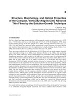
Fig. 1. Schematic drawing of an efficient 1D plasmonic light absorber of Ag nanorod array
on SiO
2
substrate, which was found based on the search using genetic algorithm. Plane of
incidence is set to be parallel to the xz plane.
The finite element method was applied for resolving the resonant states in the stacked
complementary 2D plasmonic crystal slabs and revealed the eigen modes successfully
(Iwanaga, 2010c, 2010d).
3. 1D periodic metallic nanorod array
Light absorbers of broad band both in energy and incident-angle ranges were numerically
found (Iwanaga, 2009) by employing simple genetic algorithm (Goldberg, 1989). One of the
efficient absorbers is a 1D metallic nanorod array as drawn in Fig. 1. The Ag nanorods (dark
grey) are assumed to be placed on the step-like structure of SiO
2
(pale blue). Periodic
direction was set to be parallel to the x axis, and the periodicity is 250 nm. The nanorods are
parallel to the y axis and infinitely long. The nanorods in the top layer have the xz rectangular
sections of 100×50 nm
2
. The other nanorods have the xz square sections of 50×50 nm
2
.
www.intechopen.com
Collective Plasmonic States Emerged in Metallic Nanorod Array and Their Application
79
In 1D structures, it was found that depth profiles are crucial to achieve desired optical
properties. Single-layered 1D structures have little degree of freedom to meet a designated
optical property whereas 1D structures of stacked three layers have enough potentials to
reach a given goal (Iwanaga, 2009).
In this section, we clarify the light-trapping mechanism by examining the optical and
absorption properties, and electromagnetic field distributions. Collective electrodynamics
between the nanorods plays a key role to realize the doubly broad-band absorber.
3.1 Optical responses and light absorption
Incident plane waves travel in the xz plane (that is, the wave vectors k
in
are in the xz plane) as
shown in Fig. 1, keeping the polarization to be p polarization, that is, incident electric-field
vector E
in
is in the xz plane. To excite plasmonic states in 1D periodic systems, the p
polarization is essential. If one illuminates the 1D object by using s-polarized light (that is, E
in
parallel to y), plasmonic states stemming from SPPs are not excited. Absorbance spectra under
p polarization at incident angles θ of -40, 0, and 40 degrees are shown in Fig. 2(a) with solid
line, dashed line, and crosses, respectively. The sign of incident angles θ is defined by the sign
of x-component k
in,x
(=|k
in
|sinθ) of incident wave vector. Absorbance A in % is defined by
0, 1, 2,
100 ( )
nn
n
ART
=±±
=− +
(2)
where R
n
and T
n
are nth-order reflective and transmissive diffractions, respectively. R
0
denotes reflectance and T
0
stands for transmittance. We computed linear optical responses
R
n
and T
n
by the Fourier modal method described in section 2.1, and evaluated A by use of
equation (2). The symbols R
0
and T
0
are respectively expressed simply as R and T from now
on. In the 1D structure in Fig. 1, since the periodicity is 250 nm, T
n
and R
n
for n ≠ 0 are zero
for θ = 0° in Fig. 2(a) and zero for θ = -40° at more than 525 nm.
In Fig. 2(a), absorption significantly increases at θ = -40° in the wavelength range longer
than 600 nm. It is to be stressed that absorption is more than 75% in a wide range from 600
to 1000 nm. Thus, the 1D structure in Fig. 1 works as a broad-band absorber in wavelengths
from the visible to near-infrared ranges.
Fig. 2. (a) Absorption spectra at -40° (solid line), 0° (dashed line), and 40° (crosses) under p
polarization. (b) Spectra of A (solid line), R (dotted line), and T (dashed line) at 620 nm
dependent on incident angles.
www.intechopen.com
Nanorods
80
In Fig. 2(b), The A spectrum at 620 nm dependent on incident angles is shown with solid
line. The corresponding T and R spectra are shown with blue dashed and red dotted lines,
respectively. Note that diffraction does not appear at this wavelength.
The T spectrum in Fig. 2(b) exhibits asymmetric distribution for incident angles θ, indicating
that the structure in Fig. 1 is optically deeply asymmetric. In contrast, the R spectrum is
symmetric for θ and the relation of R(θ)=R(-θ) is satisfied; the property is independent of
structural symmetry and is known as reciprocity (Potten, 2004; Iwanaga et al., 2007b). The A
spectrum takes more than 80% at a wide incident-angle range from 5° to -60°. It is thus
shown that the 1D periodic structure in Fig. 1 is a doubly broad-band light absorber.
3.2 Magnetic-field and power-flow distributions
To reveal the plasmonic state inducing the doubly broad-band absorption in Fig. 2, we
examine here the electromagnetic field distributions at 620 nm and θ = -40°, evaluated by the
finite element method. As described in section 3.1, incident plane waves are p-polarized and
induce transverse magnetic (TM) modes in the 1D periodic structure. Therefore, magnetic-
field distribution is suitable to examine the features of the plasmonic state.
In Fig. 3(a), magnetic-field distribution is presented; the magnetic field has only y
component under p polarization and the y-component of magnetic field is shown with
colour plot. Figure 3(a) shows a snapshot of the magnetic field, where the phase is defined
by setting incident electric field E
in
=(sin(-40°), 0, cos(-40°)) at the left-top corner position. The
propagation direction of incidence is indicated by arrows representing incident wave
vectors k
in
. To show a wide view at the oblique incidence, the domain in the computation
was set to include five unit cells. We assigned the yz boundaries (that is, the left and right
edges) periodic boundary condition.
The magnetic field distribution in Fig. 3(a) forms spatially oscillating pairs indicated by the
signs + and It is to be noted that the oscillating pairs are larger than each metallic nanorod
and are supported by three or four nanorods. The distributions are enhanced at the vicinity
of nanorod array and strongly suggest that collective oscillations take place, resulting in the
broad absorption band. As for plasmonic states, resonant oscillations inside metallic
nanorod have been observed in most cases, which are attributed to Mie-type resonances
(Born & Wolf, 1999). The present resonance is distinct from Mie resonances and has not been
found to our best knowledge.
In Fig. 3(b), time-averaged electromagnetic power-flow distribution is shown. The power
flow is equivalent to Poynting flux at each point. The z-component of the power flow is
shown with colour plot and the vectors of power flow are designated by arrows, which are
shown in the logarithmic scale for clarity. Oblique incidence is seen at the top of the panel
and the power flow successfully turns around the nanorods, going into SiO
2
substrate. In
addition to this finding, let us remind that the sum of R and T are at most 10% as shown in
Fig. 2(b), that the power flow in the substrate is not far-field component but mostly
evanescent components, and that most of incident power is consumed at the vicinity of the
nanorod array. Therefore, incident radiation is considered to be effectively trapped at the
vicinity of the nanorod array, especially in the substrate. Management of electromagnetic
power flow is a key to realize photovoltaic devices of high efficiency.
www.intechopen.com
Collective Plasmonic States Emerged in Metallic Nanorod Array and Their Application
81
Fig. 3. (a) A snapshot of y-component of magnetic field (colour plot). Incident wave vectors
are shown with arrows on the top. (b) Time-averaged electromagnetic power flow of z
component (colour plot). Vectors (arrows) are represented in the logarithmic scale.
3.3 Management of incident light for photovoltaic applications
As is shown in sections 3.1 and 3.2, periodic structure of metallic nanorod array can be
broad-band light absorber concerning both wavelengths and incident angles. Good light
absorbers are preferred to realize more efficient photovoltaic devices. Possibility for the
application is discussed here.
In considering producing efficient photovoltaic devices, it is crucial to exploit incident light
fully. In the context, perfect light absorbers are usually preferred. However, light absorption
and management of light have to be discriminated. If plasmonic absorbers consume incident
light by the resonances resident inside metallic nanostructures such as Mie resonance,
photovoltaic parts cannot use the incident light. Thus, it is not appropriate to optimize light
absorption by metallic nanostructures when one tries to incorporate them into photovoltaic
devices. Instead, one should manage to convert incident light to desired distributions by
metallic nanostructures (Catchpole & Polman, 2008a, 2008b). In Fig. 3(b), we have shown
that incident light effectively travels into substrate, in which photovoltaic parts will be
made. Additionally, most of the light taken in is converted to enhanced evanescent waves.
In comparison with the incident power, the power of the evanescent wave is more than a-
few-fold enhanced. Such local enhancement of electromagnetic fields is preferable in
photovoltaic applications.
As is widely known, management of incident light has been conducted in Si-based solar cells.
At the surface, textured structures are usually introduced to increase the take-in amount of
light (Bagnall & Boreland, 2008). The difference between the textured structures and the
designed metallic nanostructures exists in the enhancement mechanism; the former has no
enhancement while the latter can have local resonant enhancement as described above.
In actual fabrications of photovoltaic devices incorporating metallic nanostructures,
plasmonic structures will be made on semiconductors. The structure in Fig. 1 is made on
SiO
2
and has to be redesigned because the permittivity of SiO
2
and semiconductor such as Si
is quite different at the visible range. In this section, we have shown actual potentials of
plasmonic structures for light management through a concrete 1D periodic structure of
nanorod array. Since genetic algorithm search is robust and applicable to issues one wants
www.intechopen.com
Nanorods
82
to find solutions (Goldberg, 1989), we positively think of finding plasmonic structures for
photovoltaic applications.
In further search, 2D structures will be the targets, independent of incident polarizations. As
for the actual fabrications, one may think that the step-like structure as shown in Fig. 1 are
hard to produce by current top-down nanofabrication technique. In fact, there is hardly
report that 90° etching is successfully executed. However, there is enough room to improve
fabrication procedures; for example, if one could prepare hard mask and use calibrated
aligner to conduct dry etching of semiconductors, it would be possible to etch down at
almost 90° and even to produce step-like structures.
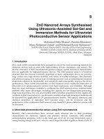
Fig. 4. Schematic drawing of 2D periodic Ag nanorod arrays on SiO
2
substrate. (a) Free
standing in air. (b) Embedded in a Si layer.
4. 2D periodic metallic nanorod array
2D periodic nanorod array has much variety in design. In this section, we show how
modification of unit cell drastically changes the optical properties. As concrete structures,
we present the results on the rectangular nanorod array as shown in Fig. 4 and refer to those
on circular nanorod array. In addition, it is shown that well-adjusted 2D nanorod arrays
work as efficient polarizers of subwavelength thickness. As the application, circular dichroic
devices are presented, which include 2D nanorod array as a component.
Before describing the numerical results on 2D metallic nanorod arrays, we mention how
they can be fabricated. It is probably easier to produce the structure in Fig. 4(b) than that in
Fig. 4(a). Since thin Si wafers can be fabricated in nm-precision as Si photonic crystal slabs
are made (Akahane et al., 2003), the procedure of electron-beam patterning, development,
metal deposition, and removal of resist results in the structure in Fig. 4(b) Free-standing
metallic nanorods seem to be relatively hard to produce. Simple procedure described as for
Fig. 4(b) is unlikely to be successful. Instead, other procedures have to be conceived. One of
the ways is to modify the fabrication procedure to produce metallic nanopillars of about 300
nm height (Kubo & Fujikawa, 2011).
4.1 Optical properties
In Fig. 5, T and R spectra of free-standing Ag nanorod arrays are shown. Unit cell structures
in the xy plane are drawn at the left-hand side. The periodicity is 250, 275, and 240 nm along
www.intechopen.com
Collective Plasmonic States Emerged in Metallic Nanorod Array and Their Application
83
both x and y axes in Figs. 5(a), 5(b), and 5(c), respectively. Grey denotes the xy section of Ag
nanorods, which is 50×50 nm
2
in the xy plane. The height of the nanorods was set to be 340
nm. The gaps between nanorods were set to be 0, 5, and 10 nm along the x and y axes in
Figs. 5(a), 5(b), and 5(c), respectively.
Fig. 5. Unit cell structures and the optical spectra of free-standing Ag nanorod array on SiO
2
substrate. Grey denotes Ag nanorod of 50×50 nm
2
in the xy plane. Gaps between each
nanorod are set along the x and y axes: (a) 0 nm, (b) 5 nm, and (c) 10 nm. Dimensions are
written in units of nm. T and R spectra at ψ = 45° are shown with solid and thin lines,
respectively. T and R spectra at ψ = 135° are represented with dashed and dotted lines,
respectively.
Incident plane waves illuminate the 2D structures at normal incidence. Incident polarization
E
in
was set to be linear, defined by azimuth angle ψ, that is, the angle between the x axis and
the E
in
vector, as drawn in Fig. 5(a). In accordance with the symmetry of the unit cell, two
polarizations ψ = 45° and 135° were probed. T and R spectra at ψ = 45° are displayed with
blue solid and red thin lines, respectively. T and R spectra at ψ = 135° are shown with blue
dashed and red dotted lines, respectively.
T spectra at ψ = 45° are sensitive to the gaps. In Fig. 5(a), at the visible range of wavelength
less than 800 nm, definite contrast of T at ψ = 45° and 135° is observed. As gaps becomes
larger, the contrast of T rapidly diminishes. Actually, in Fig. 5(c) where the gap is 10 nm, T
spectra at ψ = 45° and 135° become quite similar in spectral shapes and lose the difference
seen in Fig. 5(a). The gap dependence of T spectra implies that there exists resonant state in
www.intechopen.com
Nanorods
84
the structure of Fig. 5(a) at ψ = 45° and less than 800 nm and that the resonant state is lost by
the nm-order gaps between nanorods.
The strong contrast of T in Fig. 5(a) indicates that the 2D nanorod arrays serves as a good
polarizer of subwavelength thickness, which is employed in section 4.3.
Dimers or aggregations of rectangular and circular metallic nanostructures have attracted
great interest in terms of so-called gap plasmons in terms of enhanced Raman scattering
(Futamata et al., 2003; Kneipp, 2007). T spectra in Fig. 5 suggest that gap plasmons rapidly
disappear as the gap increases and are lost even with a small gap of 10 nm.
In Fig. 5, we show the results on rectangular Ag nanorod array; similar spectral
examinations were conducted for circular Ag nanorod arrays though the spectra are not
shown here. The qualitative tendency is similar and the contrast of T is rapidly lost as the
gaps between the circular nanorods increases in nm order.
In Fig. 6, we show T spectra of Ag nanorod arrays embedded in a Si layer of 340 nm height
along the z axis. Incident polarizations were ψ = 45° and 135°. T spectra at ψ = 45° and 135°
are shown with blue solid and blue dashed lines, respectively. It is first to be noted that T
spectra at ψ = 135° are almost independent of the gaps between Ag nanorods; T’s at the
wavelength range more than 1000 nm are several tens of % and exhibit Fabry-Perot-like
oscillations coming from the finite thickness of the periodic structure, suggesting that the 2D
structure for ψ = 135° is transparent due to off resonance. In contrast, T spectra at ψ = 45°
vary the shape significantly with changing the gaps and are very sensitive to the gaps. At
the 0 nm gap in Fig. 6(a), contrast of T is observed at the wavelength range longer than 1500
nm, indicating that the 2D structure in Fig. 4(b) also works as an efficient polarizer. The
states at 1770 nm (arrow in Fig. 6(a)) are examined by electric field distributions in Fig. 7.
4.2 Electromagnetic-field distributions on resonances
In Fig. 7, electric-field distributions are shown which correspond to the 2D periodic
structure of the unit cell in Fig. 6(a). Incident wavelength is 1770 nm; the wavelength is
indicated by an arrow in Fig. 6(a). Colour plots denote intensity of electric field |E| and
arrows stand for 3D electric-field vector. The unit domain used in the computations by the
finite element method is displayed. Periodic boundary conditions are assigned to the xz and
yz boundaries.
Figures 7(a) and 7(b) present the electric-field distributions at incident azimuth angle ψ =
45° and 135°, respectively. Incident plane wave travels from the left xy port to the right xy
port. The phase of incident wave at the input xy port was defined by E
in
= -(sin(45°),
cos(45°), 0) in Fig. 7(a) and by E
in
= (sin(135°), cos(135°), 0) in Fig. 7(b). The left panels show
3D view and the right panels shows the xy section indicated by cones in the left panels.
Electric-field distributions at ψ = 45° in Fig. 7(a) are prominently enhanced at the vicinity of
the connecting points of Ag nanorods. The enhanced fields are mostly induced outside the
Ag nanorods and oscillate in-phase (or coherently), suggesting that the resonant states are
not Mie type. On the other hand, electric-field distributions at ψ = 135° in Fig. 7(b) have local
hot spots at the corners of the Ag nanorods. It is usually observed at off resonant conditions.
The electromagnetic wave propagates dominantly in the Si part.
www.intechopen.com
Collective Plasmonic States Emerged in Metallic Nanorod Array and Their Application
85
Fig. 6. Unit cell structures and the T spectra of Ag nanorod array embedded in a Si layer on
SiO
2
substrate. Gaps of Ag nanorods along the x and y axes are (a) 0 nm, (b) 5 nm, (c) 10 nm,
and (d) 20 nm, respectively. Unit cells were set similarly to Fig. 5. T spectra at ψ = 45° and
135° are shown with solid and dashed lines, respectively.
Incident power was set to be 2.56×10
2
W/m
2
at the input xy port and the corresponding
electric-field intensity was 4.39×10
2
V/m. The resonant electric field at the vicinity of
nanorod array reaches 4.6×10
3
V/m at the maximum and shows about tenfold enhancement;
the scale bar has the maximum of 8.2×10
2
V/m and the distributions are displayed in a
saturated way to clearly present them near the connecting points. In air, incident and
reflected waves are superimposed in phase and consequently the electric-field intensity
takes larger values than the incident power.
4.3 Application for subwavelength circular dichroic devices
As shown in section 4.1, 2D periodic metallic nanorod arrays can serve as polarizers of
subwavelength thickness. In this section, we make use of such an efficient polarizer and
introduce subwavelength optical devices of circular dichroism.
www.intechopen.com
Nanorods
86
Fig. 7. Electric field distributions of the 2D periodic structure of the unit cell of Fig. 6(a): (a)
1770 nm and ψ = 45°; (b) 1770 nm and ψ = 135°. Left: 3D views of the unit domain. Right:
the xy sections, indicated by cones in the left panels.
Efficient polarizers selecting polarization vectors are one of the key elements to realize
various subwavelength optical devices. Another key element is wave plates which
manipulate the phase of electromagnetic waves. In Fig. 8(a), a concrete design of wave plate
of subwavelength thickness is presented, which is multilayer structure composed of Ag and
SiO
2
and made thin along the layers. Thickness of each Ag and SiO
2
layer along the x axis is
assumed to be 30 and 270 nm, respectively. Incident light sheds on the side or the xy plane.
Azimuth angle ψ is defined similarly to Fig. 5(a).
To clarify the basic optical properties of the multilayer structure, R spectra at ψ = 0° and 90°
under normal incidence are shown in Fig. 8(b). For simplicity, the thickness is assumed to be
sufficiently thick to eliminate interference pattern in R spectra. For ψ = 0° (that is, E
in
is
parallel to the x axis), the structure shows small R (red dashed line) and is transparent. For
ψ = 90° (that is, E
in
is parallel to the y axis), it shows R spectrum (red solid line) just as a
typical Drude metal (Ashcroft & Mermin, 1976). At longer wavelength range than 1000 nm,
the structure serves as wire-grid polarizer whereas, at shorter wavelength range than 1000
nm, the structure becomes transparent for any polarization and can work as an efficient
wave plate (Iwanaga, 2008).
www.intechopen.com
Collective Plasmonic States Emerged in Metallic Nanorod Array and Their Application
87
Fig. 8. Wave plate of subwavelength thickness. (a) Schematic drawing of structure and
optical configuration. (b) Reflectance spectra under normal incidence at ψ = 0° (dashed line)
and ψ = 90° (solid line).
The strong anisotropy of the multilayer structure is quantitatively expressed by using
effective refractive index (Iwanaga, 2007a); it was found that, as a wave plate, the x axis is
fast axis of effective refractive index of about 2 and the y axis is very slow axis of effective
refractive index less than 1. It is to be emphasized that such strong anisotropy has not been
found in solid material and makes it possible for the wave plates of multilayer structure to
be extremely thin. In artificial structures, working wavelength can be tuned at desired
wavelength by structural modifications; in contrast, it is very hard to change the working
wavelength in solid materials because resonance is intrinsic property of materials. The
feasibility in tuning is another advantage in subwavelength artificial structures.
Once key elements are found, the combinations are naturally derived and usually realized
by producing stacked structures. A recent example is orthogonal polarization rotator of
subwavelength thickness, which was numerically substantiated by designing a skew
stacked structure of wave plates (Iwanaga, 2010a). By introducing stacked structures,
potentials of subwavelength optical devices are greatly extended.
Figure 9(a) shows a concrete design of circular dichroic device (named I), which transforms
incident circular polarization to transmitted linear polarization. The circular dichroic device
has stacked structure of a wave plate of multilayer structure and a polarizer of 2D Ag
nanorod array. The wave plate basically plays a role as a quarter wave plate at the
wavelength range of the present interest. Each unit cell of the stacked layers is drawn in
detail at the bottom; the dimensions are written in units of nm. Grey denotes Ag and pale
blue SiO
2
. The thickness of the wave plate and the polarizer was set to be 284 and 210 nm,
respectively; therefore, the total thickness of the circular dichroic device was 494 nm.
In Fig. 9(b), T spectra under right-handed circular (RHC) and left-handed circular (LHC)
polarizations are shown with blue solid and blue dashed lines, respectively. Obviously,
definite contrast of T appears at about 850 nm. The degree of circular dichroism σ is defined
by the following equation.
RHC LHC
RHC LHC
TT
TT
σ
−
=
+
(3)
www.intechopen.com
Nanorods
88
When σ = 1, the optical device is optimized for RHC and when σ = -1, it is done for LHC. In
Fig. 9(c), the σ is shown and takes the value almost equal to unity at 855 nm, which is
indicated by a red arrow in Fig. 9(b). Since the thickness of the device is 494 nm, it is
confirmed that the circular dichroic device I is certainly subwavelength thickness, which is
58% length for the working wavelength.
Fig. 9. Circular dichroic device I of subwavelength thickness. (a) Stacked subwavelength
structure transforming circular into linear polarizations. (b) Transmittance spectra under
RHC (solid line) and LHC (dashed line). (c) Degree of circular polarization σ, defined by
equation (3). (d) Polarization of transmitted light.
Figure 9(d) presents polarization of transmitted light (red closed circles). Electric field was
recorded for one wavelength and projected onto the xy plane. Clearly, the transmitted light
is linearly polarized, characterised as ψ = 45° by using azimuth angle ψ.
Figure 10(a) shows schematic drawing of circular dichroic device II, transforming incident
circular polarization into counter-circular polarization. The device is composed of stacked
structure of wave plate, polarizer, and wave plate and has subwavelength thickness for the
working wavelength. Each unit cell of the components is drawn at the bottom and is
specified; the first layer means that incident plane waves illuminate first, and succeedingly
the incident waves travel through the second and third layers. Grey denotes Ag and pale
blue SiO
2
. The thickness of the first, second, and third layers is 284, 210, and 255 nm,
respectively; the total thickness is 749 nm. Although the basic design of the circular dichroic
device I is similar to the device II in Fig. 9, the thickness of the third layer was finely
adjusted to obtain ideally circular polarization of transmitted light because evanescent
components contribute at the interface of the second and third layers, and modify the
electrodynamics in the device II from that at homogeneous interface by plane waves.
Figure 10(b) shows T spectra under RHC (blue solid line) and LHC (blue dashed line)
incidence. Definite contrast of T is observed at 820-900 nm; T under LHC incidence is well
www.intechopen.com
Collective Plasmonic States Emerged in Metallic Nanorod Array and Their Application
89
suppressed. In Fig. 10(c), the degree of circular dichroism σ is shown, evaluated by equation
(3). Almost ideal circular dichroism is realized at 855 nm, indicated by a red arrow in Fig.
10(b).
Fig. 10. Circular dichroic device II of subwavelength thickness. (a) Stacked subwavelength
structure transforming circular into counter-circular polarizations. (b) Transmittance spectra
under RHC (solid line) and LHC (dashed line). (c) Degree of circular polarization σ, defined
by equation (3). (d) 3D plot of the trajectory of polarization of transmitted light with wave
vector k
t
; the wavelength is 855 nm and indicated by an arrow in (b).
Figure 10(d) presents 3D plot of trajectory of the transmitted polarization (or electric field) at
855 nm. The polarization circularly rotates in the left-handed direction along the transmitted
wave vector k
t
. Thus, it is shown that a unique circular dichroic device transforming
incident circular polarization into the counter-circular polarization can be realized with
subwavelength thickness by employing metallic nanostructures such as thin line and
nanorods. Miniature optical devices shown in this section can serve as key elements in
micro-optics circuits in the future.
In considering circular dichroism, it is often preferred to use helical structures. Probably,
helical structures are connected unconsciously in mind to helical distributions of
polarization such as Fig. 10(d), that is, circular polarizations. In principal, circular dichroism
originates from simultaneous manipulations of polarization vector and the phase as proved
in Figs. 9 and 10.
Resonances inducing simultaneous change of polarization vector and phase are possibly to
be resident in helical structures; an example is periodic array of gold helical structures
which serves as a circular dichroic device in infrared range (Gansel et al., 2009). Note that it
is impossible to move the working wavelength to the visible range by simply making the
smaller structures because scaling law does not hold in the periodic structures including
metals which have wavelength-dependent permittivity.
To find new structures serving as circular dichroic devices, nature can provide clues.
Jewelled beetles are rather widely known as circular dichroic insects. It turned out that the
wings have helically stacked structures (Sharma et al., 2009). Biomimetics thus reminds us to
learn from nature.
www.intechopen.com
Nanorods
90
5. Conclusion
Periodic metallic nanorod arrays have been investigated based on the numerical methods. It
was shown that the nanorod arrays have collective resonant states or coherent oscillations
outside each nanorod; the field distributions suggest that the resonant states are distinct
from Mie resonance. The resonant states form broad band in wavelength, indicating that
they are continuum. In the 1D periodic structure of stacked layers, the resonant states are
also broad band in incident angles. The doubly broad-band features have not been reported
in metallic nanostructures. It was also shown in 2D structures of nanorod array that the
structures are crucial to realize the broad-band plasmonic states and that geometrical
modifications in the order of 5 nm significantly affect the collective states. Further
development of nanofabrications will lead us to the novel plasmonic states. In terms of
applications, the 1D nanorod array was discussed as a light managing element for
photovoltaic devices and the 2D nanorod arrays were incorporated in highly efficient
subwavelength circular-dichroic devices which were concretely designed to work at optical
wavelengths, transforming incident circular polarizations to desired polarizations.
6. Acknowledgment
This study was partially supported by Cyberscience Centre, Tohoku University, by JST,
PRESTO, and by JSPS KAKENHI (Grant No. 22760047).
7. References
Akahane, Y., Asano, T., Song, B S., & Noda, S. (2003). High-Q photonic nanocavity in a two-
dimensional photonic crystal. Nature, Vol. 425, No. 6961, (October 2003), pp. 944-
947, ISSN 0028-0836
Ashcroft, N. W. & Mermin, N. D. (1976). Solid State Physics (International ed.), Saunders
College Publishing, ISBN 0-03-049346-3, Orlando, United States of America
Bagnall, D. M. &, Boreland, M. (2008). Photovotaic technologies. Energy Policy, Vol. 36, No.
12, (December 2008), pp. 4390-4396, ISSN 0301-4215
Born, M. & Wolf, E. (1999). Principals of Optics (seventh extended ed.), Cambridge Univ.
Press, ISBN 0-521-642221, Cambridge, United Kingdom
Catchpole, K. R. & Polman, A. (2008a). Design principles for particle plasmon enhanced
solar cells. Applied Physics Letters, Vol. 93, No. 19, (November 2008), pp. 191113-1—
191113-3, ISSN 0003-6951
Catchpole, K. R. & Polman, A. (2008b). Plasmonic solar cells. Optics Express, Vol. 16, No. 26,
(December 2008), pp. 21793-21800, ISSN 1094-4087
Ebbesen, T. W., Lezec, H. J., Ghaemi, H. F., Thio, T., & Wolff, P. A. (1998). Extraordinary
optical transmission through sub-wavelength hole arrays. Nature, Vol. 391, No.
6668, (February 1998), pp. 667-669
Futamata, M., Maruyama, Y., & Ishikawa, M. (2003). Local Electric Field and Scattering
Cross Section of Ag Nanoparticles under Surface Plasmon Resonance by Finite
Difference Time Domain Method. The Journal of Physical Chemistry B, Vol. 107, No.
31, (August 2003), pp. 7607-7617, ISSN 1520-6106
Gansel, J. K., Thiel, M., Rill, M. S., Decker M., Bade, K., Saile, V., von Freymann, G., Linden,
S., & Wegener, M. (2009). Gold Helix Photonic Metamaterial as Broadband Circular
www.intechopen.com
Collective Plasmonic States Emerged in Metallic Nanorod Array and Their Application
91
Polarizer. Science, Vol. 325, No. 5947, (September 2009), pp. 1513-1515, ISSN 0036-
8075
García de Abajo, F. J. (2008). Nonlocal Effects in the Plasmons of Strongly Interacting
Nanoparticles, Dimers, and Waveguides. The Journal of Physical Chemistry C, Vol.
112, No. 46, (October 2008), pp. 17983-17987, ISSN 1932-7447
Goldberg, D. E. (1989). Genetic Algorithms in Search, Optimization & Machine Learning,
Addison-Wesley, ISBN 0-201-15767-5, Boston, United States of America
Granet, G. & Guizal, B. (1996). Efficient implementation of the coupled-wave method for
metallic lamellar gratings in TM polarization. Journal of the Optical Society of America
A, Vol. 13, No. 5, (May 1996), pp. 1019-1023, ISSN 0740-3232
Iwanaga, M. (2007a). Effective optical constants in stratified metal-dielectric metamaterial.
Optics Letters, Vol. 32, No. 10, (May 2007), pp. 1314-1316, ISSN 0146-9592
Iwanaga, M., Vengurlekar, A. S., Hatano, T., & Ishihara, T. (2007b). Reciprocal
transmittances and reflectances: An elementary proof. American Journal of Physics,
Vol. 75, No. 10, (October 2007), pp. 899-902, ISSN 0002-9505
Iwanaga, M. (2008). Ultracompact waveplates: Approach from metamaterials. Applied
Physics Letters, Vol. 92, No. 15, (April 2008), pp. 153102-1—153102-3
Iwanaga, M. (2009). Optically deep asymmetric one-dimensional plasmonic crystal slabs:
Genetic algorithm approach. Journal of the Optical Society of America B, Vol. 26, No. 5,
(May 2009), pp. 1111-1118, ISSN 0740-3224
Iwanaga, M. (2010a). Subwavelength orthogonal polarization rotator. Optics Letters, Vol. 35,
No. 2, (January 2010), pp. 109-111
Iwanaga, M. (2010b). Polarization-selective transmission in stacked two-dimensional
complementary plasmonic crystal slabs. Applied Physics Letters, Vol. 96, No. 8,
(February 2010), pp. 083106-1—083106-3
Iwanaga, M. (2010c). Subwavelength electromagnetic dynamics in stacked complementary
plasmonic crystal slabs. Optics Express, Vol. 18, No. 15, (July 2010), pp. 15389-15398
Iwanaga, M. (2010d). Electromagnetic eigenmodes in a stacked complementary plasmonic
crystal slab. Physical Review B, Vol. 82, No. 15, (October 2010), pp. 155402-1—
155402-8, ISSN 1098-0121
Jackson, J. D. (1999). Classical Electrodynamics (third ed.), Wiley, ISBN 0-471-30932-X,
Hoboken, United States of America
Kneipp, K. (2007). Surface-enhanced Raman scattering. Physics Today, Vol. 60, No. 11,
(November 2007), pp. 40-46, ISSN 0031-9228
Ko, D. Y. K. & Inkson, J. C. (1988). Matrix method for tunneling in heterostructures:
Resonant tunneling multilayer systems. Physical Review B, Vol. 38, No. 14,
(November 1988), pp. 9945-9951
Kubo, W. & Fujikawa, S. (2011) Au Double Nanopollars with Nanogap for Plasmonic
Sensor. Nano Letters, Vol. 11, No. 1, (January 2011), pp. 8-15, ISSN 1530-6984
Kuwata, H., Tamaru, H., Esumi, K., & Miyano, K. (2003). Resonant light scattering from
metal nanoparticles: Practical analysis beyond Rayleigh approximation. Applied
Physics Letters, Vol. 83, No. 22, (December 2003), pp. 4625-4627
Lalanne, P. & Morris, G. M. (1996). Highly improved convergence of the coupled-wave
method for TM polarization. Journal of the Optical Society of America A, Vol. 13, No.
4, (April 1996), pp. 779-784
www.intechopen.com
Nanorods
92
Landau, L. D., Lifshitz, E. M., & Pitaevskii, L. P. (1982). Electrodynamics of Continuous Media
(second ed. revised and extended), Elsevier, ISBN 0-7506-2634-8, Oxford, United
Kingdom
Li, L. (1996a). Formulation and comparison of two recursive matrix algorithm for modelling
layered diffraction gratings. Journal of the Optical Society of America A, Vol. 13, No. 5,
(May 1996), pp. 1024-1035
Li, L. (1996b). Use of Fourier series in the analysis of discontinuous periodic structures.
Journal of the Optical Society of America A, Vol. 13, No. 9, (September 1996), pp. 1870-
1876
Li, L. (1997). New formulation of the Fourier modal method for cross surface-relief gratings.
Journal of the Optical Society of America A, Vol. 14, No. 10, (October 1997), pp. 2758-2767
Liu, N., Guo, H., Fu, L., Kaiser, S., Schwerizer, H., & Giessen, H. (2007). Plasmon
Hybridization in Stacked Cut-Wire Metamaterials. Advanced Materials, Vol. 19, No.
21, (November 2007), pp. 3628-3632, ISSN 1521-4095
Liu, N., Liu, H., Zhu, S., & Giessen, H. (2009). Stereometamaterials. Nature Photonics, Vol. 3,
No. 3, (March 2009), pp. 157-162, ISSN 1749-4885
Markoš, P. & Soukoulis, C. M. (2008). Wave Propagation from Electrons to Photonic Crystals and
Left-handed Materials (first ed.), Princeton Univ. Press, ISBN 978-0-691-13003-3, New
Jersey, United States of America
Maxwell-Garnett, J. C. (1904). Colours in Metal Glasses in Metallic Films. Philosophical
Transactions of the Royal Society of London, Series A, Vol. 203, pp. 385-420, ISSN 0080-4614
Maxwell-Garnett, J. C. (1906). Colours in Metal Glasses in Metallic Films, and in Metallic
Solutions. Philosophical Transactions of the Royal Society of London, Series A, Vol. 393,
pp. 237-288
McMahon, J. M., Gray, S. K., & Schatz, G. C. (2010). Optical Properties of Nanowire Dimers
with a Spatially Nonlocal Dielectric Function. Nano Letters, Vol. 19, No. 22,
(November 2007), pp. 3473-3481
Murray, A., & Barnes, W. L. (2007). Plasmonic Materials. Advanced Materials, Vol. 19, No. 22,
(November 2007), pp. 3771-3782
Palik, E. D. (1991). Handbook of Optical Constants of Solids II, Academic Press, ISBN 978-0-125-
44422-4, San Diego, United States of America
Pendry, J. B. & Smith, D. R. (2004). Reversing Light With Negative Refraction. Physics Today,
Vol. 57, No. 6, (June 2004), pp. 37-43
Potten, R. J. (2004). Reciprocity in optics. Reports on Progress in Physics, Vol. 67, No. 5, (May
2004), pp. 717-754, ISSN 0034-4885
Prodan, E., Radloff, C., Halas, N. J., & Nordlander, P. (2003). A Hybridazation Model for the
Plasmon Response of Complex Nanostructures. Science, Vol. 302, No. 5644,
(October 2003), pp. 419-422
Raether, H. (1998). Surface Plasmons on Smooth and Rough Surfaces and Gratings, Springer,
ISBN 0387173633, Berlin, Germany
Rakić, A. D., Djurišić, A. B., Elazar, J. M., & Majewski, M. L. (1998). Optical properties of
metallic films for vertical-cavity optoelectronic devices. Applied Optics, Vol. 37, No.
22, (August 1998), pp. 5271-5283, ISSN 0003-6935
Sharma, V., Crne, M., Park, J. O., & Srinivasarao, M. (2009). Structural Origin of Circular
Polarized Iridescence in Jewelled Beetles. Science, Vol. 325, No. 5939, (July 2009), pp.
449-451
www.intechopen.com
Nanorods
Edited by Dr. Orhan Yalçın
ISBN 978-953-51-0209-0
Hard cover, 250 pages
Publisher InTech
Published online 09, March, 2012
Published in print edition March, 2012
InTech Europe
University Campus STeP Ri
Slavka Krautzeka 83/A
51000 Rijeka, Croatia
Phone: +385 (51) 770 447
Fax: +385 (51) 686 166
www.intechopen.com
InTech China
Unit 405, Office Block, Hotel Equatorial Shanghai
No.65, Yan An Road (West), Shanghai, 200040, China
Phone: +86-21-62489820
Fax: +86-21-62489821
The book "Nanorods" is an overview of the fundamentals and applications of nanosciences and
nanotechnologies. The methods described in this book are very powerful and have practical applications in the
subjects of nanorods. The potential applications of nanorods are very attractive for bio-sensor, magneto-
electronic, plasmonic state, nano-transistor, data storage media, etc. This book is of interest to both
fundamental research such as the one conducted in Physics, Chemistry, Biology, Material Science, Medicine
etc., and also to practicing scientists, students, researchers in applied material sciences and engineers.
How to reference
In order to correctly reference this scholarly work, feel free to copy and paste the following:
Masanobu Iwanaga (2012). Collective Plasmonic States Emerged in Metallic Nanorod Array and Their
Application, Nanorods, Dr. Orhan Yalçın (Ed.), ISBN: 978-953-51-0209-0, InTech, Available from:
/>and-their-application