ZnO nanorods synthesis, characterization and applications 31038
Bạn đang xem bản rút gọn của tài liệu. Xem và tải ngay bản đầy đủ của tài liệu tại đây (739.28 KB, 25 trang )
5
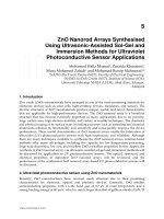
ZnO Nanorod Arrays Synthesised
Using Ultrasonic-Assisted Sol-Gel and
Immersion Methods for Ultraviolet
Photoconductive Sensor Applications
Mohamad Hafiz Mamat
1
, Zuraida Khusaimi
2
,
Musa Mohamed Zahidi
1
and Mohamad Rusop Mahmood
1,2
1
NANO-ElecTronic Centre (NET), Faculty of Electrical Engineering;
2
NANO-SciTech Centre (NST), Institute of Science (IOS);
Universiti Teknologi MARA (UiTM), Shah Alam, Selangor,
Malaysia
1. Introduction
Zinc oxide (ZnO) nanomaterials have emerged as one of the most promising materials for
electronic devices such as solar cells, light-emitting devices, transistors, and sensors. The
diverse structures of ZnO nanomaterials produce unique, useful, and novel characteristics
that are applicable for high-performance devices. The ZnO nanorod array is a beneficial
structure that has become extremely important in many applications due to its porosity,
large surface area, high electron mobility, and variety of feasible techniques. The chemistry
and physical tuning of its surface state, including processes such as annealing and chemical
treatments, enhance its functionality and sensitivity and consequently improve the device
performance. These useful characteristics of ZnO nanorod arrays enable the fabrication of
ultraviolet (UV) photoconductive sensors with high responsivity and reliability. Although
there are many techniques available to synthesise the ZnO nanorod arrays, solution-based
methods offer many advantages, including the capacity for low-temperature processing,
large-scale deposition, low cost, and excellent ZnO crystalline properties. In this chapter, the
synthesis of ZnO nanorod arrays via ultrasonic-assisted sol-gel and immersion methods will
be discussed for application to UV photoconductive sensors. The optical, structural, and
electrical properties of deposited ZnO nanorod arrays will be reviewed, and the
performance of the synthesised ZnO nanorod array-based UV photoconductive sensors will
be discussed.
2. Ultraviolet photoconductive sensor using ZnO nanomaterials
Recently, ZnO nanostructures have received much attention due to their promising
characteristics for electronic, optical, and photonic devices. Generally, ZnO exhibits
semiconducting properties with a wide band gap of 3.3 eV at room temperature and a
strong binding energy of 60 meV, which is much larger than that of gallium nitride (GaN, 25
www.intechopen.com
Nanorods
94
meV) or the thermal energy at room temperature (26 meV). ZnO is naturally an n-type
semiconductor material that is very transparent in the visible region, especially as a thin
film, and has good UV absorption. ZnO is a biosafe and biocompatible material that has
many applications, such as in electronics and biomedical and coating technologies. A
reduction in size of the ZnO particle to the nanoscale level produces novel and attractive
electrical, optical, mechanical, chemical, and physical properties due to quantum
confinement effects. Moreover, ZnO nanostructures have a high aspect ratio, or a large
surface-to-volume ratio and high porosity, which can fulfil the demand for high
performance and efficiency in numerous applications (Lee et al., 2009, Galoppini et al., 2006,
Park et al., 2011, Hullavarad et al., 2007).
UV photoconductivity, where the electrical conductivity changes due to the incident UV
radiation, is characteristic of few semiconductors (wide band gap) or materials. This
characteristic involves a number of mechanisms, including the absorption of light, carrier
photogeneration, and carrier transport (Soci et al., 2010). Generally, a change in conductivity
is related to the number of photogenerated carriers per absorbed photon or quantum yield
and the mobility of the photogenerated carriers. The photoresponse time usually involves
factors such as carrier lifetime and the defects state of the material. In other words, the UV
photoconductivity represents important electrical properties that are related to carrier
mobility, carrier lifetime, and defects in the materials.
There are various reports regarding UV photoconductive sensors that utilise ZnO
nanostructures as the sensing elements. For example, Pimentel et al. developed ZnO thin-
film-based UV sensors using radio frequency (RF) magnetron sputtering (Pimentel et al.,
2006). They produced ZnO thin films with resistivities from 5 x10
4
to 1 x10
9
Ω cm and
revealed that the preparation of ZnO films without oxygen exposure in an RF sputtering
chamber produced a UV detector with higher sensitivity at thicknesses below 250 nm than
ZnO films with oxygen exposure. They theorised that the result might have been due to the
smaller grain size of the ZnO films without oxygen exposure, which increased the sensor
active areas for UV detection.
Additionally, Xu et al. developed an Al-doped ZnO thin-film-based UV sensor using the sol-
gel method (Xu et al., 2006). They produced a 5 mol % Al-doped ZnO film that was highly
oriented along the c-axis of a Si (111) substrate. Their study detailed the suitability of Al-
doped ZnO thin films for UV detection, where a high photocurrent value was obtained
when the film was irradiated with UV light between 300 nm and 400 nm. However, their
study revealed that the cut-off wavelength of Al-doped ZnO was blue-shifted to a shorter
wavelength compared with the undoped film. They also observed that the photocurrent
value of the Al-doped ZnO film in the visible region was reduced slightly compared to the
undoped ZnO film, which improved the UV sensor sensitivity.
Zheng et al. developed a photoconductive ultraviolet detector based on ZnO films (Zheng et
al., 2006). The ZnO thin films were deposited by pulsed laser deposition (PLD) at a thickness
of 300 nm on glass substrates. Al metal contacts with 0.1 mm separation were deposited
onto the ZnO films to complete the UV photoconductive sensor configuration. The
crystallite size of the PLD-deposited ZnO film was around 23 nm, and the ZnO films grew
along the c-axis, or perpendicular to the substrate. They found that the crystallite
boundaries that were induced by the small crystallite size of the ZnO nanoparticles
www.intechopen.com
ZnO Nanorod Arrays Synthesised Using Ultrasonic-Assisted
Sol-Gel and Immersion Methods for Ultraviolet Photoconductive Sensor Applications
95
contributed to the oxygen adsorption at the interfaces of the ZnO crystallites. This condition
also resulted in carrier scattering, which decreased the carrier mobility. They also observed
that the ZnO-nanoparticles based UV detector from their method showed a large dark
current of approximately 0.2 mA at a bias voltage at 5 V, which was due to intrinsic defects,
such as oxygen vacancies and zinc interstitials.
Jun et al. fabricated ultraviolet photodetectors based on ZnO nanoparticles with a diameter
size of 70 nm using a paint method on thermally oxidised Si substrate (Jun et al., 2009). They
used gold as the metal contacts with a gap of 20 μm. They addressed the surface defect
problem experienced by nanoparticle-based UV detectors. Surface defects cause a rise time
delay during UV illumination and irradiative recombination between the holes and
electrons, which lowers the performance of ZnO nanoparticle-based devices.
Liu et al. fabricated a ZnO/diamond-film-based UV photodetector on a Si substrate (Liu et
al., 2007). The ZnO films were deposited on a freestanding diamond-coated Si substrate by
RF magnetron sputtering. They used gold as the metal contacts, which were deposited onto
the film by DC magnetron sputtering with 2 mm of electrode separation. They found that
the dark current of their UV sensor decreased with the grain size, which was due to the
reduction of the ZnO grain boundaries. It was also mentioned that the ZnO-film-based UV
photodetector showed a slow photoresponse due to a carrier-trapping or polarisation effect.
Hullavarad et al. developed UV sensors based on nanostructured ZnO spheres in a network
of nanowires (Hullavarad et al., 2007). They produced the nanostructured ZnO using a
direct vapour phase (DVP) technique. The sizes of the microspheres varied from 600 nm-2
μm, while the nanowire diameters were 30-65 nm. Based on their analysis, the dark current
value of their sensor was 1 x 10
-10
A at 1 V, which is less than the dark current of a ZnO thin
film-based sensor reported by Yang et al. (Yang et al., 2003) and is a result of the low
surface-defect properties of their ZnO nanostructures, as observed in the photoluminescence
(PL) spectra.
Another interesting study that utilised a single nanobelt as a UV photoconductive sensor
was conducted by Yuan et al. (Yuan et al., 2011). The nanobelt has a very similar structure as
the nanorod, except the nanobelt exists in a box-like dimension where it has height
(nanobelt thickness), width and length. In this case, the prepared nanobelt had a thickness of
120 nm and a width of 600 nm. With this structure, a sensor was constructed with a
photocurrent value that was four orders of magnitude higher than the dark current. The
sensor also possessed other excellent performance features, such as a high photosensitivity
of 10
4
, a low dark current of 10
-3
µA, a low power consumption of 2.45 µW, a typical rise
time of 0.12 s, and a decay time of 0.15 s. They explained that the high surface-to-volume
ratio and the high coverage-area-to-total-area ratio contributed to the superior performance
of their device.
A UV photoconductive sensor using a film of ZnO nanowall networks has been fabricated
by Jiang et al. (Jiang et al., 2011). The films were prepared on a Si (111) substrate using
plasma-assisted molecular beam epitaxy, with the inner diameters of the nanowalls ranging
from 100 to 500 nm. In their sensor configuration, 200 nm-thick Au metal contacts were
deposited in an interdigitated electrode design with electrode fingers that were 5 µm wide,
500 µm long, and on a pitch of 2 µm. The sensor showed a huge response to 352 nm UV
light, with a responsivity of 24.65 A/W under a biased voltage of 5 V. The cut-off
www.intechopen.com
Nanorods
96
wavelength of the sensor was approximately 360 nm. They showed that the nanostructure-
based device had a high photoconductive gain due to the presence of oxygen-related hole-
trap states on the nanowall surface.
Based on these previous studies, the use of nanostructure materials for UV photoconductive
sensor applications have many advantages over bulk structures, including high gain, low
power consumption, high sensitivity, reduced dimensionality, and the use of an extremely
small fraction of the device’s active materials. There are a number of factors that contribute
to the high photosensitivity of nanostructure-based devices, including the surface-to-volume
ratio, surface defects, light trapping, and porosity (Soci et al., 2007). Current research has
mainly focused on the fabrication of UV photoconductive sensors using ultra-small
nanostructures that contribute to the large surface area of the sensing element. Research has
also emphasised prolonging the carrier lifetime of the device during UV illumination to
lower the charge-carrier recombination. The carrier transit time also plays an important role
in the device performance; thus, high mobility nanostructures are needed for good device
performance.
3. ZnO nanorod arrays in ultraviolet photoconductive sensor
Currently, ZnO nanorods are receiving considerable attention for UV photoconductive
sensor applications due to their unique characteristics and quantum confinement properties.
The nanorod structure shows good surface area availability with excellence carrier transport
characteristics that are very suitable for UV sensor applications. Depending on the method
and experimental parameters used, the nanorod sizes (i.e., diameter and length) are
tuneable, which may give different sensor performances. Additionally, by modifying the
surface, the performance of the sensor can also be improved because of the relationship
between surface defects and surface adsorption of gas molecules from the atmosphere,
which tremendously influence the sensor characteristics. According to Soci et al., one-
dimensional (1D) structures have several advantages over bulk or thin films in UV sensor
applications, including light scattering enhancements that reduce optical losses, improved
light absorption, large photosensitivity due to the high gain, and the possibility to integrate
functionalities within single 1D devices (Soci et al., 2010). The prolonged photocarrier
lifetime, which is due to charge separation promoted by surface states, and the reduction in
carrier transit time, which can be achieved in high-quality, low-defect ZnO nanorod
together with small gap of metal contacts, both contribute to the high gain in the nanorod-
based devices.
Surface area plays a very important role in the UV sensing mechanism, as the sensing
mechanism involves the surface reactions between free carriers and the surrounding
environment, such as oxygen molecules and humidity (Mamat et al., 2011). The nanorod
area possesses a high surface area on the film surface that is suitable for UV
photoconductive sensor applications. Moreover, these nanorods exhibit higher carrier
mobility than that of ZnO nanoparticles, which works effectively during the surface reaction
process. Generally, the photoresponse of a UV photoconductive sensor is influenced by the
adsorption and desorption of oxygen on its surface during UV illumination. Oxygen
molecules from the surrounding are adsorbed onto the nanorod surface by capturing free
electrons from ZnO, as shown in the following equation (Su et al., 2009, Zheng et al., Lupan
et al., 2010):
www.intechopen.com
ZnO Nanorod Arrays Synthesised Using Ultrasonic-Assisted
Sol-Gel and Immersion Methods for Ultraviolet Photoconductive Sensor Applications
97
22
Oe O
−−
+→
(1)
where O
2
is an oxygen molecule, e
-
is a free electron, and
2
O
−
is an adsorbed oxygen on the
nanorod surface. When the UV light is incident on the nanostructure surface, electron-hole
pairs are photogenerated according to the following equation:
hv h e
+−
→+ (2)
where hv is the photon energy of UV light, h
+
is a photogenerated hole in the valence band
and e
-
is a photogenerated electron in the conduction band. A large surface area availability
in the nanorod film facilitates a fast surface reaction process as the photogenerated hole
reacts with a negatively charged adsorbed oxygen, as shown by:
22
Oh O
−+
+→
(3)
This condition leaves behind the electron of the pair, which increases the conductivity of the
nanostructures. When the illumination is turned off, the oxygen molecule recombines with
the electron, leading to a decrease in film conductivity.
This sensor behaviour that is related to the adsorption and desorption of oxygen was
studied by Jun et al. (Jun et al., 2009). They measured their fabricated UV sensor under
different atmospheric pressures (0.1-1 atm), with different oxygen levels. They found that
the photoresponse decay time constant of the sensor increased with decreasing atmospheric
pressure. Because the lower atmospheric pressure had a lower oxygen content, it reduced
the ability of the sensor to return to its initial state (dark current) due to a reduction of
oxygen adsorption onto the ZnO surface. This condition increased the decay time constant
of the device as the atmospheric pressure was lowered.
Basically, the nanorod-based UV photoconductive sensor represents the simplest
configuration of the UV sensor. It consists of just the nanorods and metal contacts for the
photogenerated carrier transport to the outer circuit. In this UV photoconductive sensor
configuration, ZnO nanorods are used either vertically or horizontally with the substrates.
The vertical standing nanorod is commonly used in an array form or a film-based sensor,
while the horizontal nanorod is used in single-nanorod-based sensors. However, a single-
nanorod-based UV sensor is very complicated and involves a very challenging fabrication
process using high-cost instruments. The realisation of single-nanorod-based UV sensors
might reduce the size and the power consumption of the UV sensor. For example, a single-
ZnO-nanorod-based UV sensor has been fabricated by Chai et al. (Chai et al., 2011). They
used chemical vapour deposition (CVD) method to synthesise a ZnO nanorod with a
diameter approximately 1-3 µm and a length of 20-200 µm. To fabricate the UV sensor, a
focused ion beam (FIB) in situ lift-out technique was used. In their sensor configuration,
Au/Ti metal electrodes separated by 20 µm were used. They showed that the single
nanowire had a good response to UV light, where the resistance decreased from 52.4 to 48.0
kΩ during 365 nm UV illumination with an optical power of 0.1 mW.
A nanorod array-based UV photoconductive sensor is a promising device structure that has
an easier fabrication process compared to a single nanorod-based UV sensor. Moreover, it
produces large photocurrent signals due to the large surface coverage and nanorod density.
www.intechopen.com
Nanorods
98
Various techniques are available to fabricate the ZnO nanorod array, including metal-
organic chemical vapour deposition (MOCVD), CVD, sputtering, and solution-based
synthesis. Solution-based synthesis has shown promising results for producing aligned ZnO
nanorod arrays. This technique is simple, versatile, low-temperature and can be used for
large-scale depositions. Another advantage of this technique is that it is a vacuum and gas-
free deposition method in which the chemical reactions completely depend on the prepared
solution. The biggest advantage of this method is its low-temperature processing, which
could even be used to deposit nanostructures on polymer substrates. Unlike other methods
that require high temperature for nanostructure growth, this hydrothermal synthesis can be
operated at temperatures as low as 50°C for the deposition of ZnO nanostructures (Niarchos
et al., 2010).
4. Synthesis of ZnO nanorod arrays via ultrasonic-assisted sol-gel and
immersion methods
Recently, ultrasonic irradiation has been applied in hydrothermal processes to prepare ZnO
nanostructures. This sonochemical methods use ultrasound irradiation at ranges between 20
kHz to 10 MHz (Suslick et al., 1991). For example, Mishra et al. have synthesised flower-like
ZnO nanostructures using a starch-assisted sonochemical method (Mishra et al., 2010). Jia et
al. also produced ZnO nanostructures using a sonochemical method (Jia et al., 2010). Using
ultrasonic irradiation, they produced hollow ZnO microspheres during hydrothermal
synthesis. Another example of ultrasonic-assisted hydrothermal synthesis is a study
performed by Mazloumi et al. They produced cauliflower-like ZnO nanostructures using a
sonochemical method (Mazloumi et al., 2009). The products that were synthesised by the
three sonication methods were similar in that they consisted of powder-form
nanostructures. Unfortunately, the powder-forms structures require a seperate process to
deposit them onto the substrate for electronic device applications.
In our process, we apply ultrasonic irradiation to the precursor solution, which is used to
grow ZnO nanorod arrays on a seed-layer-coated substrate using an immersion process. The
sonication process uses powerful ultrasound radiation that can induce molecules to undergo
chemical reactions. Sonication is usually used in cleaning processes to remove
contaminations, such as substrate and glass wear, from solid surface. Ultrasound radiation
involves the creation, growth and collapse of bubbles that can break the chemical bonds of
materials in a liquid medium. Generally, growing nanomaterials using a chemical solution
method requires a precursor, stabiliser, and solvent. The precursor material supplies the
main atoms or ions of the nanomaterials, while the stabiliser material is used to ensure that
the growth of the nanomaterial is controlled to a specific rate or structure. The reaction
process between the stabiliser and the precursor material prevents the nanomaterials from
growing too fast in a certain direction or plane. However, if the reaction process between the
precursor and stabiliser does not occur uniformly throughout the solution (e.g., due to
agglomerated precursor materials at the beginning or early stages), the size of the end
product materials will be large, consequently reducing the surface area. This condition
reduces the quantum confinement effect in the produced nanomaterials. In our case, we
apply sonication to rupture agglomerated precursor and stabiliser materials and, at the
same time, ensure a highly homogenous and uniform reaction process between the
precursor and stabiliser.
www.intechopen.com
ZnO Nanorod Arrays Synthesised Using Ultrasonic-Assisted
Sol-Gel and Immersion Methods for Ultraviolet Photoconductive Sensor Applications
99
ZnO nanorod array films were fabricated using an ultrasonic-assisted sol-gel and immersion
method using zinc nitrate hexahydrate (Zn(NO
3
)
2
·6H
2
O) as a precursor,
hexamethylenetetramine (HMT, C
6
H
12
N
4
) as a stabiliser, and aluminium nitrate
nonahydrate (Al(NO
3
)
3
·9H
2
O, 98 %, Analar) as a dopant (Mamat et al., 2010). Aluminium
(Al) doping is especially attractive because it contributes to the higher conductivity of the
film without deteriorating the optical and crystalline properties of the ZnO. The precursor,
stabiliser, and dopant were dissolved in deionised (DI) water before being subjected to the
sonication process using an ultrasonic water bath (Hwasin Technology Powersonic 405, 40
kHz) for 30 min at 50°C. Subsequently, the solution was stirred and stored at room
temperature for 3 h.
Next, the solution was poured into a vessel, where the seed-layer–coated glass substrate was
positioned at the bottom of the vessel. The seed layer, or Al-doped ZnO nanoparticle layer,
was coated onto the substrate with a thickness of approximately 200 nm using sol-gel spin-
coating (Mamat et al., 2010). The existence of the seed layer on the glass substrate reduced
the formation energy for the crystallisation of the ZnO and, thus, helped the nanorod grow
more easily on the glass substrate. The vessel was then sealed before being immersed into a
water bath for 4 h at 95°C. After the immersion process, the sample was removed from the
vessel and rinsed with DI water. The sample was then dried at 150°C for 10 min and
annealed at 500°C for 1 h in a furnace. Next, 60-nm-thick Al metal contacts were deposited
onto the nanorod array using thermal evaporation to complete the sensor structure. The
distance between the electrodes was approximately 2 mm.
The surface morphologies of the ZnO nanorod array films were observed by field-emission
scanning electron microscopy (FESEM, ZEISS Supra 40VP and JEOL JSM-7600F). The surface
topology of the nanorod arrays was characterised using atomic force microscopy (AFM, Park
System). The crystallinity of the samples was investigated using X-ray diffraction (XRD,
Rigaku Ultima IV). The transmittance and absorbance characteristics of the seed layer and the
thin film were characterised using an ultraviolet-visible (UV-Vis) spectrophotometer (Perkin
Elmer Lambda 750). The photoluminescence (PL) properties of the synthesised nanorods were
investigated using a PL spectrophotometer with a helium-cadmium (He-Cd) excitation laser
operating at 325 nm (PL, Horiba Jobin Yvon-79 DU420A-OE-325). The UV photoresponse
measurements of the fabricated sensor were conducted using a spectral sensitivity analysis
system (Bunko-Keiki, CEP 2000) with a monochromatic xenon (Xe) lamp operating at 365 nm
and a power intensity of 5 mW/cm
2
as well as photocurrent measurement system operating at
365 nm and a power density of 750 µW/cm
2
. The thicknesses of the samples were measured
using a surface profiler (VEECO/D 150+). The fabrication process of the ZnO-nanorod-based
UV photoconductive sensor is shown in Fig. 1.
5. Performance of synthesised ZnO-nanorod-array-based ultraviolet
photoconductive sensor
We have investigated the performance of the ZnO-nanorod-array-based UV
photoconductive sensor prepared via ultrasonic-assisted sol-gel and immersion methods.
There are numerous factors that influence the sensor performance, such as nanorod size,
surface area, surface defects, film thickness, metal contacts, and doping. In this subchapter,
we will highlight the effects of surface modifications, film thickness, and Al ions doping on
the performances of the fabricated ZnO-nanorod-array-based UV sensor.
www.intechopen.com
Nanorods
100
Fig. 1. Fabrication process of aligned ZnO nanorod array-based UV photoconductive sensor
via sonicated sol-gel and immersion methods.
5.1 Surface modification
A ZnO nanorod array was prepared on glass substrate utilising an Al-doped ZnO
nanoparticle thin film catalytic seed layer. Figure 2(a) shows a field-emission scanning
electron microscopy (FESEM) image of the seed layer that was prepared using the sol-gel
spin-coating technique. The particle sizes of the Al-doped ZnO nanoparticles were
estimated to range from 10 to 40 nm. From the FESEM figure, synthesised Al-doped ZnO
nanoparticles exhibited some edges rather than perfect curved surfaces due to the
differenced in the surface energy of crystallographic directions of the ZnO growth. In the
wurtzite structure, the relative growth rate of each crystallographic plane differed
somewhat according to the crystal orientation, so it was difficult for crystalline ZnO to grow
symmetrically into spherical particles (Lee et al., 2007). The FESEM figure also indicates that
the particles were well connected to each other and that it was very important to develop a
continuous transport pathway in the granular film for electron movement in the UV sensor
application. Figure 2(b) shows an AFM image of the seed catalyst layer. Based on the AFM
image, the root mean square (RMS) roughness of the Al-doped ZnO nanoparticle thin film
was 17.51 nm over an area of 100 µm
2
.
In the UV photoconductive sensor, this seed layer plays a very important role in increasing
the sensor performance. Generally, one of the factors that degrades the sensor performance
is the strain of the film or the material, which influences the density of the defects and the
photoelectric activity of the sensor (Shinde & Rajpure, 2011). This seed layer facilitates the
homogenous growth of the compressive-strained layer, i.e., the high quality ZnO nanorod
material, which has a low defect density and allows for a smooth charge transfer process
during UV photo-illumination. As a result, the seed layer results in a higher responsivity of
the ZnO-nanorod-array-based UV photoconductive sensor.
www.intechopen.com
ZnO Nanorod Arrays Synthesised Using Ultrasonic-Assisted
Sol-Gel and Immersion Methods for Ultraviolet Photoconductive Sensor Applications
101
Fig. 2. (a) FESEM image of Al-doped ZnO nanoparticle thin film seed layer. (b) AFM
topography image of the seed layer.
Figure 3 shows an FESEM image of the Al-doped ZnO nanorod array before (Fig. 3(a)) and
after (Fig. 3(b) and 3(c)) the annealing process at 500°C. The nanorods were prepared using a
1000 ml solution that was sonicated in a beaker. The images show that well-oriented,
hexagonal-shaped ZnO nanorod arrays were deposited onto the seed-layer-coated glass
substrate with good uniformity and high density. The diameters and lengths of the
nanorods were not strongly affected by the annealing process, as the diameter of the
nanorods ranged between 40 to 150 nm and the nanorods were 1.1 μm long. The nanorods
were aligned well, which indicates that this low-temperature ultrasonic-assisted sol-gel and
immersion processes produce high-quality ZnO nanorod arrays. We believe that the
excellent alignment of the nanorod arrays is due to the seed layer films, which act as
nucleation centres that provide an almost mismatch-free interfacial layer between the
nanorods and the seed layers. This layer assists an epitaxial nanorod growth process on the
seed-layer-coated glass substrates. Figure 3(d) shows an AFM topography image of an
annealed ZnO nanorod array measured in a 1 µm
2
area. Based on this topography image,
the root mean square (RMS) roughness of the nanorod array was approximately 21.95 nm.
As shown in Fig. 3(b) and 3(c), nanoholes appeared on the surfaces of the nanorods after the
annealing process. A closer look at the cross-sectional images indicates that nanoholes exist
on nearly the entire nanorod surface. We suspect that these nanoholes are the result of the
evaporation of impurities, such as hexamethylenetetramine (HMT), during the annealing
process at high temperature. Interestingly, these nanoholes facilitate a larger surface area
availability of the single nanorod and facilitate effective sites for the oxygen adsorption
process. Thus, the existence of these nanoholes on the nanorod surface could improve the
performance of the UV photoconductive sensor because of the increased surface area and
surface photochemistry. The condition of the Al-doped ZnO nanorod with nanoholes after
annealing process is shown in Fig. 4.
XRD spectra of the as-grown nanorods and the 500°C annealed nanorods are shown in
Figure 5. The spectra confirmed that the synthesised nanorods belong to the ZnO hexagonal
wurtzite structure (joint committee on powder diffraction standards (JCPDS) PDF no. 36-
1451). Both the as-grown and annealed samples contained a dominant XRD peak at the
www.intechopen.com
Nanorods
102
Fig. 3. FESEM image of (a) as-grown and (b) 500°C annealed Al-doped ZnO nanorod arrays.
(c) Cross-sectional image of the annealed Al-doped ZnO nanorod arrays, clearly showing
nanoholes on the ZnO surface. (d) AFM image of the annealed Al-doped ZnO nanorod
array.
Fig. 4. Nanoholes produced on the surface of the nanorod after the annealing process as a
result of the evaporation of impurities.
(002)-plane, implying that the nanorods were grown along the c-axis, or perpendicular to
the substrates. This result indicates that the Al-doped ZnO nanorod arrays prepared in this
work had a very good ZnO crystal quality. The weak peaks intensities of the other
orientations might be due to the vertical alignment imperfections of the nanorods (Qiu et al.,
2009). Based on the spectra, the peak intensities of the annealed nanorods were higher than
the as-grown sample, indicating an improvement in the nanorod crystallinity after the
annealing treatment. Based on these results, we predicted a possible growth mechanism for
www.intechopen.com
ZnO Nanorod Arrays Synthesised Using Ultrasonic-Assisted
Sol-Gel and Immersion Methods for Ultraviolet Photoconductive Sensor Applications
103
the formation of the well-aligned ZnO nanorod arrays on the seed-layer-coated glass
substrate using the ultrasonic-assisted sol-gel and immersion methods (Mamat et al., 2011).
We suspect that the growth along the c-axis might be caused by the effects of the sonication
process on the precursor solution, which disperses and mixes the zinc nitrate (i.e., the
precursor), aluminium nitrate (i.e., the dopant), and the HMT (i.e., the stabiliser) very well.
The sonication process also helps dissolve the agglomerated zinc nitrate and HMT particles,
which hasten the physical and chemical reaction activity in the solution. This process
enables the Zn
2+
ion to react effectively with the HMT, as shown by (Khusaimi et al., 2010)
Zn(NO
3
)
2
+ C
6
H
12
N
4
→ [Zn(C
6
H
12
N
4
)]
2+
+ 2NO
3
−
(4)
The HMT plays a very important role in controlling the growth of the aligned ZnO
nanorods. When it attaches to the Zn
2+
ions, particle agglomeration is reduced and ZnO
formation in the solution is slowed.
Fig. 5. XRD patterns of Al-doped ZnO nanorod array before (as-grown) and after annealing.
During the hydrothermal process, the seed catalyst layer provides a base that initiates the
growth of the nanorod arrays through heterogeneous nucleation. It is generally accepted
that heterogeneous nucleation on a seed layer surface occurs more easily than does
homogenous nucleation (Guo et al., 2005). The seed layer provides the lowest energy barrier
for heterogeneous nucleation, which produces almost negligible lattice mismatch between
the nanorods (Chen et al., 2009, Giri et al., 2010). This condition results in the growth of
high-quality aligned nanorod arrays on the substrates. The general reactions occurring
during the hydrothermal process can be described by the following equations (Khusaimi et
al., 2010, Lupan et al., 2007):
C
6
H
12
N
4
+ 4H
2
O ⇌ C
6
H
12
N
4
H
4
+
+ 4OH
−
(5)
[Zn(C
6
H
12
N
4
)]
2+
+ 4OH
−
→ Zn(OH)
4
2−
+ C
6
H
12
N
4
(6)
Zn(OH)
4
2−
→ Zn
2+
+ 4OH
−
(7)
Zn
2+
+ 2OH
−
⇌ ZnO + H
2
O or Zn
2+
+ 2OH
−
⇌ Zn(OH)
2
⇌ ZnO + H
2
O (8)
www.intechopen.com
Nanorods
104
Initially, when the Zn
2+
and OH
−
ion concentrations exceed the boundaries of
supersaturation, ZnO nuclei form on the seed layer surface, initiating the growth of aligned
ZnO nanorods. It has been suggested that the HMT also acts as a chelating agent that
attaches to the nonpolar facets of ZnO nanorods (Sugunan et al., 2006). Because of this
attachment behaviour, epitaxial growth along the c-axis is facilitated because only the (0001)
plane is exposed during the growth process. Because the growth rate in the (0001) plane
proceeds the fastest in the hydrothermal system (Laudise & Ballman, 1960, Laudise et al.,
1965), the ZnO nanorods grow preferentially in the (0001) plane, which is vertically aligned
with the substrate.
Good dispersion and mixing processes between the precursor and the stabiliser through
sonication help control the diameter sizes of the nanorods because the HMT can immediately
attach onto the nonpolar facets (i.e., six prismatic side-planes) after the ZnO nanorod
nucleation process is initiated on the seed layer. The HMT acts as a buffer layer at the nonpolar
surfaces, which disturbs the ZnO deposition onto these surfaces. This condition disables rapid
growth on the side walls, or the nonpolar surface of the nanorod, which served to maintain an
almost constant diameter size throughout the length. The rapid attachment of the HMT onto
the ZnO surface prevents any nanorod growth in the direction of the nonpolar facets, thus
hindering an enlargement in the nanorod diameter. Therefore, because the ZnO nanorods are
confined by the HMT molecules on their nonpolar surfaces and only grow from the polar
surface for further growth, directional growth along the c-axis is achieved.
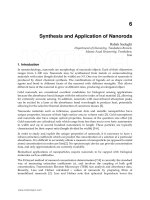
The photoluminescence (PL) spectra of the as-grown nanorod and the annealed nanorod
with nanoholes are depicted in Fig. 6. The main peaks that were observed in the spectrum of
the annealed nanorods are located at 380 and 580 nm, and the main peaks in the spectrum of
the as-grown nanorods is located at 380 and 590 nm. The UV emission at 380 nm
corresponds to free exciton recombination, while the orange emission at 580 and 590 nm are
related to the emission from defects, such as oxygen deficiencies and zinc interstitials.
According to Rosa et al., this orange emission is due to zinc interstitials that occur close to or
on the surface of the ZnO structure (De la Rosa et al., 2007). The shift in the visible emission
peak from 590 to 580 nm for annealed nanorods might be due to the desorption of the OH
groups from the nanorod surface (Lee et al., 2010). The as-grown nanorods exhibited a very
weak UV emission peak intensity compared to the annealed nanorods. The annealing
process increased the UV emission peak intensity, which indicates that the crystallinity of
the sample improved at the higher annealing temperatures.
During the annealing treatment, the concentrations of defects in the nanorods were reduced
according to equations (9-10) shown below (Lin et al., 2001):
2
1
2
OO
VOO+= (9)
2
1
2
iZnO
Zn O Zn O+= +
(10)
where V
O
is an oxygen vacancy, Zn
i
is a zinc interstitial, and Zn
Zn
and O
O
represent zinc and
oxygen at a lattice site, respectively. Because the supplied thermal energy induces an
oxygenation process during the annealing treatment, oxygen from the atmosphere occupies
the vacant sites of the ZnO lattice, which eventually reduces both the zinc interstitial and
www.intechopen.com
ZnO Nanorod Arrays Synthesised Using Ultrasonic-Assisted
Sol-Gel and Immersion Methods for Ultraviolet Photoconductive Sensor Applications
105
oxygen vacancy concentrations. To investigate this phenomenon, we calculated the ratio of
the UV emission intensity over the visible emission intensity to be 0.6 and 7.1 for the as-
grown and the 500°C annealed nanorods, respectively. It is generally accepted that this ratio
value is a good way to evaluate the optical quality and stoichiometric properties of ZnO. An
increase of this ratio indicates that the stoichiometric properties of ZnO and its optical
properties were improved after the annealing process. Lee et al. reported that the ratio of the
UV peak intensity over the visible peak intensity is directly related to the oxygen deficiency
in the ZnO nanorods (Lee et al., 2010). Based on this ratio analysis, the defect concentrations
from oxygen vacancies and zinc interstitials were suppressed during the annealing
treatment, as indicated by in equations (9-10). The reduction of defect concentrations in the
nanorods strengthened the UV emission and reduced the visible emission of the nanorods
after the annealing process.
350 400 450 500 550 600 650 700 750
0.1
0.2
0.3
0
1
2
3
350 400 450 500 550 600 650 700 750
I
UV
/I
VIS
= 0.64
I
UV
/I
VIS
= 7.09
Intensity (x 10
3
cps)
Wavelength (nm)
As-Grown
500 °C
Fig. 6. Room temperature PL spectra of the as-grown and annealed ZnO nanorod arrays.
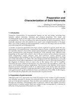
Figure 7 shows the time-dependent photocurrent properties of the fabricated UV
photoconductive sensors under a bias voltage of 10 V. The measurements were conducted
using 365 nm UV illumination with an optical power density of 5 mW/cm
2
. Both the as-
grown and annealed nanorods showed a response to the UV light but with different sensing
characteristics. The dark currents/photocurrents of the fabricated devices were 3.49 x 10
-6
A/4.08 x 10
-4
A and 1.78 x 10
-6
A/1.35 x 10
-4
A for the annealed and as-grown nanorods,
respectively. The responsivity of the fabricated devices was calculated according to equation
(11) (Jun et al., 2009):
www.intechopen.com
Nanorods
106
p
hdark
op
II
R
P
−
=
(11)
where
p
h
I
is the photocurrent,
dark
I
is the dark current, and
op
P
is the optical power of the
UV source. For the annealed nanorod-array-based UV sensor, the calculated responsivity
was 1.35 A/W. For the as-grown nanorod-array-based UV sensor, the responsivity was 0.44
A/W. The desirable crystallinity properties and low defect concentrations of the annealed
nanorods may have contributed to the high responsivity of this sensor. The rise and decay
time constants for the fabricated sensors were estimated using equations (12-13) (Jun et al.,
2009, Li et al., 2009):
Rise process upon UV illumination ON:
0
1
r
t
II e
τ
−
=−
(12)
Decay process after UV illumination OFF:
0
d
t
IIe
τ
−
=
(13)
where
I is the magnitude of the current,
0
I
is the saturated photocurrent,
t
is time,
r
τ
is the
rise time constant and
d
τ
is the decay time constant. The calculations show that the
annealed Al-doped ZnO nanorod array-based UV sensor exhibited small rise and decay
time constants at 20 s and 22 s, respectively. For the as-grown sample, the rise time constant
was 280 s, while the decay time constant was estimated to be 300 s. This result indicates that
the annealing process greatly improved the performance of the UV sensor.
0 500 1000 1500 2000 2500 3000
0.0
0.1
0.2
0.3
0.4
As-grown nanorod
Annealed Nanorod
Photocurrent (mA)
UV On
UV Off
Time (s)
Fig. 7. Plot of the growth and decay of the photocurrent measured at 10 V of the as-grown
and annealed Al-doped ZnO nanorod array-based UV photoconductive sensors under 365
nm, 5 mW/cm
2
UV illumination.
www.intechopen.com
ZnO Nanorod Arrays Synthesised Using Ultrasonic-Assisted
Sol-Gel and Immersion Methods for Ultraviolet Photoconductive Sensor Applications
107
The annealing process plays an important role in improving the sensor performance and is
considered a surface treatment or surface modification. For example, Kim et al. reported that
water molecules and residual carbon from the fabrication process could be effectively
desorbed from the surface of a ZnO nanowire during the annealing process (Kim et al.,
2011). As a consequence, oxygen molecules from the air could occupy the existing defect
sites more easily, which contributed to a faster photocurrent decay, higher sensitivity, and
faster response when the UV light was turned off. Because their fabricated sensor consisted
of a ZnO nanowire network that depended on the interconnections between the nanowires
for the carrier transportation, the annealing process improved the contact between the
nanowire interfaces. As a result, the contact resistance was reduced, and the potential
barrier was lowered. Other important effects of the annealing process included an
improvement of the nanowire crystallinity and a reduction in defects, which also
significantly improved the photocurrent properties of the sensor.
Improvements of UV sensor performances from surface modifications have also been
reported by other groups. For instance, Park et al. showed that a larger photocurrent value
and faster photoresponse time were achieved for roughened ZnO nanorods in a UV
photodetector (Park et al., 2011). They demonstrated that the surfaces of the nanorods could
be roughened by immersing the nanorods in isopropyl alcohol (IPA) for 30 days. The etched
areas of the nanorod surfaces from IPA contained defects state that enhanced the adsorption
of oxygen molecules onto the surface. This condition resulted in a large quantity of oxygen
molecules that adsorbed onto the nanorod surfaces.
Another method for increasing the sensor responsivity involved the surface passivation of
ZnO nanorods by thin layer coating (e.g., with polyvinyl alcohol (PVA)). The idea is to
increase the photoluminescence (PL) UV emission of the ZnO while reducing the green
emission that is related to ZnO surface defects. Recent research on coating ZnO
nanoparticles with PVA has shown a suppression in the number of defects evidenced by a
reduction in the parasitic green emission (Qin et al., 2011). This characteristic increased the
ratio of the photocurrent over the dark current compared to the uncoated ZnO particles. The
coatings effectively decreased the number of holes in the deep level, which helped the UV-
excited electrons to recombine with the holes in the valence band without being trapped in
the deep-level defects of ZnO.
5.2 Role of nanorod array thickness
We investigated the performance of the UV sensor at different nanorod array thicknesses. In
this study, we prepared the nanorod array films at different thicknesses by varying the
immersion times from 1 to 5 h. In this case, we used a 100 ml solution in the vessel to grow
the Al-doped ZnO nanorod arrays. We have previously shown that the volume of solution
in the vessel affects the nanorod length or film thickness during the deposition process
(Mamat et al., 2011). Therefore, it was expected that the film prepared for this study would
be thinner than the nanorod array discussed in section 5.1. Figure 8 depicts FESEM images
of the Al-doped ZnO nanorod arrays at different immersion times. The sizes of the nanorod
diameters in the sample prepared after a 1 h immersion (Fig. 8(a)) ranged from 40 to 150 nm.
Notably, the diameters of the nanorods remained almost unchanged after increasing the
immersion time to 2, 4, and 5 h, as observed in Fig. 8(b), 8(c), and 8(d).
www.intechopen.com
Nanorods
108
Fig. 8. Top-view FESEM images of Al-doped ZnO nanorod arrays prepared at immersion
times of (a) 1, (b) 2, (c) 4, and (d) 5 h.
To investigate the growth behaviour, we performed thickness measurements to characterise
the lengths of the nanorods, i.e., the film thicknesses that were grown with at different
immersion times. The thicknesses of the nanorods were 629, 677, 727, 768, and 834 nm after
being immersed for 1,2,3,4, and 5 hours, respectively. From this result, we concluded that
the nanorod growth behaviour occurs primarily along the c-axis when the immersion
process is carried out at longer times. It is interesting to note that the nanorod dimension
increased only in length when immersed for longer times, without significantly affecting the
size of the nanorod diameter. This result indicates that the controllable growth of the
nanorods along the c-axis could be achieved under different immersion times using our
sonicated sol-gel immersion method while maintaining the diameter sizes of the nanorods.
It demonstrated that the sonication process provides a good dispersion process of the
starting materials to produce a mixture of zinc-aluminium-hexamethylenetetramine (Zn-Al-
HMT) complexes, which inhibit growth at the nonpolar surfaces of ZnO while promoting
growth along the c-axis, or polar surface, at longer immersion times.
Figure 9 shows the photoresponse spectra of the Al-doped ZnO nanorod array-based UV
sensor at different thicknesses. The photocurrent value of the UV sensor decreased with
increasing film thickness up to 834 nm. The decrease in photocurrent value with film
thickness also influenced the responsivity of the device, as it exhibited a lower value with
thicker films. The responsivity of the device was calculated to be 2.13, 1.75, 1.21, 0.94, and
0.83 A/W for sensors with thicknesses of 629, 677, 727, 768, and 834 nm, respectively.
Thicker films also increased the rise (decay) time constant of the devices. The rise (decay)
www.intechopen.com
ZnO Nanorod Arrays Synthesised Using Ultrasonic-Assisted
Sol-Gel and Immersion Methods for Ultraviolet Photoconductive Sensor Applications
109
process time constants of the device were calculated to be 3(12), 4(13), 6(15), 8(16), and 9(20)
s for 629, 677, 727, 768, and 834 nm-thick nanorod array-based UV sensors, respectively.
0 500 1000 1500 2000 2500 3000
0.00
0.02
0.04
0.06
0.08
0.10
0.12
0.02
0.04
0.06
0.08
0.10
0.02
0.04
0.06
0.02
0.04
0.06
0.01
0.02
0.03
0.04
0.05
727 nm
677 nm
629 nm
Time (s)
Photocurrent (mA)
UV ON
UV OFF
834 nm
768 nm
Fig. 9. UV photoresponse properties of Al-doped ZnO nanorod arrays at different
thicknesses under a 365 nm, 750 µW/cm
2
UV light at 10 V bias voltage.
In the UV sensor, the film has an optimum thickness for effectively detecting UV irradiation.
If the film is too thin, the UV light can pass through the film and not be fully absorbed
because the transmittance depth of light is proportional to its wavelength. Therefore, the
photocurrent value would be weak due to the low carrier photogeneration within the
limited absorbed UV light. A thicker film should increase the UV absorption, which would
result in an enhancement of the photocurrent value and responsivity of the UV sensor.
However, an excessively thick film would saturate the UV absorption and would not
contribute to an increase in photogenerated carriers. In this study, a reduction of
responsivity of the sensor with increasing film thickness might be influenced by the
extension of the diffusion lengths of the carriers to the metal contacts (Fu & Cao, 2006). An
increase in film thickness should increase the recombination probability of the electron-hole
pairs, leading to a decrease in photocurrent, and thus reducing the responsivity value of the
UV sensor. This phenomenon might also contribute to a larger rise (decay) time constant of
the device.
A similar observation of thickness-dependent UV photoconductive sensor was also reported
by Shinde et al. when they produced a gallium (Ga)-doped ZnO thin-film-based UV
photoconductive sensor fabricated using a spray pyrolysis method (Shinde & Rajpure, 2011,
2011). They found that by decreasing the Ga-doped ZnO thin film from 225 nm to 139 nm,
the responsivity of the sensor at a 5 V bias voltage at 365 nm improved from 1125 A/W to
1187 A/W.
www.intechopen.com
Nanorods
110
5.3 Aluminium doping effects
The doping process also plays an important role in the performance of the UV sensor. There
are several elements that could be used as a dopant in the nanorods, such as gallium (Ga),
indium (In), and aluminium (Al). In our study, we used Al ions doping because it could be
easily incorporated into the ZnO lattice and because it enhanced some of the ZnO nanorod
properties, such as optical transmittance and electrical conductivity. Furthermore, Al can
serve as a donor and induce chemical defects, which tremendously improve the optical and
electrical properties of ZnO (Yun & Lim, 2011).
Figure 10 shows the FESEM morphologies and cross-sectional images of undoped (Fig 10(a-
c)) and Al-doped ZnO nanorod arrays (Fig. 10(d-e)). In this experiment, we sonicated 500 ml
of the precursor solution in a smaller beaker to increase the ultrasonic power density
applied to the solution. We observed that the diameter sizes of nanorods decreased after Al
ions doping. The sizes of the undoped ZnO nanorods varied from 80 to 120 nm, while the
sizes of the Al-doped ZnO nanorods ranged from 30 to 70 nm. The reduction in size may
have originated from the different radii of Zn
2+
and Al
3+
ions, which are 0.074 nm and 0.054
nm, respectively. The existence of Al in the ZnO lattice may influence the attractive forces
between the atoms and thus reduce the diameter sizes of the ZnO nanorod. A similar
behaviour of the decrease in diameter was also reported by Hsu et al. (Hsu & Chen, 2010).
We also observed that the diameter sizes of Al-doped ZnO nanorods were smaller than
those of nanorods produced using a solution that was sonicated in a volume of 1000 ml, as
discussed in section 5.1 and 5.2. We suspect that the mixing process between the precursor
(i.e., zinc nitrate), stabiliser (i.e., HMT), and dopant (i.e., aluminium nitrate) was improved
by the stronger and more intense ultrasonic irradiation.
Figure 11 shows the photoresponse spectra of undoped and Al-doped ZnO nanorod array-
based UV photoconductive sensors under 365 nm UV illumination with an optical power
density of 750 µW/cm
2
. The spectra reveal that the Al-doped ZnO nanorod array-based UV
sensor almost doubled the magnitude of the photocurrent compared to the undoped ZnO
nanorod. The responsivity of the Al-doped ZnO-based UV sensor was 3.24 A/W, while the
responsivity of the undoped ZnO-based UV sensor was 1.60 A/W. From the calculation
results, we found that the rise (decay) process time constant of the undoped and Al-doped
ZnO nanorod array-based UV sensors were 16(16) and 3(10) s, respectively. This result
suggests that the Al-doped ZnO nanorod array improved the photoresponse of the sensor
by increasing the responsivity and decreasing the rise (decay) process time constant.
By adding Al, the carrier concentration of ZnO nanostructures were improved because the
substitution of Al
3+
at the Zn
2+
site created an extra free carrier in the process (Mridha &
Basak, 2007, Fournier et al., 2008). Because of the high electron concentration, this condition
reduced the barrier height between the Al-doped ZnO nanorod and the seed layer and
between the film and the Al metal contact interface. This reduction initially allowed the
photogenerated electrons to move more easily from the Al-doped ZnO nanorods to the seed
layer, then from the seed layer back to the Al-doped ZnO nanorods underneath the metal
contact, and finally to the metal contact. The flow of the photogenerated electrons during
UV illumination is depicted in Fig. 12. Additionally, Al ions doping led to a suppression of
defects in the film, such as zinc interstitials and oxygen vacancies, which served to increase
the stability and performance of the Al-doped ZnO film-based sensor (Mamat et al., 2011,
Sharma & Khare, 2010).
www.intechopen.com
ZnO Nanorod Arrays Synthesised Using Ultrasonic-Assisted
Sol-Gel and Immersion Methods for Ultraviolet Photoconductive Sensor Applications
111
Fig. 10. FESEM images of undoped (a-c) and Al-doped ZnO (d-e) nanorod arrays prepared
using 500 ml sonicated solution.
www.intechopen.com
Nanorods
112
0 500 1000 1500 2000 2500 3000
0.00
0.05
0.10
0.15
0.20
UV On
UV Off
Undoped ZnO Nanorod
Al-Doped ZnO Nanorod
Time (s)
Photocurrent (mA)
Fig. 11. The dependence of the photocurrent on operating time for undoped and Al-doped
ZnO-nanorod-array-based UV photoconductive sensors under 365 nm UV light with a
power density of 750 µW/cm
2
and a bias of 10 V.
Fig. 12. Flow of photogenerated carrier during UV illumination in ZnO-nanorod-array-
based UV photoconductive sensor
6. Conclusions
The performance of a UV photoconductive sensor using ZnO nanostructures, particularly
ZnO nanorod arrays, was discussed. The problems related with grain boundaries and poor
electron mobility have motivated researchers to develop ZnO nanostructure-based UV
sensors. The ZnO nanostructures which could be prepared in many shapes such as nanorod
and nanobelt might provide a way in improving electronic device performance through
reducing grain boundaries concentration and increasing the electron mobility in the
structure. Numerous techniques have been used to fabricate ZnO nanostructure-based UV
sensors, such as radio frequency (RF) magnetron sputtering, chemical vapour deposition
(CVD), sol-gel, molecular beam epitaxy (MBE), and pulsed laser deposition. Based on
previous studies, the use of nanostructure materials for UV photoconductive sensor
www.intechopen.com
ZnO Nanorod Arrays Synthesised Using Ultrasonic-Assisted
Sol-Gel and Immersion Methods for Ultraviolet Photoconductive Sensor Applications
113
applications have many advantages over bulk structures, including high gain, low power
consumption, high sensitivity, reduced dimensionality, and the use of an extremely small
fraction of the device’s active materials. There are a number of factors that contribute to the
high photosensitivity of nanostructure-based devices, such as the surface-to-volume ratio,
surface defects, light trapping, and porosity. Current research has mainly focused on the
fabrication of UV photoconductive sensors using smaller ZnO nanostructures that
contribute to the large surface area of the sensing element and prolonging the carrier
lifetime of the device during UV illumination to lower the charge-carrier recombination. The
nanostructures that have high carrier mobility also have been used to improve the transit
time of carriers, which results in the improvement of the device performance. A review of
the current status of the UV photoconductive sensor found that ZnO nanorods are very
promising nanostructures for UV detection due to their large surface area, high mobility,
and good surface photochemistry. However, there are still many challenges in the
fabrication of ZnO nanorod-based UV sensors because of certain ZnO defects that are
produced during the fabrication process. These defects eventually contribute to a lower
photoresponsivity, a low photogenerated carrier lifetime, and less effective UV light
absorption properties of the ZnO-nanorod-array-based UV sensor. In this chapter, we have
discussed the fabrication of ZnO-nanorod-array-based UV photoconductive sensors via
ultrasonic-assisted sol-gel and immersion methods. The fabrication of ZnO nanorod arrays
using a solution-based method is very attractive because of its simplicity, versatility, and
low-temperature processing. We found that several factors influence the UV sensor
performance, including surface treatment, film thickness, and doping of the ZnO nanorod
arrays.
7. Acknowledgements
The authors would like to thank Universiti Teknologi MARA (UiTM) Malaysia, Ministry of
Higher Education (MOHE) Malaysia, Jabatan Perkhidmatan Awam (JPA) Malaysia and
Research Management Institute (RMI) of UiTM for financial support. The authors would
also like to thank the Faculty of Applied Sciences (Mr. Hayub) and Faculty of Mechanical
Engineering, UiTM for their FESEM and XRD facilities, respectively. The authors thank Mr.
Shuhaimi Ahmad (UiTM technician), Mrs. Nurul Wahida (UiTM Asst. Science Officer) and
Mr. Mohd Azlan Jaafar (UiTM technician) for their kind support during this research.
8. References
Lee, J.M.; et al. (2009). ZnO Nanorod−Graphene Hybrid Architectures for Multifunctional
Conductors. The Journal of Physical Chemistry C, Vol.113, No.44, pp.19134, ISSN
1932-7447.
Galoppini, E.; et al. (2006). Fast Electron Transport in Metal Organic Vapor Deposition
Grown Dye-sensitized ZnO Nanorod Solar Cells.
The Journal of Physical Chemistry B,
Vol.110, No.33, pp.16159, ISSN 1520-6106.
Park, W.; et al. (2011). Enhancement in the photodetection of ZnO nanowires by introducing
surface-roughness-induced traps.
Nanotechnology, Vol.22, No.20, pp.205204, ISSN
0957-4484.
www.intechopen.com
Nanorods
114
Hullavarad, S.; et al. (2007). Ultra violet sensors based on nanostructured ZnO spheres in
network of nanowires: a novel approach.
Nanoscale Research Letters, Vol.2, No.3,
pp.161, ISSN 1931-7573.
Soci, C.; et al. (2010). Nanowire Photodetectors.
Journal of Nanoscience and Nanotechnology,
Vol.10, No.3, pp.1430, ISSN 1533-4880.
Pimentel, A.; et al. (2006). Role of the thickness on the electrical and optical performances of
undoped polycrystalline zinc oxide films used as UV detectors.
Journal of Non-
Crystalline Solids
, Vol.352, No.9-20, pp.1448, ISSN 0022-3093.
Xu, Z Q.; et al. (2006). Ultraviolet photoconductive detector based on Al doped ZnO films
prepared by sol-gel method.
Applied Surface Science, Vol.253, No.2, pp.476, ISSN
0169-4332.
Zheng, X.G.; et al. (2006). Photoconductive ultraviolet detectors based on ZnO films.
Applied
Surface Science
, Vol.253, No.4, pp.2264, ISSN 0169-4332.
Jun, J.H.; et al. (2009). Ultraviolet photodetectors based on ZnO nanoparticles.
Ceramics
International
, Vol.35, No.7, pp.2797, ISSN 0272-8842.
Liu, J.M.; et al. (2007). Effect of grain size on the electrical properties of ultraviolet
photodetector with ZnO/diamond film structure.
Journal of Crystal Growth, Vol.300,
No.2, pp.353, ISSN 0022-0248.
Yang, W.; et al. (2003). Compositionally-tuned epitaxial cubic Mg
x
Zn
1−x
O on Si(100) for deep
ultraviolet photodetectors
Applied Physics Letters, Vol.82, pp.3424, ISSN 1077-3118
Yuan, B.; et al. (2011). High photosensitivity and low dark current of photoconductive
semiconductor switch based on ZnO single nanobelt.
Solid-State Electronics, Vol.55,
No.1, pp.49, ISSN 0038-1101.
Jiang, D.; et al. (2011). Ultraviolet photodetectors with MgZnO nanowall networks grown by
molecular beam epitaxy on Si(1 1 1) substrates.
Materials Science and Engineering: B,
Vol.176, No.9, pp.736, ISSN 0921-5107.
Soci, C.; et al. (2007). ZnO Nanowire UV Photodetectors with High Internal Gain.
Nano
Letters
, Vol.7, No.4, pp.1003, ISSN 1530-6984.
Mamat, M.H.; et al. (2011). Fabrication of ultraviolet photoconductive sensor using a novel
aluminium-doped zinc oxide nanorod-nanoflake network thin film prepared via
ultrasonic-assisted sol-gel and immersion methods.
Sensors and Actuators A:
Physical
, Vol.In Press, Corrected Proof, ISSN 0924-4247.
Su, Y.K.; et al. (2009). Ultraviolet ZnO Nanorod Photosensors.
Langmuir, Vol.26, No.1,
pp.603, ISSN 0743-7463.
Zheng, X.G.; et al. Photoconductive properties of ZnO thin films grown by pulsed laser
deposition.
Journal of Luminescence, Vol.122-123, pp.198, ISSN 0022-2313.
Lupan, O.; et al. (2010). Ultraviolet photoconductive sensor based on single ZnO nanowire.
physica status solidi (a), Vol.207, No.7, pp.1735, ISSN 1862-6319.
Chai, G.Y.; et al. (2011). Fabrication and characterization of an individual ZnO microwire-
based UV photodetector.
Solid State Sciences, Vol.13, No.5, pp.1205, ISSN 1293-2558.
Niarchos, G.; et al. (2010). Growth of ZnO nanorods on patterned templates for efficient,
large-area energy scavengers.
Microsystem Technologies, Vol.16, No.5, pp.669, ISSN
0946-7076.
Suslick, K.S.; et al. (1991). Sonochemical synthesis of amorphous iron.
Nature, Vol.353,
No.6343, pp.414, ISSN 0028-0836.
www.intechopen.com
ZnO Nanorod Arrays Synthesised Using Ultrasonic-Assisted
Sol-Gel and Immersion Methods for Ultraviolet Photoconductive Sensor Applications
115
Mishra, P.; et al. (2010). Growth mechanism and photoluminescence property of flower-like
ZnO nanostructures synthesized by starch-assisted sonochemical method.
Ultrasonics Sonochemistry, Vol.17, No.3, pp.560, ISSN 1350-4177.
Jia, X.; et al. (2010). Using sonochemistry for the fabrication of hollow ZnO microspheres.
Ultrasonics Sonochemistry, Vol.17, No.2, pp.284, ISSN 1350-4177.
Mazloumi, M.; et al. (2009). Ultrasonic induced photoluminescence decay in sonochemically
obtained cauliflower-like ZnO nanostructures with surface 1D nanoarrays.
Ultrasonics Sonochemistry, Vol.16, No.1, pp.11, ISSN 1350-4177.
Mamat, M.H.; et al. (2010). Novel synthesis of aligned Zinc oxide nanorods on a glass
substrate by sonicated sol-gel immersion.
Materials Letters, Vol.64, No.10, pp.1211,
ISSN 0167-577X.
Mamat, M.H.; et al. (2010). Influence of doping concentrations on the aluminum doped zinc
oxide thin films properties for ultraviolet photoconductive sensor applications.
Optical Materials, Vol.32, No.6, pp.696, ISSN 0925-3467.
Lee, S.; et al. (2007). Fabrication of a solution-processed thin-film transistor using zinc oxide
nanoparticles and zinc acetate.
Superlattices and Microstructures, Vol.42, No.1-6,
pp.361, ISSN 0749-6036.
Shinde, S.S. & Rajpure, K.Y. (2011). High-performance UV detector based on Ga-doped zinc
oxide thin films.
Applied Surface Science, Vol.257, No.22, pp.9595, ISSN 0169-4332.
Qiu, M.; et al. (2009). Growth and properties of ZnO nanorod and nanonails by thermal
evaporation.
Applied Surface Science, Vol.255, No.7, pp.3972, ISSN 0169-4332.
Mamat, M.H.; et al. (2011). Controllable Growth of Vertically Aligned Aluminum-Doped
Zinc Oxide Nanorod Arrays by Sonicated Sol-Gel Immersion Method depending
on Precursor Solution Volumes.
Japanese Journal of Applied Physics, Vol.50, No.6,
pp.06GH04, ISSN 1347-4065.
Khusaimi, Z.; et al. (2010). Controlled Growth of Zinc Oxide Nanorods by Aqueous-Solution
Method.
Synthesis and Reactivity in Inorganic, Metal-Organic, and Nano-Metal
Chemistry
, Vol.40, No.3, pp.190 ISSN 1553-3174.
Guo, M.; et al. (2005). Hydrothermal growth of well-aligned ZnO nanorod arrays:
Dependence of morphology and alignment ordering upon preparing conditions.
Journal of Solid State Chemistry, Vol.178, No.6, pp.1864, ISSN 0022-4596.
Chen, Y.W.; et al. (2009). Size-Controlled Synthesis and Optical Properties of Small-Sized
ZnO Nanorods.
The Journal of Physical Chemistry C, Vol.113, No.18, pp.7497, ISSN
1932-7447.
Giri, P.K.; et al. (2010). Effect of ZnO seed layer on the catalytic growth of vertically aligned
ZnO nanorod arrays.
Materials Chemistry and Physics, Vol.122, No.1, pp.18, ISSN
0254-0584.
Lupan, O.; et al. (2007). Nanofabrication and characterization of ZnO nanorod arrays and
branched microrods by aqueous solution route and rapid thermal processing.
Materials Science and Engineering: B, Vol.145, No.1-3, pp.57, ISSN 0921-5107.
Sugunan, A.; et al. (2006). Zinc oxide nanowires in chemical bath on seeded substrates: Role
of hexamine.
Journal of Sol-Gel Science and Technology, Vol.39, No.1, pp.49, ISSN
0928-0707.
Laudise, R.A. & Ballman, A.A. (1960). Hydrothermal synthesis of zinc oxide and zinc
sulfide.
The Journal of Physical Chemistry, Vol.64, No.5, pp.688, ISSN 0022-3654.
www.intechopen.com
Nanorods
116
Laudise, R.A.; et al. (1965). Impurity content of synthetic quartz and its effect upon
mechanical Q.
Journal of Physics and Chemistry of Solids, Vol.26, No.8, pp.1305, ISSN
0022-3697.
De la Rosa, E.; et al. (2007). Controlling the Growth and Luminescence Properties of Well-
Faceted ZnO Nanorods.
The Journal of Physical Chemistry C, Vol.111, No.24, pp.8489,
ISSN 1932-7447.
Lee, J.; et al. (2010). Improvement of optical properties of post-annealed ZnO nanorods.
Physica E: Low-dimensional Systems and Nanostructures, Vol.42, No.8, pp.2143, ISSN
1386-9477.
Lin, B.; et al. (2001). Green luminescent center in undoped zinc oxide films deposited on
silicon substrates.
Applied Physics Letters, Vol.79, No.7, pp.943, ISSN 1077-3118
Li, Y.; et al. (2009). Fabrication of ZnO nanorod array-based photodetector with high
sensitivity to ultraviolet.
Physica B: Condensed Matter, Vol.404, No.21, pp.4282, ISSN
0921-4526.
Kim, K P.; et al. (2011). Thermal annealing effects on the dynamic photoresponse properties
of Al-doped ZnO nanowires network.
Current Applied Physics, Vol.11, No.6,
pp.1311, ISSN 1567-1739.
Qin, L.; et al. (2011). Enhanced ultraviolet sensitivity of zinc oxide nanoparticle
photoconductors by surface passivation.
Optical Materials, Vol.33, No.3, pp.359,
ISSN 0925-3467.
Fu, Y. & Cao, W. (2006). Preparation of transparent TiO
2
nanocrystalline film for UV sensor.
Chinese Science Bulletin, Vol.51, No.14, pp.1657, ISSN 1001-6538.
Shinde, S.S. & Rajpure, K.Y. (2011). Fast response ultraviolet Ga-doped ZnO based
photoconductive detector.
Materials Research Bulletin, Vol.46, No.10, pp.1734, ISSN
0025-5408.
Yun, S. & Lim, S. (2011). Effect of Al-doping on the structure and optical properties of
electrospun zinc oxide nanofiber films.
Journal of Colloid and Interface Science,
Vol.360, No.2, pp.430, ISSN 0021-9797.
Hsu, C H. & Chen, D H. (2010). Synthesis and conductivity enhancement of Al-doped ZnO
nanorod array thin films.
Nanotechnology, Vol.21, No.28, pp.285603, ISSN 0957-4484.
Mridha, S. & Basak, D. (2007). Aluminium doped ZnO films: electrical, optical and
photoresponse studies.
Journal of Physics D: Applied Physics, Vol.40, No.22, pp.6902,
ISSN 0022-3727.
Fournier, C.; et al. (2008). Effects of substrate temperature on the optical and electrical
properties of Al:ZnO films.
Semiconductor Science and Technology, Vol.23, No.8,
pp.085019, ISSN 0268-1242.
Sharma, B.K. & Khare, N. (2010). Stress-dependent band gap shift and quenching of defects
in Al-doped ZnO films.
Journal of Physics D: Applied Physics, Vol.43, No.46,
pp.465402, ISSN 0022-3727.
www.intechopen.com
Nanorods
Edited by Dr. Orhan Yalçın
ISBN 978-953-51-0209-0
Hard cover, 250 pages
Publisher InTech
Published online 09, March, 2012
Published in print edition March, 2012
InTech Europe
University Campus STeP Ri
Slavka Krautzeka 83/A
51000 Rijeka, Croatia
Phone: +385 (51) 770 447
Fax: +385 (51) 686 166
www.intechopen.com
InTech China
Unit 405, Office Block, Hotel Equatorial Shanghai
No.65, Yan An Road (West), Shanghai, 200040, China
Phone: +86-21-62489820
Fax: +86-21-62489821
The book "Nanorods" is an overview of the fundamentals and applications of nanosciences and
nanotechnologies. The methods described in this book are very powerful and have practical applications in the
subjects of nanorods. The potential applications of nanorods are very attractive for bio-sensor, magneto-
electronic, plasmonic state, nano-transistor, data storage media, etc. This book is of interest to both
fundamental research such as the one conducted in Physics, Chemistry, Biology, Material Science, Medicine
etc., and also to practicing scientists, students, researchers in applied material sciences and engineers.
How to reference
In order to correctly reference this scholarly work, feel free to copy and paste the following:
Mohamad Hafiz Mamat, Zuraida Khusaimi, Musa Mohamed Zahidi and Mohamad Rusop Mahmood (2012).
ZnO Nanorod Arrays Synthesised Using Ultrasonic-Assisted Sol-Gel and Immersion Methods for Ultraviolet
Photoconductive Sensor Applications, Nanorods, Dr. Orhan Yalçın (Ed.), ISBN: 978-953-51-0209-0, InTech,
Available from: />assisted-sol-gel-and-immersion-methods-for-ultraviol