Astm D 6698 - 14.Pdf
Bạn đang xem bản rút gọn của tài liệu. Xem và tải ngay bản đầy đủ của tài liệu tại đây (470.13 KB, 11 trang )
Designation: D6698 − 14
Standard Test Method for
On-Line Measurement of Turbidity Below 5 NTU in Water1
This standard is issued under the fixed designation D6698; the number immediately following the designation indicates the year of
original adoption or, in the case of revision, the year of last revision. A number in parentheses indicates the year of last reapproval. A
superscript epsilon (´) indicates an editorial change since the last revision or reapproval.
D3864 Guide for On-Line Monitoring Systems for Water
Analysis
D7315 Test Method for Determination of Turbidity Above 1
Turbidity Unit (TU) in Static Mode
2.2 Other Standards:
EPA 180.1 Methods for Chemical Analysis of Water and
Wastes, Turbidity3
GLI Method 24
Hach Method 8195 Determination of Turbidity by Nephelometry EMMC Format4
ISO 7027 Determination of Turbidity5
Standard Method 2130B6
2.3 Other Documents:
U.S. Patent 4,283,143 Patterson, James A. 1981. Optical
Characterization of a Suspension. United States Patent
4,283,143, filed November 19, 1979, and issued August
11, 1981.7
U.S. Patent 4,291,980 Patterson, James A. 1981. StyreneDivinylbenzene Copolymer and Method of Manufacturer. United States Patent 4,291,980, filed August 14,
1978, and issued September 29, 1981.7
U.S. Patent 5,777,011 Sadar, Michael J. 1998. Stabilized
Formazin Composition. United States Patent 5,777,011,
filed December 1, 1995, and issued July 7, 1998.4,8
1. Scope
1.1 This test method is applicable to the on-line measurement of turbidity under 5 nephelometric turbidity units (NTU)
in water.
1.2 It is the user’s responsibility to ensure the validity of this
test method for waters of untested matrices.
1.3 In this test method calibration standards are defined in
NTU values, but other assigned turbidity units are assumed to
be equivalent.
1.4 This test method assigns traceable reporting units to the
type of respective technology that was used to perform the
measurement. Units are numerically equivalent with respect to
the calibration standard. For example, a 1 NTU formazin
standard is also equal to a 1 FNU (formazin nephelometric
units) standard, a 1 FNRU (formazin nephelometric ratio units)
standard, and so forth.
1.5 The values stated in SI units are to be regarded as
standard. No other units of measurement are included in this
standard.
1.6 This standard does not purport to address all of the
safety concerns, if any, associated with its use. It is the
responsibility of the user of this standard to establish appropriate safety and health practices and determine the applicability of regulatory limitations prior to use.
3. Terminology
3.1 Definitions—For definitions of terms used in this test
method, refer to Terminology D1129.
2. Referenced Documents
2.1 ASTM Standards:2
D1129 Terminology Relating to Water
D1193 Specification for Reagent Water
D2777 Practice for Determination of Precision and Bias of
Applicable Test Methods of Committee D19 on Water
D3370 Practices for Sampling Water from Closed Conduits
3.2 Definitions of Terms Specific to This Standard:
3
Available from United States Environmental Protection Association (EPA),
Ariel Rios Bldg., 1200 Pennsylvania Ave., NW, Washington, DC 20460, http://
www.epa.gov.
4
Available from Hach Company, P.O. Box 389, Loveland, CO, 80539-0389,
.
5
Available from International Organization for Standardization (ISO), 1 rue de
Varembé, Case postale 56, CH-1211, Geneva 20, Switzerland, .
6
Available from Standard Methods for the Examination of Water and
Wastewater, 21st Edition, American Public Health Association, Washington, DC,
2005, .
7
Available from AMCO Clear, P.O. Box 245, Powell, OH, 43065, http://
www.amcoclear.com.
8
This document is covered by a patent. Interested parties are invited to submit
information regarding the identification of alternatives to the ASTM International
Headquarters. Your comments will receive careful consideration at a meeting of the
responsible technical committee, which you may attend.
1
This test method is under the jurisdiction of ASTM Committee D19 on Water
and is the direct responsibility of Subcommittee D19.03 on Sampling Water and
Water-Formed Deposits, Analysis of Water for Power Generation and Process Use,
On-Line Water Analysis, and Surveillance of Water.
Current edition approved March 15, 2014. Published April 2014. Originally
approved in 2001. Last previous edition approved in 2012 as D6698 – 12. DOI:
10.1520/D6698-14.
2
For referenced ASTM standards, visit the ASTM website, www.astm.org, or
contact ASTM Customer Service at For Annual Book of ASTM
Standards volume information, refer to the standard’s Document Summary page on
the ASTM website.
Copyright © ASTM International, 100 Barr Harbor Drive, PO Box C700, West Conshohocken, PA 19428-2959. United States
1
D6698 − 14
3.2.1 calibration turbidity standard, n—a turbidity standard
that is traceable and equivalent to the reference turbidity
standard to within statistical errors; calibration turbidity standards include commercially prepared 4000 NTU formazin,
stabilized formazin, and styrenedivinylbenzene (SDVB).
3.2.1.1 Discussion—These standards may be used to calibrate the instrument. Calibration standards may be instrument
specific.
3.2.11 turbidity, n—an expression of the optical properties
of a sample that causes light rays to be scattered and absorbed
rather than transmitted in straight lines through the sample.
3.2.11.1 Discussion—Turbidity of water is caused by the
presence of matter such as clay, silt, finely divided organic
matter, plankton, other microscopic organisms, organic acids,
and dyes.
3.2.2 calibration verification standards, n—defined standards used to verify the accuracy of a calibration in the
measurement range of interest.
3.2.2.1 Discussion—These standards may not be used to
perform calibrations, only calibration verifications. Included
verification standards are opto-mechanical light-scatter
devices, gel-like standards, or any other type of stable-liquid
standard. Calibration verification standards may be instrument
specific.
4. Summary of Test Method
4.1 The optical property expressed as turbidity is measured
by the scattering effect that suspended solids have on light; the
higher the intensity of scattered light, the higher the turbidity.
In samples containing particulate matter, the manner in which
the particulate matter interacts with light transmittance is
related to the size, shape and composition of the particles in the
water, and also to the wavelength of the incident light.
3.2.3 in-situ nephelometer, n—a turbidimeter that determines the turbidity of a sample using a sensor that is placed
directly in the sample.
3.2.3.1 Discussion—This turbidimeter does not require
transport of the sample to or from the sensor.
4.2 This test method is based upon a comparison of the
intensity of light scattered by the sample with the intensity of
light scattered by a reference suspension. Turbidity values are
determined by a nephelometer, which measures light scatter
from a sample in a direction that is at 90 degrees with respect
to the centerline of the incident light path.
3.2.4 nephelometric turbidity measurement, n—the measurement of light scatter from a sample in a direction that is at
90° with respect to the centerline of the incident-light path.
5. Significance and Use
5.1 Turbidity is undesirable in drinking water, plant effluent
waters, water for food and beverage processing, and for a large
number of other water-dependent manufacturing processes.
Removal of suspended matter is accomplished by coagulation,
settling, and filtration. Measurement of turbidity provides a
rapid means of process control to determine when, how, and to
what extent the water must be treated to meet specifications.
3.2.4.1 Discussion—Units are NTU (Nephelometric Turbidity Units). When ISO 7027 technology is employed, units are
FNU (Formazin Nephelometric Units).
3.2.5 ratio turbidity measurement, n—the measurement derived through the use of a nephelometric detector that serves as
the primary detector, and one or more other detectors used to
compensate for variation in incident-light fluctuation, stray
light, instrument noise, or sample color.
5.2 This test method is suitable for the on-line monitoring of
turbidity such as that found in drinking water, process water,
and high purity industrial waters.
3.2.6 reference turbidity standard, n—a standard that is
synthesized reproducibly from traceable raw materials by the
user.
3.2.6.1 Discussion—All other standards are traced back to
this standard. The reference standard for turbidity is formazin.
5.3 The instrumentation used must allow for the continuous
on-line monitoring of a sample stream.
NOTE 1—See 8.2 for discussion on signal spikes resulting from bubbles.
5.4 When reporting the measured result, appropriate units
should also be reported. The units are reflective of the
technology used to generate the result, and if necessary,
provide more adequate comparison to historical data sets.
5.4.1 Table 1 describes technologies and reporting results.
Those technologies listed are appropriate for the range of
measurement prescribed in this test method are mentioned,
though others may come available.
5.4.2 For a specific design that falls outside of the reporting
ranges in Table 1, the turbidity should be reported in turbidity
units (TU) with a subscripted wavelength value to characterize
the light source that was used.
3.2.7 seasoning, v—the process of conditioning labware
with the standard that will be diluted to a lower value to reduce
contamination and dilution errors. See Appendix X2 for
suggested procedure.
3.2.8 slip stream nephelometer, n—an on-line turbidimeter
that determines the turbidity of a sample as the sample flows
through a sampling chamber.
3.2.8.1 Discussion—The sample is drawn from the source
into the turbidimeter, analyzed and then transported to drain.
3.2.9 stray light, n—all light reaching the detector other than
that contributed by the sample.
3.2.10 turbidimeter, n—an instrument that measures light
scatter caused by particulates within a sample and converts the
measurement to a turbidity value.
3.2.10.1 Discussion—The detected light is quantitatively
converted to a numeric value that is traced to a light-scatter
standard. See Test Method D7315.
6. Safety
6.1 Wear appropriate personal protection equipment at all
times.
6.2 Follow all relevant safety guidelines.
2
D6698 − 14
TABLE 1 Technologies and Reporting Results
Design and Reporting Unit
Nephelometric non- ratio
(NTU)
Ratio White Light
turbidimeters (NTRU)
Nephelometric, near-IR
turbidimeters, non-ratiometric
(FNU)
Nephelometric near-IR
turbidimeters, ratio metric
(FNRU)
Prominent Application
White light turbidimeters
comply with EPA 180.1
for low-level
turbidity monitoring.
Complies with ISWTR
regulations and Standard
Method 2130B.
Can be used for
both low and
high-level measurement.
Complies with ISO 7027.
The wavelength is
less susceptible to
color interferences.
Applicable for samples
with color and good
for low-level monitoring.
Complies with ISO 7027.
Applicable for samples
with high levels
of color and
for monitoring to
high turbidity levels.
Formazin Nephelometric Mul- Is applicable to
tibeam
EPA regulatory method GLI
Unit (FNMU)
Method 2.
Applicable to drinking
water and wastewater
monitoring applications.
mNTU
Is applicable to
reporting of clean
waters and filter
performance monitoring.
Very sensitive to
turbidity changes in
low turbidity samples.
Key Design Features
Detector centered at 90°
relative to the incident
light beam. Uses a white
light spectral source.
Used a white light
spectral source. Primary
detector centered at 90°.
Other detectors located
at other angles.
An instrument algorithm
uses a combination
of detector readings
to generate the
turbidity reading.
Detector centered at
90° relative to the
incident light beam.
Uses a near-IR
(780-900 nm) monochromatic
light source.
Uses a near-IR
monochromatic light source
(780–900 nm).
Primary detector centered
at 90°. Other detectors
located at other angles.
An instrument algorithm
uses a combination of
detector readings to
generate the turbidity
reading.
Detectors are geometrically
centered at 0° and 90°.
Uses a near-IR light source
(780–900 nm)
monochromatic light source.
An instrument algorithm
uses a combination of
detector readings, which
may differ for
turbidities varying magnitude.
Nephelometric method involving
a laser-based light source
at 660 nm and
a high sensitivity photo-multplier
tube (PMT) detector
for light scattered
at 90°.
1000 mNTU = 1 NTU
6.3 Refer to instrument manuals for safety guidelines when
installing, calibrating, measuring or performing maintenance
with any of the respective instrumentation.
Typical Instrument Range
0.020 to 40
Suggested Application
Regulatory reporting
of clean water
0.020 to 10 000
Regulatory Reporting
of clean water
0.012 to 1000
0–40 ISO 7027
Regulatory reporting
0.012 to 10 000
0–40 ISO 7027
Regulatory reporting
0.012 to 4000
0–40 Reporting
for EPA
and ISO compliance
5 to 5000 mNTU
0–5000 mNTU,
for EPA compliance
reporting on drinking
water systems
6.4 Refer to all Material Safety Data Sheets (MSDSs) prior
to preparing or using standards and before calibrating or
performing instrument maintenance.
7.2 Scratches, finger marks, or dirt on any part of an optical
component through which light must travel to reach the
sample, or through which scattered light leaves the sample to a
detector, may give erroneous readings. Keep these surfaces
scrupulously clean and replace damaged (etched or scratched)
components.
7. Interferences
8. Apparatus
7.1 Bubbles, color, and large suspended particles may result
in interferences. Bubbles cause positive interference and color
causes negative interference. Dissolved material that imparts a
color to the water may cause errors in pure photoelectric
nephelometric readings (versus ratio photoelectric nephelometric readings) unless the instrument has special compensating
features. Certain turbulent motions also create unstable reading
conditions of nephelometers.
8.1 The sensor used for the on-line monitoring of turbidity
is designed for continuous monitoring of the turbidity of the
sample stream.
8.2 The instrument design should eliminate signal spikes
resulting from bubbles present in samples through the use of
either internal or external bubble rejection chambers (traps),
sample pressurization, or electronic rejection methods, or a
combination thereof.
3
D6698 − 14
8.5.1.1 Differences in physical design of photoelectric nephelometers will cause slight differences in measured values for
turbidity even though the same suspension is used for calibrations. Comparability of measurements made using instruments
differing in optical and physical design is not recommended. To
minimize initial differences, observe the following design
criteria:
8.5.2 Ratio Photoelectric Nephelometer—(See Fig. 2 for
single beam design; see Fig. 3 for multiple beam design.) This
instrument uses the measurement derived through the use of a
nephelometric detector that serves as the primary detector and
one or more other detectors used to compensate for variation in
incident light fluctuation, stray light, instrument noise, or
sample color. As needed by the design, additional photodetectors may be used to sense the intensity of light scattered at
other angles. The signals from these additional photodetectors
may be used to compensate for variations in incident light
fluctuation, instrument stray light, instrument noise, or sample
color, or combination thereof. The ratio photoelectric nephelometer should be so designed that minimal stray light reaches
the detector(s), and should be free from significant drift after a
short warm-up period. The light source should be a tungsten
lamp, operated at a color temperature between 2200 and 3000
K. LEDs and laser diodes in defined wavelengths ranging from
400 to 900 nm may also be used. If an LED or a laser diode is
used in the single beam design, then the LED or laser diode
should be coupled with a monitor detection device to achieve
a consistent output. The distance traversed by incident light
and scattered light within the sample is not to exceed 10 cm.
The angle of light acceptance to the nephelometric detector(s)
should be centered at 90° to the centerline of the incident light
path and should not exceed 610° from the scatter path center
line. The detector must have a spectral response that is
8.3 The sensor must be designed to be calibrated. The
calibration should be performed by following the manufacturer’s recommended procedures. If a calibration algorithm for
the instrument is used, it should be derived through the use of
a reference or calibration turbidity standard.
8.4 The resolution of the instrument should permit detection
of turbidity differences of 0.01 NTU or less in waters having
turbidities of less than 1.00 NTU. The instrument should
permit detection of turbidity differences of 0.10 NTU or less in
waters with turbidity between 1.0 and 5.0 NTU.
8.5 Instrument Types—Two types of instruments are available for the nephelometric turbidity method, the nephelometer
and ratio nephelometer.
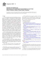
8.5.1 The Photoelectric Nephelometer—(See Fig. 1.) This
instrument uses a light source for illuminating the sample and
a single photo-detector with a readout device to indicate the
intensity of light scattered at 90° to the centerline of the path of
the incident light. The photoelectric nephelometer should be so
designed that minimal stray light reaches the detector in the
absence of turbidity and should be free from significant drift
after a short warm-up period. The light source should be a
Tungsten lamp operated at a color temperature between 2200
and 3000 K. Light Emitting Diodes (LEDs) and laser diodes in
defined wavelengths ranging from 400-900 nm may also be
used. If LEDs or laser diodes are used, then the LED or laser
diode should be coupled with a monitor detection device to
achieve a consistent output. The total distance traversed by
incident light and scattered light within the sample is not to
exceed 10 cm. Angle of light acceptance to the detector:
centered at 90° to the centerline of the incident light path and
not to exceed 610° from the 90° scatter path center line. The
detector must have a spectral response that is sensitive to the
spectral output of the incident light used.
NOTE 1—The pathlength through the sample is shown in red and the shortest scattered light path is in blue. The longer this distance, the better the
measurement sensitivity.
FIG. 1 Technology Diagram of a Nephelometric Non-Ratio Technology
4
D6698 − 14
FIG. 2 Technology Diagram of a Nephelometric Ratio Technology
NOTE 1—The blue traces show the path of the scattered light.
FIG. 3 Diagram of a Multi-Beam Ratio Technology
sensitive to the spectral output of the incident light used. The
instrument calibration (algorithm) must be designed such that
the scalable reading is from the nephelometric detector(s), and
other detectors are used to compensate for instrument variation
described in 3.2.5.
8.5.2.1 Differences in physical design of ratio photoelectric
nephelometers will cause slight differences in measured values
for turbidity even when the same suspension is used for
calibrations. Comparability of measurements made using instruments differing in optical and physical design is not
recommended. Examples of ratio nephelometers are shown in
Figs. 2 and 3.
all reagents shall conform to the specifications of the Committee on Analytical Reagents of the American Chemical Society,
where such specifications are available. Other grades may be
used providing it is first ascertained that the reagent is of
sufficiently high purity to permit its use without lessening the
accuracy of the determination.
NOTE 2—Refer to product MSDS for possible health exposure concerns.
9.2 Standard dilution, reagent and rinse waters shall be
prepared by filtration of Type III water, or better, through a
0.22 microns or smaller membrane or other suitable filter
within 1 hour of use to reduce background turbidity. Reverse
osmosis (RO) water is acceptable and preferred in this test
method. (See Specification D1193.)
8.6 Examples of applicable nephelometers include: photoelectric nephelometer, ratio photoelectric nephelometer with a
single beam design, and ratio photoelectric nephelometer in the
dual beam design. In these designs, the correlation between
detector response and increasing turbidity is positive.
10. Reagents
10.1 Reagent, dilution, and final rinsing water, see 9.2.
9. Purity of Reagents
10.2 Turbidity Standards:
9.1 ACS grade chemicals of high purity (99+ %) shall be
used in all tests. Unless otherwise indicated, it is intended that
NOTE 3—A standard with a turbidity of 1.0 NTU is the lowest formazin
turbidity standard that should be produced on the bench. Preparation of
5
D6698 − 14
NTU stock suspension 25 times to mix (1 second inversion
cycle) and immediately pipetting a volume of the 40.0 NTU
standard (10.2.4). All labware shall be seasoned (see Appendix
X2).
formazin standards shall be performed by skilled laboratory personnel
with experience in quantitative analysis. Close adherence to the instructions within Section 10 is required in order to accurately prepare low-level
turbidity standards.
10.2.1 Equivalent, commercially-available, calibration standards may be used. These standards, such as stabilized formazin and SDVB, have a specified turbidity value and accuracy. Such standards must be referenced (traceable) to
formazin. Follow specific manufacturer’s calibration procedures.
NOTE 5—The instructions below result in the preparation of 200 mL of
formazin standard. Users of this test method will need different volumes
of the standard to meet their instrument’s individual needs; glassware and
reagent volumes shall be adjusted accordingly.
10.2.5.1 Within one day of use, rinse both a glass Class A
5.00 mL pipette and a glass Class A 200-mL volumetric flask
with laboratory glassware detergent or 1:1 hydrochloric acid
solution. Follow with at least ten rinses with rinse water.
10.2.5.2 Using the cleaned glassware, pipette 5.00 mL of
mixed 40.0 NTU formazin suspension (10.2.4) into the 200 mL
flask and dilute to volume with the dilution water. Stopper and
invert 25 times to mix (1 second inversion cycle). The turbidity
of this prepared standard is 1.0 NTU.
10.2.6 Miscellaneous Dilute Formazin Turbidity Suspension
Standard—Prepare all turbidity standards with values below
40.0 NTU daily. All labware shall be seasoned (see Appendix
X2). Standards with values above 40.0 NTU have a useful life
of one week. Use Class A glassware that has been cleaned in
accordance with the instructions in 10.2.5.1 and prepare each
dilution by pipetting the volume of 40 NTU (10.2.4) into a
100-mL volumetric flask and diluting to mark with dilution
water (9.2). For example, prepare so that 50.0 mL of 40 NTU
diluted to 100 mL is 20.0 NTU and 10.0 mL of 40 NTU diluted
to 100 mL is 4.00 NTU.
NOTE 4—All volumetric glassware must be scrupulously clean. The
necessary level of cleanliness can be achieved by performing all of the
following steps: washing glassware with laboratory detergent followed by
3 tap water rinses; then rinse with portions of 1:4 HCl followed by at least
3 tap water rinses; finally, rinse 3 times with rinse water as defined in 9.2.
Reference formazin turbidity standard (4000 NTU) is synthesized on the
bench.
10.2.1.1 Dissolve 5.000 grams of ACS grade hydrazine
sulfate (99.5 % + purity) (N2H4 · H2SO4 into approximately
400 mL of dilution water (see 9.2) contained in a 1-litre Class
A volumetric flask.
10.2.1.2 Dissolve 50.000 grams of ACS grade hexamethylenetetramine (99 %+ purity) in approximately 400 mL of
dilution water (see 9.2) contained in another flask. Filter this
solution through a 0.2-µm filter.
10.2.1.3 Quantitatively pour the filtered hexamethylenetetramine solution into the flask containing the hydrazine sulfate.
Dilute this mixture to 1 litre using dilution water (see 9.2).
Stopper and mix for at least 5 minutes, and no more than 10
minutes.
10.2.1.4 Allow the solution to stand for 24 hours at 25 6
1°C. The 4000 NTU formazin suspension develops during this
time.
10.2.1.5 This suspension, if stored at 20–25°C in amber
polyethylene bottles, is stable for 1 year; it is stable for 1 month
if stored in glass at 20–25°C.
10.2.2 Stabilized formazin turbidity standards are prepared
stable suspensions of the formazin polymer. Preparation is
limited to inverting the container to re-suspend the formazin
polymer. These standards require no dilution and are used as
received from the manufacturer. (See Hach Method 8195 and
U.S. Patent 5,777,011.)
10.2.3 SDVB polymer turbidity standards are prepared
stable suspensions which are used as received from manufacturer or distributor. These standards exhibit calibration performance characteristics that are specific to instrument design.
(See U.S. Patents 4,283,143 and 4,291,980.)
10.2.4 Formazin Turbidity Suspension, Standard (40
NTU)—All labware shall be seasoned (see Appendix X2).
Invert 4000 NTU stock suspension 25 times to mix (1 second
inversion cycle); immediately pipette, using a Class A pipette,
10.00 mL of mixed 4000 NTU stock into a 1000-mL Class A
volumetric flask and dilute with water to mark. The turbidity of
this suspension is defined as 40 NTU. This 40-NTU suspension
must be prepared weekly.
10.2.4.1 This suspension serves as the highest calibration
standard that may be used with this test method.
10.2.5 Dilute Formazin Turbidity Suspension Standard (1.0
NTU)—Prepare this standard dilution daily by inverting the 40
11. Instrument Installation, Sample Lines, and Sampling
NOTE 6—In principle, there are two ways for on-line measurement set
ups: (1) The in-line measurement the sensor is brought directly into the
process (see Fig. 5). (2) The bypass sample technique involves a portion
of sample that is transported via sample lines from the process (source)
and into the measurement apparatus. It is then either transported back to
the process or to waste (see Fig. 6).
11.1 Bypass Sample Technique:
11.1.1 Instrument Installation—Proper location of the sensor and the instrument will help assure accurate results.
Assuring that the sensor sees a flowing, bubble free and
representative sample is essential for accurate results. Refer to
the instrument manufacturer for proper instrument set-up and
installation; also see Practices D3370.
11.1.1.1 Locate the sensor as close to the sample location as
possible to minimize sample response time. Additionally,
locate the instrument for safe, easy access for maintenance and
calibration.
11.1.1.2 Locate the instrument so external interferences
such as vibration, ambient light, humidity, and extreme conditions are minimized.
11.1.1.3 Position the instrument so it is level and stable to
ensure the sample stream is consistent and adequate over long
periods of time.
11.1.2 Sample Lines—Refer to the instrument manufacturer
for recommended sampling procedures for the respective
instrument.
11.1.2.1 Sample inlet lines should be a minimum of 4 mm
inner diameter, rigid or semi-rigid tubing to allow easy passage
of large particles and to minimize the possibility of air lock.
6
D6698 − 14
FIG. 4 Illustration of Proper and Improper Sampling Techniques
FIG. 5 Principle Set-Up for Inline Turbidity Measurement
(1) Refer to the instrument installation procedures from the
manufacturer for optimization of sample flow rates through the
instrument.
11.1.4 The use of either internal or external bubble removal
devices (bubble traps) prior to performing measurement of the
sample is recommended. Reference Practices D3370 and
Guide D3864.
(1) Examples of tubing that can be used for sample lines
include but are not limited to: polyethylene, nylon,
polypropylene, or Teflon9-lined tubing.
(2) Soft or porous tubing that could harbor the growth of
micro-organisms or contribute turbidity to the sample should
not be used.
11.1.3 Sampling:
11.1.3.1 A sample tap should project into the center of the
pipe to minimize interference from air bubbles or pipeline
bottom sediment. See Fig. 4 for proper sample taps or review
instrument manual.
11.1.3.2 Run sample lines directly from the sample point to
the turbidimeter sensor to minimize sample flow lag time
(response time) or refer to instrument manual.
11.1.3.3 Adjust the flow rate to minimize particle fallout in
the sample lines while maximizing bubble removal so bubbles
are not carried through the sensor or refer to instrument
manual.
11.2 In-Line Measurement:
11.2.1 The principle set up for an in-line turbidity measurement is shown below.
11.2.2 For proper set-up and installation of sensor and
transmitter refer to the instrument manufacturer. Some general
recommendations for the installation should be followed:
11.2.2.1 The sensor should be mounted into process lines so
that the sample stream is consistent and adequate to minimize
interference from air bubbles or pipeline bottom sediment.
11.2.2.2 Install sensor surface under an angle with respect to
medium flow so that flow increases self cleaning effects of
optical parts and repels air bubbles.
9
Teflon is a trademark of E.I. du Pont de Nemours and Company, Wilmington,
DE, 19898.
7
D6698 − 14
FIG. 6 The Bypass or Slip-Stream Sample Technique
for up to 30 minutes; standards greater than 40 NTU may
require re-suspension more frequently.
12.2.2 The relationship between turbidity and nephelometric light scatter is known to be linear up to 40 NTU; therefore,
calibration standards ranging up to 40 NTU may be used for
this test method. Verify linearity in the range of interest (or as
close to the measurement range of interest as possible) using
defined calibration or calibration verification standards with a
known accuracy. (Consult manufacturer’s recommendations
for guidance associated with verification methods and devices.)
In case of verification failure, clean the instrument to reduce
stray light levels or contamination. Follow with a recalibration
according to manufacturer’s calibration instructions, or at a
minimum on a quarterly basis.
11.2.2.3 The sensor should be installed with maximized
wall distance to reduce backscattered or reflective signal (see
Fig. 5).
11.2.2.4 Locate transmitter and sensor so that there is easy
access for maintenance or calibration.
11.2.2.5 Adjust the flow rate to minimize particle fallout in
the sample lines while maximizing bubble removal.
11.2.2.6 Measurement should be done under pressure to
avoid degassing.
12. Calibration and Calibration Verification
12.1 Determine if the instrument requires any maintenance
such as cleaning the sample chamber or flow-through cell,
adjusting sample flow rates, etc. Follow the manufacturer’s
instructions for any required instrument maintenance prior to
calibration.
12.3 Verify instrument calibration accuracy in the expected
measurement area using a calibration verification standard. The
calibration verification standard used should have a defined
value with known accuracy. The calibration verification standard should allow the instrument to perform to within its
defined performance specifications. Verification should be
conducted at timely intervals between calibrations. (Consult
manufacturer’s recommendations for guidance associated with
verification methods and devices.)
12.2 Follow the manufacturer’s instructions for calibration
and operation. Calibrate the instrument to assure proper operation for the range of interest with appropriate standards.
NOTE 7—Close adherence to the calibration procedure and to the
rinsing/seasoning techniques is very important to ensure the data remains
consistent across all locations with all of the turbidimeters.
12.2.1 Formazin-based calibration standards should be resuspended through inversion (1 second inversion cycle) 25
times followed by a 2–10 minute wait to allow for bubble
removal. Standards of 40 NTU or below will remain suspended
NOTE 8—Close adherence to the calibration procedure and to the
rinsing/seasoning techniques is very important to ensure the data remains
consistent across all locations with all of the turbidimeters.
8
D6698 − 14
13. Procedure
15. Precision and Bias
13.1 Warm up the instrument according to the manufacturer’s instructions.
13.1.1 Identify the type of technology and the appropriate
reporting unit (see 5.4).
15.1 In Practice D2777, an exemption from the requirement
to conduct a typical interlaboratory study is specifically granted
for test methods involving continuous sampling or
measurement, or both, such as this one. However, results from
independent intra-laboratory studies make the following precision and bias statements possible:
13.2 Verify the flow rate is within the manufacture’s guidelines. If it is not, perform adjustments to the flow to meet these
guidelines.
Turbidity
Standard
13.3 If bubbles are interfering, perform adjustments to
minimize bubbles. These adjustments might include pressurizing the measuring chamber, installing bubble traps and ensuring they are working properly, or changing the flow rate, or a
combination thereof.
0.1 NTU, Inst.
A
0.1 NTU, Inst.
B
4.0 NTU
# of Standards
Analyzed per
Lab
10
2
#
Operators
per Lab
1
Precision
as
%RSD
12
10
2
1
7.3
13
20
1
1
0.9
–0.1
# Labs
Bias,
%
2.9
NOTE 9—Because an interlaboratory study is not possible with on-line
turbidity measurement, the data provided above should be considered only
as examples of the precision and bias that have been achieved using this
test method. Because this test method covers a wide range of turbidity
measuring technologies, the precision and bias characteristics associated
with any specific instrument, compliant with this test method, will also
vary amongst varying technologies. Referencing manufacturers specifications and third party technology verification reports will assist the user of
this test method in better understanding the performance characteristics
that can be expected from a specific instrument.
13.4 Measurement of Water Turbidity:
13.4.1 Determine the frequency of sample data that is being
logged into an appropriate data base. If no data base is to be
used, define the procedure for logging data from the instrument.
13.4.1.1 Data should be logged at defined intervals to
determine when a change to the on-line sample has occurred.
14. Results
14.1 Report results as follows:
16. Keywords
NTU
(or Appropriate Reporting Unit)
Report to Nearest
(NTU or Appropriate
Reporting Unit)
0.01
0.1
<1.00
$1.0
16.1 calibration; calibration verification; continuous; formazin; measurement; monitoring; nephelometer; nephelometric; on-line; standard; styrenedivinylbenzene; turbidimeter;
turbidity; turbidity standards
APPENDIXES
(Nonmandatory Information)
X1. STABILITY OF FORMAZIN
for low-level formazin standards.
X1.1 Stability studies of low level and high level formazin
standards were conducted by ASTM members to support the
formazin preparation instructions set forth in this test method.
X1.1.2 Table X1.2 summarizes the stability data collected
for high-level formazin standards.
X1.1.1 Table X1.1 summarizes the stability data collected
TABLE X1.1 Summary of Low Level Formazin StabilityA
A
NTU
Standard
0.1 Days
1 Day
2.2 Days
0.10
0.30
0.50
20.0
–0.92
–0.74
–1.70
0.00
–1.61
0
–1.70
–0.77
0
3.31
–0.94
–0.51
%Change in the Measured Value Vs Time Since Preparation
7.3 Days
13.1 Days
21 Days
28 Days
–2.99
3.23
–2.21
–2.05
–5.06
–3.23
–6.97
–4.60
–6.70
–5.38
–5.53
–3.07
ASTM Low-Level Formazin Stability Study. ASTM, 100 Barr Harbor Drive, West Conshohocken, PA 19428.
9
–8.05
–6.45
–6.38
–3.07
47 Days
61 Days
81.3 Days
–14.0
–14.8
–8.50
–4.60
–20
–22.9
–11.3
–4.86
–32.4
–44.5
–11.4
–6.39
D6698 − 14
TABLE X1.2 Summary of High Level Formazin StabilityA
Average
Std Dev
% Error vs Theoretical
Day 0.08
19.67
0.5630
–1.650
Day 1.00
19.47
0.5227
–2.650
Formazin 20 NTU
Day 1.92
19.31
0.5250
–3.425
Day 6.92
19.12
0.5766
–4.375
Day 13.92
18.80
0.5891
–5.975
Day 28.79
18.12
0.6034
–9.375
Average
Std Dev
% Error vs Theoretical
Day 0.08
0.610
0.0176
1.091
Day 1.00
0.592
0.0175
–1.267
Formazin 0.60 NTU
Day 1.92
0.591
0.0190
–1.523
Day 6.92
0.586
0.0190
–2.417
Day 13.92
0.569
0.0170
–5.183
Day 28.79
0.533
0.0221
–11.23
A
ASTM High-Level Formazin Stability Study. ASTM, 100 Barr Harbor Drive, West Conshohocken, PA 19428.
X2. PROCEDURE FOR SEASONING GLASSWARE WHEN PREPARING CALIBRATION STANDARDS
X2.1 Introduction
X2.2.2 Rinse a small beaker with a small portion of the
standard. Discard the rinsing to waste. Repeat this a second
time.
X2.1.1 Seasoning is a procedure in which glassware is
conditioned immediately prior use in the preparation of turbidity standards. Seasoning will reduce contamination and volumetric dilution errors and is a common practice in volumetric
quantitative analysis. The process involves rinsing the glassware twice with the specific standard that will be diluted to
prepare a standard of lower value. Seasoning should be used
when preparing any standard from the stock 4000 NTU
formazin standard. It is of primary importance to season pipets
used to prepare low-level turbidity standards. Seasoning should
be performed immediately before performing the actual volumetric dilution. Below is the general procedure that should be
used for seasoning a pipet. A similar practice should be applied
when filling sample cells with sample immediately before
analysis.
X2.2.3 Fill the beaker with enough standard to accommodate at least three times the volume required to prepare the
dilution. For example, if a 10 mL dilution volume is to be used,
then at least 30 mL of standard should be placed in the beaker.
X2.2.4 Draw a small amount of the standard from the
beaker into the pipet. Swirl the standard around the pipet,
making sure it contacts all internal surfaces up to the draw line.
Then, discard this to waste.
X2.2.5 Draw up a second amount of standard from the
beaker up slightly past the fill line. Immediately discard to
waste.
X2.2.6 The pipet is now ready for volumetric draw of the
standard. There should be enough standard left in the beaker to
use. This volumetric draw of the standard should take place
immediately after the seasoning.
X2.2 Procedure
X2.2.1 Prepare the solution that is to be diluted. For
formazin, this involves mixing the standard immediately prior
to use.
X3. SELECTION CRITERIA FLOWCHART FOR TURBIDIMETERS
X3.1 Introduction
X3.2 The technologies listed in this flowchart include many
that may not be suited for low-level process measurements.
However, the chart does serve to provide guidance for selection
of a technology that will be best suited for the sample type and
conditions.
X3.1.1 The criteria was developed as a cooperative effort
between ASTM and the United States Geological Survey.10
10
United States Geological Survey (USGS), “National Field Manual for the
Collection of Water Quality Data,” 12201 Sunrise Valley Drive, Reston, VA, 20192,
.
10
D6698 − 14
FIG. X3.1 Selection Criteria Flowchart for Turbidimeters
ASTM International takes no position respecting the validity of any patent rights asserted in connection with any item mentioned in
this standard. Users of this standard are expressly advised that determination of the validity of any such patent rights, and the risk
of infringement of such rights, are entirely their own responsibility.
This standard is subject to revision at any time by the responsible technical committee and must be reviewed every five years and
if not revised, either reapproved or withdrawn. Your comments are invited either for revision of this standard or for additional standards
and should be addressed to ASTM International Headquarters. Your comments will receive careful consideration at a meeting of the
responsible technical committee, which you may attend. If you feel that your comments have not received a fair hearing you should
make your views known to the ASTM Committee on Standards, at the address shown below.
This standard is copyrighted by ASTM International, 100 Barr Harbor Drive, PO Box C700, West Conshohocken, PA 19428-2959,
United States. Individual reprints (single or multiple copies) of this standard may be obtained by contacting ASTM at the above
address or at 610-832-9585 (phone), 610-832-9555 (fax), or (e-mail); or through the ASTM website
(www.astm.org). Permission rights to photocopy the standard may also be secured from the Copyright Clearance Center, 222
Rosewood Drive, Danvers, MA 01923, Tel: (978) 646-2600; />
11