advanced linux 3d graphics programming
Bạn đang xem bản rút gọn của tài liệu. Xem và tải ngay bản đầy đủ của tài liệu tại đây (14.94 MB, 641 trang )
TEAM LinG - Live, Informative, Non-cost and Genuine!
Advanced
Linux 3D
Graphics
Programming
Norman Lin
Wordware Publishing, Inc.
TEAM LinG - Live, Informative, Non-cost and Genuine!
Library of Congress Cataloging-in-Publication Data
Lin, Norman.
Advanced Linux 3D graphics programming / by Norman Lin.
p. cm.
Includes index.
ISBN 1-55622-853-8 (pbk.)
1. Computer graphics. 2. Linux. 3. Three-dimensional display systems. I. Title.
T385 .L5555 2001
006.6'93 dc21 2001026370
CIP
© 2001, Wordware Publishing, Inc.
All Rights Reserved
2320 Los Rios Boulevard
Plano, Texas 75074
No part of this book may be reproduced in any form or by
any means without permission in writing from
Wordware Publishing, Inc.
Printed in the United States of America
ISBN 1-55622-853-8
10987654321
0106
Blender is a registered trademark of Not a Number B. V.
Other product names mentioned are used for identification purposes only and may be trademarks of their respective companies.
All inquiries for volume purchases of this book should be addressed to Wordware Publishing, Inc., at the above
address. Telephone inquiries may be made by calling:
(972) 423-0090
TEAM LinG - Live, Informative, Non-cost and Genuine!
Contents
Acknowledgments x
Preface xi
Introduction xii
Chapter 1 Basic Linux 3D Graphics Concepts 1
2D Graphics Fundamentals 1
3D Graphics Fundamentals 3
3D Coordinate Systems and Vectors 4
Perspective Projection 5
Matrices 6
Specific Matrix Transformations 6
Other Matrix Properties 7
The l3d Library Classes 8
Sample l3d Program 8
l3d Directory Structure 12
The Five-Step Process of l3d Programs 13
Overview of l3d Classes 19
Applications and Events 19
2D Graphics 20
Concrete Factory Management 24
Specifying Geometry and Behavior 25
Fixed- and Floating-Point Math 29
Summary of l3d Classes 31
Linux Programming Tools 32
Linux 3D Modeling 32
Blender Interface and Commands 33
Exporting and Importing Blender Models 36
Summary 37
Chapter 2 Rendering and Animation Techniques for 3D Polygons 39
Vertex Animation and 3D Morphing 39
Sample Program: morph3d 40
Lighting 48
Mathematical Models for Computing Light 49
Self Lighting 49
Ambient Lighting 50
Diffuse Reflection 50
Specular Reflection 55
Multiple Light Sources and Components 57
Radiosity and Ray Tracing 58
Dynamic or Static Lighting Computations 58
Fog 59
Rendering Techniques for Drawing Light 60
Flat Shading 61
iii
TEAM LinG - Live, Informative, Non-cost and Genuine!
Gouraud Shading 61
Phong Shading 63
Light Maps 63
Texture Mapping 64
Step 1: Define a Texture 65
Storing Texture Data 66
Classes for Loading Textures from Disk 68
Practical Issues in Dealing with Texture Image Files 73
Step 2: Define a Texture Space 74
Step 3: Map Between Texture Space and World Space 76
Calc: A Symbolic Algebra Package 79
Starting and Exiting Calc 79
Stack-Based Computation 80
Entering and Editing Mathematical Entities 82
Solving Systems of Equations 85
Solving the Texture Mapping Equations with Calc 86
Step 4: Reverse Project from Screen Coordinates into Texture Coordinates 89
Step 5: Map Texture Coordinates to Integer Indices and Draw 92
An Optimized Texture Mapping Strategy: u/z, v/z, 1/z 93
The Division Operation and Texture Mapping 95
Associating Textures with 3D Polygons 96
Rasterization Classes for 3D Polygons 98
An Abstract 3D Rasterizer: l3d_rasterizer_3d 98
A Software 3D Rasterizer Implementation: l3d_rasterizer_3d_sw_imp 101
A Mesa/OpenGL 3D Rasterizer Implementation: l3d_rasterizer_3d_mesa_imp 115
Sample Program: textest 129
Light Mapping Revisited 135
Software Light Mapping 136
Surfaces 136
Surface Cache 141
Light Mapped Polygons 142
Software Rasterization of Light Maps 147
Hardware Light Mapping 147
Sample Program: lightmap 151
Shadows and Light Maps 159
Summary 160
Chapter 3 3D Modeling with Blender 161
Tutorial: Creating and Exporting Compatible, Textured 3D Morph Targets 161
The Starting Morph Mesh 162
Inserting Two Morph Targets into Blender 163
Deforming the Mesh 165
Applying a Texture and Assigning Texture Coordinates 167
Testing the Morph in Blender 173
Exporting the Two Morph Targets 173
Exporting the Texture Information 174
Importing the Morph Targets into a Program 175
Tutorial: Using Inverse Kinematics and Roto- scoping to Model a
Walking Human Figure 180
Inverse Kinematics: Definition 181
Creating an Ika Chain in Blender 183
iv Contents
TEAM LinG - Live, Informative, Non-cost and Genuine!
Working with Ika Chains 183
Creating the Arm Ikas 184
Creating the Main Body Ika 185
Parenting the Ikas into a Hierarchy 185
Testing the Ika Chains 187
Animating the Ika Chains 188
Connecting Ika Chains and Meshes 189
Texturing and Exporting the Model 190
Importing the Textured Ika Meshes 192
Rotoscoping and Inverse Kinematics 197
Programming IK and FK 200
Summary 201
Chapter 4 Visible Surface Determination I: General Techniques 203
The Goals of VSD 204
Back-Face Culling 207
3D Convexity and Back-Face Culling 209
Sample Program: backface 209
Class l3d_World_Backface 214
View Frustum Culling 218
Defining a View Frustum 218
Computing the Frustum in World Coordinates 220
Class l3d_Viewing_Frustum 221
Using the Frustum Planes 223
Hierarchical View Frustum Culling 223
Bounding Spheres and the View Frustum 225
Computing Bounding Spheres 227
Class l3d_bounding_sphere 228
Other Bounding Volumes 231
Clipping Against the View Frustum 233
Sample Program: frustum 233
Class l3d_World_Frustum 236
The Painter’s Algorithm 242
The Z Buffer Algorithm 245
General Observations about the Z Buffer 246
A Software Z Buffer: Class l3d_rasterizer_3d_zbuf_sw_imp 248
Mesa/OpenGL Z Buffering 257
Factory Manager for Z Buffered Rasterizers 261
Sample Program: texzbuf 263
Z Buffer-like Algorithms 264
Summary 266
Chapter 5 Visible Surface Determination II:
Space-partitioning Techniques 267
Binary Space Partitioning Trees, Octrees, and Regular Spatial Partitioning 267
Using a BSP Tree to Partially Pre-sort Polygons 271
Choosing a Splitting Plane 272
Back-to-Front Rendering (Painter’s Algorithm Revisited) 274
Front-to-Back Rendering 275
Combining BSP Trees and Bounding Volumes 275
Sample Program: bsp 276
Contents v
TEAM LinG - Live, Informative, Non-cost and Genuine!
Classes l3d_halfspace and l3d_bsptree 277
Class l3d_world_bsptree 286
The Main Program 290
The World Database, Revisited 293
Leafy BSP Trees: Automatic Convex Partitioning of Space 293
Creating a Leafy BSP Tree 295
Methods for Leafy BSP Trees in Class l3d_bsptree 296
Sample Program: leafybsp 297
Axis-aligned BSP Trees and Mini BSP Trees 302
BSP Tree as a Multi-resolution Solid-Modeling Representation 303
BSP Trees and Dimension Independence 306
Octrees 306
Regular Spatial Partitioning 308
Portals and Cells 308
The Main Ideas Behind the Portal Algorithm 308
Rendering a Portal World 310
Observations about the Portal Scheme 313
Portals as a Connectivity Graph 313
Advantages and Disadvantages 313
Back-Face Culling 314
Clipping 314
Convexity or Non-Convexity 315
Moving the Camera and Objects Within a Portal Environment 315
Portals and the Near Z Plane 316
Shadows 318
Mirrors 320
Portals and Other Rendering Methods 321
Classes for Portals and Sectors 322
Class l3d_polygon_3d_portal 322
Class l3d_sector 323
Class l3d_world_portal_textured_lightmapped_obj 329
Class l3d_rasterizer_2d_sw_lighter_imp 344
Class l3d_pipeline_world_lightmapped 351
Sample Program: porlotex 353
Other VSD Algorithms 356
Summary 357
Chapter 6 Blender and World Editing 359
World Editing 360
No World Editor 360
Write Your Own World Editor 361
Adapt an Existing Editor 362
Using Blender for Portal Worlds 363
Main Ideas of a Blender Portal World Editor 364
Step-by-Step Guide to World Design 367
Data Flow within the World Editing System 368
Creating Sectors and Portals 369
Tutorial: Creating Aligned Portals via Extrusion and Separation 371
Tutorial: Aligning Portals from Separate Meshes 374
Tips for Working with Portals 382
Portalization: Generating Portal Connectivity 385
vi Contents
TEAM LinG - Live, Informative, Non-cost and Genuine!
Perl Scripts 387
Architecture of the Perl Portalization System 389
Structural Modules 390
Parsing and Generator Modules 415
Controlling Scripts 429
Embedding Location, Orientation, Texture, Actor, and Other Information into Meshes 430
Basic Ideas of Associating Attributes with Objects 431
Store an ID, Location, and Orientation in Overlapping Edges 431
The Tool Blend_at: Remote Control of Blender 433
Configuration and Testing of blend_at 434
Specific Mesh Attributes Used by the Portalization System 437
The Name Attribute 437
The Type Attribute 437
Attributes for Sectors 437
Attributes for Actors 439
Parsing of Attributes by VidscParser.pm and vidinfo 440
Program Listings for blend_at 446
Class vertex 447
Class blender_config 447
Class blender_controller 448
Class blender_xcontroller 449
Tutorial: Creating a Textured Room with Actors 463
Tips for Working with Attributes 473
Summary of Blender and Portal Worlds 474
Other World Editing Ideas 475
Portalized Regular Spatial Partitioning 475
BSP Tree and Octree 476
Non-convex Sector-based Partitioning 476
Summary 478
Chapter 7 Additional Graphics Techniques 479
Special Effects 479
Environment Mapping 480
Billboards 484
Lens Flare 486
Particle Systems 487
Physics and Particle Systems 488
Real-Time Update 489
Sample Program: particle 490
Comments on the Sample Program’s Physics 496
Some Ideas for You to Try 496
Natural Phenomena 497
Bump Mapping 499
Multi-pass Techniques 500
Advanced Techniques 501
Curved Surfaces 501
Level of Detail 505
Billboards 506
Edge Collapse 506
BSPTree 507
Texture LOD Techniques: MIP Mapping 508
Contents vii
TEAM LinG - Live, Informative, Non-cost and Genuine!
Landscapes 509
Storing Landscapes as Height Fields 509
Generating Fractal Landscapes 510
Rendering and LOD Techniques for Landscapes 511
Camera Tracking 512
Summary 513
Chapter 8 Non-Graphical Techniques for Games and
Interactive Environments 515
Sound 515
Basics of Digital Sound 516
The RPlay Server 519
Using TCP/IP Networking to Communicate with the Server 520
Class l3d_sound_client 521
Class l3d_sound_server_rplay 522
TCP/IP Networking 524
The Client 524
The Server 526
Running the Sample Server and Client 529
Non-Blocking Operations 529
What Data to Send 530
Collision Detection 530
Intersection Testing and Bounding Volumes 531
Sphere-to-Sphere 532
Ray-to-Polygon 532
Ray-to-Sphere 535
Sphere-to-Polygon 536
Tunneling and Sweep Tests 538
Multiple Simultaneous Collisions and Collision Response 541
Allowing Penetration 541
Avoiding Penetration with Temporal Search 542
Class l3d_collidable 543
Class l3d_collidable_sphere 544
Class l3d_polygon_3d_collidable 548
Class l3d_polygon_3d_textured_lightmapped_collidable 551
Class l3d_camera_collidable 552
Class l3d_world_portal_textured_lightmapped_obj_colldet 553
Plug-in Object Seeker, Class l3d_plugin_videoscape_mesh_seeker 563
Sample Program: collide 574
More Advanced Collision Detection and Response 576
Physics 577
Some Basic Concepts 577
Rigid Body Dynamics 578
Real-Time Update and Numerical Integration 579
Artificial Intelligence 580
Summary 582
Chapter 9 What Lies Ahead? 583
Content Development Systems 583
Game Blender/Blender 2.0 583
World Foundry 590
viii Contents
TEAM LinG - Live, Informative, Non-cost and Genuine!
What Does This Mean for 3D Programmers? 598
The Future 599
Summary 600
Perspective 600
Appendix 603
CD Installation 603
License 603
Contents of the CD-ROM 603
Quick Start Guide 604
Directories 604
Installing the Sample Programs and Other Software 605
Troubleshooting the Sample Programs 607
Some Comments on the Sample Programs 607
Hardware Acceleration 608
Porting the Code to Microsoft Windows 609
Tools Used to Prepare this Book 610
Resources 611
3D Graphics Programming 612
3D Modeling 612
3D Information and Applications 613
General Programming 613
Other 614
References 614
Index 617
Contents ix
TEAM LinG - Live, Informative, Non-cost and Genuine!
Acknowledgments
I
n addition to my parents, Forest and Vicki Lin, I would like to thank the following individuals
who directly or indirectly played a role in the completion of this book. Thanks go to my brother
Tony, who persuaded me to download and try out the game Doom—an experience that con-
vinced me that interactive 3D graphics on the PC was finally possible. Special thanks also to Stan
Hall, who provided encouragement and advice even when it seemed that the book might not see
the light of day.
Solveig Haring and Margit Franz were kind enough to provide me with Internet access and a
cup of coffee for some of the longer nights in the computer lab. Ton Roosendaal provided some
very interesting insights into Blender and 3D graphics in general. My work colleagues Horst
Hörtner, Werner Pankart, Klaus Starl, and Thomas Wieser were all supportive and understanding
during those times when work on the book required absence from the office. Andreas Jalsovec and
Dietmar Offenhuber gave me insight into some of the nuances of 3D modeling. Renate Eckmayr,
Viju John, Azita Ghassemi, Manfred Grassegger, Ulrike Gratzer, Andrea Groisböck, Jogi and
Reni Hofmueller, Angelika Kehrer, Astrid Kirchner, Dietmar Lampert, Christine Maitz, Paula
McCaslin, Bernd Oswald, Gabi Raming, Regina Webhofer, and other individuals too numerous to
mention all expressed interest upon hearing that I was writing this book, and gave me much
needed inspiration and motivation.
Professor Deborah Trytten got me started on the right track in 3D graphics during my studies
at the University of Oklahoma. Kevin Seghetti carefully read and checked the text for technical
accuracy and provided many valuable suggestions. Thanks also to everyone at Wordware Pub-
lishing, especially Jim Hill, who shared my enthusiasm about the book and was key in actually
getting this project out the door.
Last but not least, I would like to thank the countless individuals around the world involved
with the creation and maintenance of the freely available, high quality, open source GNU/Linux
operating system and tools.
x
TEAM LinG - Live, Informative, Non-cost and Genuine!
Preface
A
university professor of mine once mentioned that there was no danger that the computer
science community would ever run out of interesting problems to solve. As a community,
computer scientists try to understand the nature of computation by forming theories and
attempting to prove their validity. We try to answer questions. Those theories which correctly cap-
ture the nature of computing problems contribute to the common pool of academic knowledge.
Previously unanswered questions receive answers—some more complete, some less complete.
The less complete answers raise new questions for further research; the more complete answers
are eventually adopted by industry practitioners.
3D graphics is a field that illustrates this phenomenon well. In the early days, 3D graphics was
mostly confined to academic research labs. The mathematics and geometry of 3D graphics were
questioned and explored, and the field grew as a result. Today, research in 3D graphics is still very
active, but at the same time, 3D graphics has also become mainstream. A number of graphics tech-
niques from academia have established themselves as efficient and effective enough for
widespread use. A 3D programmer should be familiar with these techniques. The purpose of this
book is to communicate these important 3D techniques to the intermediate 3D programmer in a
clear and intuitive way, using geometrical explanations supported with numerous working code
examples.
This book uses Linux as the implementation platform. The free operating system has a num-
ber of advantages which make it ideal for learning and programming 3D graphics. The most
important advantage is accessibility: the free, open source nature of Linux makes it possible for
any programmer to have access to a top-quality operating system and development environment.
This open nature has encouraged the development of massive amounts of free software (where
free refers not only to cost, but mainly to the freedom to study and modify the source code), includ-
ing software important for 3D graphics. Therefore, Linux offers any programmer the chance to get
involved with 3D graphics programming today, at no cost, without forcing the programmer to
either pay thousands of dollars in software licensing fees or to spend literally man-years of soft-
ware development time creating customized tools. Linux already offers the tools you need to do
serious 3D programming—and the freedom to use, learn from, and modify these tools.
This book builds upon the foundation laid in the introductory companion volume Linux 3D
Graphics Programming. It is assumed that you have an understanding of all of the material pre-
sented in the introductory volume; the first chapter provides a quick review of this material.
Therefore, this book is not suited for the complete beginner to 3D graphics. Such readers should
work through the introductory companion book before attempting to read this book.
xi
TEAM LinG - Live, Informative, Non-cost and Genuine!
Introduction
W
elcome, reader! I am glad to have you along and hope that you are as excited as I am
about Linux and interactive 3D graphics programming. Take your time and enjoy the
following few pages as we leisurely discuss the goals and contents of this book.
This book is the second volume of a two-volume work on interactive 3D graphics program-
ming under Linux. First, let’s look at the two-volume work as a whole, then we’ll look more
specifically at the contents of this volume.
Taken as a whole, the two-volume work aims to provide you with the knowledge, code, and
tools to program top-notch, object-oriented, real-time 3D games and interactive graphics applica-
tions for Linux, which can also easily be ported to other platforms. By working through both
volumes, you will learn to use the most important techniques, tools, and libraries for Linux 3D
graphics: portals, OpenGL/Mesa, Xlib, 3D hardware acceleration, collision detection, shadows,
object-oriented techniques, and more. We also cover the often neglected topic of 3D modeling,
illustrating in detail how to use the professional 3D modeling package Blender, which is included
on the CD-ROM, to create animated 3D models and portal worlds for use in our interactive 3D
programs.
This second volume, titled Advanced Linux 3D Graphics Programming, covers more
advanced techniques needed for realistic display of larger datasets often used in interactive 3D
environments. Topics covered include: rendering and animation techniques for 3D polygons (3D
morphing, texture mapping, light mapping, fog), the creation of more sophisticated 3D models
with Blender (including jointed figures animated with inverse kinematics), importing such models
from Blender into our programs, hidden surface removal (portals, BSP trees, octrees, z buffers),
non-graphical issues relevant to interactive environments (special effects, collision detection, dig-
ital sound, TCP/IP networking, particle systems), and tutorials on using advanced 3D content
development systems under Linux (Game Blender and World Foundry). Sample programs are
provided, both in text form and on the CD-ROM, illustrating the concepts.
This book builds on the foundation laid by the introductory companion volume, Linux 3D
Graphics Programming. The first chapter of this book serves as a brief review of the earlier
material.
Goals of This Text
This text has several objectives. A primary goal of this text is to give you a solid understanding of
the fundamental concepts involved in interactive 3D graphics programming at the intermediate to
advanced level. Such an understanding not only enables you to write your own 3D programs,
libraries, and games under Linux, but also gives you the knowledge and confidence you need to
xii
TEAM LinG - Live, Informative, Non-cost and Genuine!
analyze and use other 3D graphics texts and programs. In the open source world of Linux, under-
standing fundamental concepts is indeed important so that you can understand and possibly
contribute to the common pool of knowledge and code. Furthermore, learning fundamental 3D
graphics concepts also enables you to understand and effectively use sophisticated 3D applica-
tions and libraries such as 3D modelers and OpenGL.
A second goal of this text is to give you plenty of hands-on experience programming 3D
graphics applications under Linux. It is one thing to understand the theoretical mechanics of an
algorithm; it is another to actually implement, debug, and optimize that same algorithm using a
particular set of programming tools. Small standalone programs are scattered throughout this text
to demonstrate key 3D graphics concepts. It is often easy to lose sight of the forest for the trees,
particularly in the complicated world of 3D graphics. Standalone sample programs address this
problem by concisely illustrating how all the necessary components of a 3D program “fit
together.” They reduce the intimidation that often accompanies the study of large, complicated
programs, and give you confidence in developing and modifying complete 3D programs under
Linux.
A third goal of this text is to help you develop and understand the techniques for developing a
reusable 3D application framework or library. In addition to the standalone programs mentioned
above, the book also develops a series of generally reusable C++ library classes for 3D graphics,
called the l3d library. This library was introduced in the introductory companion book Linux 3D
Graphics Programming and is developed further in this book. This C++ library code follows an
object-oriented approach, relying heavily on virtual functions, (multiple) inheritance, and design
patterns. In this manner, the developed library classes are usable as is but still open for extension
through subclassing. Each chapter builds upon the library classes developed in previous chapters,
either adding new classes or combining existing classes in new ways. Through subclassing, the
library classes can be adapted to work with virtually any hardware or software platform or API;
currently, the code runs under Linux and Microsoft Windows, with or without hardware accelera-
tion. The techniques used to develop the 3D library classes illustrate both valuable 3D abstractions
and generally applicable object-oriented techniques.
A fourth goal of this text is to demonstrate the excellence of the Linux platform as a graphics
programming environment. For a programmer, Linux is a dream come true. All of the source code
is available, all of the operating system features are enabled, a large number of excellent first-rate
software development tools exist, and it is all freely available, being constantly tested and
improved by thousands of programmers around the world. Linux empowers the programmer with
open source, open information, and open standards. Given this outstanding basis for development,
it is no wonder that programmers in every conceivable application area (including 3D graphics)
have flocked to Linux. This has created a wealth of 3D libraries, tools, and applications for Linux.
Linux is, therefore, an outstanding software development platform with powerful 3D tools and
software—an ideal environment for learning and practicing 3D graphics programming.
A final, personal goal of this text, and the main reason I am writing this book, is to impart to
you a sense of the excitement that 3D graphics programming offers. You, the 3D programmer,
have the power to model reality. You control every single z-buffered, Gourad-shaded, tex-
ture-mapped, perspective-correct, dynamically morphed, 24-bit, real-time pixel on the flat 2D
screen, and amazingly, your painstakingly coded bits and bytes merge to form a believable 3D
Introduction xiii
TEAM LinG - Live, Informative, Non-cost and Genuine!
world. By working under Linux, you are no longer held back by a lack of tools or software. It’s all
out there—free for download and top quality. Linux software gives you the tools you need to real-
ize your 3D ideas.
Organization of the Book and the Code
This text follows a bottom-up organization for the presentation order of both concepts and pro-
gram code. This bottom-up organization serves two purposes: pedagogical and practical.
Seen pedagogically, a bottom-up approach means first covering fundamental concepts before
proceeding to more complex subjects. This is a fully natural progression which deals with com-
puter graphics at ever-increasing levels of abstraction. Seen practically, a bottom-up approach
means that simple C++ classes are developed first, with later, more complicated examples literally
“building upon” the foundation developed earlier through the object-oriented mechanism of
inheritance. This ensures compilable, executable code at each level of abstraction which is
incrementally understandable and extensible. Every chapter has complete, executable sample pro-
grams illustrating the concepts presented.
The bottom-up organization has a rather far-reaching impact on the structure of the code in
general. The principal goal I had in mind when structuring the code for the book was that all parts
of a class presented in a chapter should be explained within that same chapter. I tried very dili-
gently to achieve a code structure which allows me to avoid statements like “ignore this part of the
code for now; it will be explained in the next chapter.” When a class is presented, you should be
able to understand it fully within the context of the current chapter. The second most important
goal for the code was to reuse as much code as possible from previous chapters, typically through
subclassing, thus truly illustrating how more complex 3D concepts literally, at the code level,
build upon simpler concepts. To achieve these goals, the overall design of the code relies heavily
on indirection through virtual functions, even in fairly time-critical low-level routines such as
accessing elements of a list. The presence of so many virtual functions allows for a rather clean,
step-by-step, bottom-up, incrementally understandable presentation of the code. The design is
also very flexible; new concepts can be implemented through new subclasses, and behavior can be
swapped out at run time by plugging in new concrete classes. But as is always the case in computer
science, there is a tradeoff between flexibility and performance. The code design chosen for the
book is not as fast as it could be if all the virtual function calls were eliminated; of course, elimi-
nating virtual function calls leads to reduced flexibility and increased difficulty extending the
code later. Still, the code performs well: it achieves over 30 frames per second with software ren-
dering on a Pentium II 366 in a 320´ 240 window with 24-bit color, and over 30 frames per second
in 1024´ 768 with Voodoo3 hardware acceleration. In spite of its definite educational slant, it is
fast enough for real use. Again, this is one of the great things about 3D programming in the 21st
century: a straightforward, educationally biased code structure can still be executed fast enough
by consumer hardware for real-time, interactive 3D environments. Real-time 3D no longer forces
you to wrestle with assembly or to have access to expensive dedicated graphics workstations. If
you know how to program in C++ and you understand the geometrical concepts behind 3D graph-
ics, you can program real-time 3D graphics applications using free tools under Linux.
xiv Introduction
TEAM LinG - Live, Informative, Non-cost and Genuine!
Let’s now look at the organization of the text itself.
Chapter 1 reviews the essentials of Linux 3D graphics, as covered in the introductory com-
panion volume Linux 3D Graphics Programming. We cover the fundamentals of 2D graphics, 3D
coordinate systems, perspective projection, vectors, matrices, and the C++ library classes—the
l3d library—used to implement these basic ideas. We also review the most important commands
for the 3D modeling package Blender. The information in this chapter is a prerequisite for under-
standing the rest of the book.
Chapter 2 explores some important techniques which greatly increase the visual realism of
polygonal models: texture mapping, lighting, light mapping, and morphing. All of these tech-
niques are implemented in C++ classes. We also take a tour of the symbolic algebra package Calc,
available as an extension to the Emacs editor. Calc helps us solve the tedious sets of equations
which arise when performing texture mapping.
Chapter 3 is the first of two chapters dealing with Blender, a free and powerful 3D modeling
and animation package for Linux (included on the CD-ROM). In two step-by-step tutorials, we
walk through the creation of a set of textured and compatible morph targets suitable for 3D
morphing, and a human-like figure animated with inverse kinematics. These 3D models are then
imported and displayed in a 3D program.
Chapter 4 deals with the correct and efficient drawing of visible surfaces, which becomes
especially important when polygon counts increase. Surfaces which are obscured by other sur-
faces or which are completely outside of the field of vision should be discarded from unnecessary
processing as early and as cheaply as possible. We discuss a number of generally applicable tech-
niques, each illustrated with a sample program: back-face culling, the painter’s algorithm, view
volume culling, and z-buffering.
Chapter 5 discusses special visible-surface algorithms based on space-partitioning tech-
niques. The techniques discussed include BSP trees, octrees, regular spatial partitioning, and
portals. We discuss the use of portals for special techniques such as mirrors, refraction, transpar-
ency, and volumetric shadows. A portal engine is implemented as a natural extension of the
existing polygon and object classes.
Chapter 6 continues the discussion of portals from a practical point of view. We explore how
we can use Blender’s powerful modeling features to create portal-based worlds, using a combina-
tion of an edge-coding technique, to encode arbitrary data within a 3D mesh, and postprocessing
scripts written in the Perl language. This system, using both Blender and custom-written tools,
allows us to create 3D worlds which may be used by the portal engine developed in the previous
chapter. A complete example world is constructed step by step, with practical tips on efficiently
working in Blender: using layers, hiding geometry, aligning objects and portals, and executing
interactive fly-throughs.
Chapter 7 covers some special 3D graphics techniques or “tricks”: billboards, lens flare, parti-
cle systems, fractal landscapes, dynamic level-of-detail, environment mapping, atmospheric
effects, curved surfaces, multi-pass techniques, and camera tracking in 3D.
Chapter 8 discusses non-graphical techniques that can greatly enhance the reality of 3D
graphics programs, such as games. Techniques discussed and implemented include: collision
detection, digital sound and music with the RPlay sound server, TCP/IP network communications,
physics, and artificial intelligence.
Introduction xv
TEAM LinG - Live, Informative, Non-cost and Genuine!
Chapter 9 takes a look at the possible future direction of Linux and 3D graphics. We begin
with a look at two existing and exciting 3D content development systems under Linux: Game
Blender and World Foundry. We go through a brief tutorial of 3D game creation with each of these
systems. Some speculation about the future of Linux 3D graphics follows. We close by relating the
contents of the book to the field of 3D graphics as a whole.
The Appendix provides installation instructions for the CD-ROM, information on porting the
graphics code to Windows, and a list of useful references, both in electronic (WWW) and in print
form. Notations in brackets, such as [MEYE97], are detailed in the “References” section of the
Appendix.
The CD-ROM contains all sample code from the book, the Blender 3D modeling and anima-
tion suite, the World Foundry game development kit, freely available Linux 3D libraries and
applications, and a series of animated videos illustrating some of the more difficult-to-visualize
3D concepts discussed in the text.
Reader and System Requirements
This book requires you to have a working Linux installation up and running with the XFree86
server for the X Window System on an IBM PC or compatible system with a Pentium or better
processor. If you don’t yet have Linux installed, you can download Linux for free from the
Internet, or obtain a CD-ROM containing a ready-to-install Linux distribution. Installing Linux is
no more difficult than installing other common PC operating systems, such as Microsoft Win-
dows. A 3D graphics card with Mesa drivers is recommended for optimum performance, but the
code will run acceptably fast without hardware acceleration through a custom software renderer.
If your graphics card is supported by the new XFree86 4.0 Direct Rendering Infrastructure or by
the Utah GLX project, you can also link the code with the appropriate OpenGL library (from the
DRI or from Utah GLX) to achieve hardware-accelerated rendering in a window.
Typographical Conventions
Used in This Book
The following typographical conventions are used in this book.
n
Program code, class names, variable names, function names, filenames, and any other text
identifiers referenced by program code or the operating system are printed in a fixed-
width font.
n
Commands or text to be typed in exactly as shown are printed in boldface.
n
Key sequences connected by a plus (+) sign (such as Ctrl+C) mean to hold the first key while
typing the second key.
xvi Introduction
TEAM LinG - Live, Informative, Non-cost and Genuine!
Chapter 1
Basic Linux 3DBasic Linux 3D
Graphics ConceptsGraphics Concepts
L
inux 3D graphics is a young and exciting field. The purpose of this chapter is to review the
basic concepts of Linux 3D graphics programming in order to lay a groundwork for the more
involved material in the following chapters. This book was written based on the assumption
that you already know everything in this chapter; therefore, this chapter is intentionally terse. This
chapter is meant to serve as a review, not as an introduction.
If you find some of these topics unfamiliar, I suggest that you take the time to read the com-
panion volume to this book, Linux 3D Graphics Programming. The companion book is aimed at
the beginning 3D graphics programmer with little or no 3D experience. Essentially, this chapter is
a brief review of the most important concepts in the introductory companion volume.
2D Graphics Fundamentals
2D raster graphics consist of plotted pixels on a display. The pixels are arranged in a rectangular
grid, typically accessible in memory as a linear sequence of bytes. Though we specify pixels by
their addresses in memory at the lowest level, it is better to specify pixels in terms of a 2D coordi-
nate system, with horizontal x and vertical y axes. In this book, we define the origin of the 2D pixel
coordinate system to be the upper-left corner of the screen, with the x axis increasing to the right
and the y axis increasing downward.
Under Linux, we display our graphics under the X Window System. Specifically, the
approach chosen for this book is to use XImages in ZPixmap format to display 2D graphics. This
allows us direct access to the bytes (and thus the pixels) forming the image. Each pixel can have a
particular color. Exactly how this color is specified depends on the bit depth and color model of the
X server. The bit depth determines the total number of available colors and is usually 8, 15, 16, 24,
or 32 bits. The color model is typically either indexed color (meaning that colors are specified as
indices into a fixed-size palette of colors) or true color (meaning that colors are specified directly
as a combination of red, green, blue, and possibly alpha intensities). For maximum flexibility, we
must query at run time the bit depth and color model, and dynamically determine the exact bit for-
mat required to specify pixel colors.
1
TEAM LinG - Live, Informative, Non-cost and Genuine!
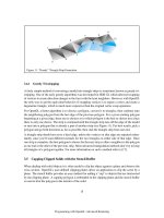
Drawing lines can be done by an incremental algorithm, stepping along one axis by whole
pixels and using the line’s slope to determine how many pixels to step in the other axis. Drawing
polygons can be done by rasterizing the lines belonging to the left and right edges of the polygon,
and drawing horizontal lines, or spans, between the left and right edges.
Animation can be achieved through double buffering. With this technique, we have one
off-screen buffer and one on-screen buffer. We draw graphics in the off-screen buffer. When we
are finished, we copy the off-screen buffer into the on-screen buffer, at which point the graphics
become visible. Then, we draw the next frame of animation in the off-screen buffer, and repeat the
process. In this way, the on-screen buffer is continually updated with new and completed images
from the off-screen buffer, thus creating the illusion of animation.
Hardware acceleration allows us to send compact instructions to dedicated hardware, with
higher-level commands such as “draw a line” or “draw a polygon.” By sending such higher-level
commands to the hardware, and by letting the dedicated hardware then do the actual lower-level
pixel operations, a great speed-up can be achieved. Under Linux, we use the 3D library Mesa to
achieve hardware acceleration. Mesa has a syntax essentially identical to OpenGL and supports
hardware acceleration. The XFree86 4.0 project uses Mesa as part of its Direct Rendering Infra-
structure (DRI), providing for hardware-accelerated 3D graphics within a window under the X
Window System. We use the terms Mesa and OpenGL essentially interchangeably in this book.
2 Chapter 1: Basic Linux 3D Graphics Concepts
Figure 1-1: Drawing a 2D polygon.
TEAM LinG - Live, Informative, Non-cost and Genuine!
3D Graphics Fundamentals
3D graphics is the creation of a two-dimensional image or series of images on a flat computer
screen such that the visual interpretation of the image or series of images is that of a three-dimen-
sional image or series of images.
The visual interpretation of an image depends on the optics of light rays striking the retina.
Points emit light radially in all directions along straight lines, called light rays. Some subset of all
light rays enters the eye; we call this subset seen light rays. Seen light rays are refracted by the
eye’s lens, and focus onto the retina. The biochemical reactions within the retina produce the sen-
sation of vision.
If a 2D image causes the same light rays to strike the retina as those coming from a 3D object,
then the 2D image can be interpreted as a 3D object.
In 3D graphics, we want the seen light rays coming from the flat computer screen to corre-
spond to the seen light rays which would be seen if we were looking at a real 3D object located
behind the computer screen. To accomplish this, we compute intersections between the seen light
rays and the flat plane of the computer screen. These intersection points, since they lie along the
straight light rays going from the original 3D points to the eye, emit the same seen light rays as the
Chapter 1: Basic Linux 3D Graphics Concepts
3
Figure 1-3: Light
rays.
Figure 1-2: Definition of 3D
graphics.
TEAM LinG - Live, Informative, Non-cost and Genuine!
original points. Therefore, the projected points can be visually interpreted to be the original 3D
object.
Computing an intersection between a seen light ray (coming from a point) and a flat plane is
called projecting the point onto the plane. In particular, this is a planar geometric perspective pro-
jection. The important term is “perspective.” The fact that the projection is perspective implies
that the resulting images appear realistically foreshortened, just as would be perceived by our own
eyes or by a physical camera taking a 2D snapshot of a 3D scene.
3D Coordinate Systems and Vectors
Before we can perform a perspective projection on points, we need a coordinate system to specify
the points in 3D. We can use a left-handed or a right-handed coordinate system. Define a coordi-
nate system such that x´ y=z, where the symbol ´ represents the vector cross product. In a
right-handed system, the vector cross product is computed using the right-handed convention,
implying that in Figure 1-5, the z axis points out of the page. In a left-handed system, the vector
cross product is computed using the left-handed convention, implying that in Figure 1-6, the z axis
points into the page.
In this book, we use the left-handed coordinate system, and the left-handed convention for
computing our vector cross products. By using both a left-handed coordinate system and a
left-handed rule for computing cross products, the results we obtain and the equations we use are
identical to those which would be used with a right-handed coordinate system and a right-handed
rule for computing cross products.
Within a coordinate system, we can specify points and vectors. Points are locations in the
coordinate space; vectors are directed displacements between points in the coordinate space. Be
careful not to confuse points and vectors. One way to specify points and vectors is to use the nota-
tion (x,y,z). (Another way is homogeneous notation; see the next section.) In this notation, the
point (x,y,z) is the point located at a distance of x units from the origin along the x axis, y units from
the origin along the y axis, and z units from the origin along the z axis. On the other hand, the vec-
tor (x,y,z) specifies the displacement of x units along the x axis, y units along the y axis, and z units
along the z axis. Since it is a directed displacement, we can add the vector (x,y,z) to any point to
arrive at a new, displaced point.
4 Chapter 1: Basic Linux 3D Graphics Concepts
Figure 1-4: A 2D image can be interpreted as a 3D
object.
TEAM LinG - Live, Informative, Non-cost and Genuine!
A number of standard operations are defined on vectors. Important for this book are compo-
nent-wise vector addition, scalar-vector multiplication, the vector dot product, and the vector
cross product.
Perspective Projection
Given a coordinate system in which to specify (x,y,z) points, we can then apply a perspective pro-
jection to these points to obtain the projected points, for which the seen light rays are identical to
those of the original non-projected points. In its simplest form, the perspective projection of a
point (x,y,z) is:
This formula is derived by computing the intersection between the seen light ray, coming from the
point, and a flat 2D projection plane. The d term is essentially a scaling factor. A more complete
formulation of the perspective projection is:
This form of the equation explicitly specifies the use of the d term as a field of view angle theta.
Also, it reverses the y axis orientation because it maps the projected points to the 2D pixel
Chapter 1: Basic Linux 3D Graphics Concepts
5
Equation 1-4
Equation 1-3
Equation 1-5
Equation 1-6
Equation 1-2
Equation 1-1
Figure 1-5:
Right-handed
3D coordinate
system.
Figure 1-6:
Left-handed 3D
coordinate
system.
TEAM LinG - Live, Informative, Non-cost and Genuine!
coordinate system. As we have seen, the 2D pixel coordinate system has y increasing downwards,
while the 3D coordinate system has y increasing upwards.
Matrices
In this book, we use 4´ 4 matrices to effect transformations on points. We can also then use 4´ 1
column vectors to represent 3D points and 3D vectors. Do not confuse the terms “column vector”
and “3D vector.” The former refers to a notational convention; the latter, to a directed displace-
ment in 3D space. The latter can be expressed by using the notation provided by the former. A 3D
point expressed in column vector notation is [x,y,z,1]
T
. A 3D vector expressed in column vector
notation is [x,y,z,0]
T
. The superscripted “T” indicates that the vectors should actually be written
transposed, in a vertical format. The fourth coordinate is w, the homogeneous coordinate; points
and vectors expressed in this notation are said to be in homogeneous coordinates. The homoge-
neous w coordinate typically has a value of 1 for points and 0 for vectors. In general, for any
arbitrary non-zero value of w, the homogeneous point [x,y,z,w]
T
, corresponds to the location in 3D
space given by [x/w,y/w,z/w,1]
T
. In other words, we divide by w.
We multiply two matrices A and B, with a result called C, as follows. Treat each column of B
as a four-element vector. Treat each row of A as a four-element vector. Then, compute the value of
each element in resultant matrix C located at row i and column j as the dot product of row i in A and
column j in B. Not all matrices may be multiplied with one another; the definition of matrix multi-
plication implies that the matrices to be multiplied must be size-compatible. Also, in general,
matrix multiplication is not commutative; AB is generally not the same as BA—the multiplication
BA might not even be possible.
Multiplying a 4´ 4 matrix by a second 4´ 4 matrix yields a resulting 4´ 4 matrix whose trans-
formation is the concatenation of the transformations represented by the first two matrices. The
resulting composite transformation applies the transformation of the original right-hand matrix
first, followed by the transformation of the original left-hand matrix. (An alternative interpreta-
tion, using a changing-coordinate system view rather than a changing-point view, allows for a
left-to-right interpretation of the transformation order.) Multiplying a 4´ 4 matrix by a 4´ 1 matrix
(in other words, by a column vector representing a 3D point or a 3D vector) yields another 4´ 1
matrix which represents the 3D point or 3D vector transformed by the 4´ 4 matrix.
Specific Matrix Transformations
The matrix forms of several important 3D transformations follow.
6 Chapter 1: Basic Linux 3D Graphics Concepts
Equation 1-7
Rotation around
the x axis by q
degrees
TEAM LinG - Live, Informative, Non-cost and Genuine!
In the equation above, the camera is located at (VRPx,VRPy,VRPz) and is oriented with its
right-vector along (VRIx,VRIy,VRIz), its up-vector along (VUPx,VUPy,VUPz), and its for-
ward-vector along (VFWx,VFWy,VFWz).
Other Matrix Properties
The inverse of a matrix is the matrix which, when multiplied with the original matrix, yields the
identity matrix I. The identity matrix is a square matrix with all zero entries except for a series of
entries with value 1 located along the main diagonal of the matrix, from the upper-left to the
lower-right corner. When viewing matrices as transformations, the inverse of a matrix then repre-
sents the opposite of the transformation represented by the original matrix. We denote the inverse
of a matrix M as M
–1
.
A4´ 4 matrix can be viewed as a specification of a coordinate system. The first three columns
of the matrix represent the x, y, and z axes of the coordinate system. The last column of the matrix
represents the origin point of the coordinate system. By multiplying a point with this matrix, we
obtain the world coordinates of the point as seen relative to the coordinate system of the matrix. In
other words, if we have a matrix M and a point P, then in the matrix product MP, the matrix M rep-
resents the coordinate system in which P is specified. The product MP yields the location of the P
Chapter 1: Basic Linux 3D Graphics Concepts
7
Equation 1-12
Transformation
from camera
space to world
Equation 1-13
Rotation by q
degrees about an
arbitrary vector
(u1,u2,u3)
Equation 1-11
Translation by an
offset of (tx,ty,tz)
Equation 1-10
Scaling by factors
sx, sy, and sz in
the x, y, and z axes
Equation 1-9
Rotation around
the z axis by q
degrees
Equation 1-8
Rotation around
the y axis by q
degrees
TEAM LinG - Live, Informative, Non-cost and Genuine!
in the world coordinate system. By inverting a matrix representing a coordinate system, we obtain
the reverse transformation. Therefore, the matrix product M
–1
P yields the coordinates relative to
M of the point as specified in the world coordinate system.
When you see the matrix product MP, think of this as answering the question “P, which has
been specified relative to M, is at what location in world coordinates?” When you see M
–1
P, think
of this as answering the question “P, which has been specified in world coordinates, is at what
location relative to M?”
The l3d Library Classes
This book relies on the use of a series of C++ library classes implementing all of the 2D and 3D
graphics concepts described in the previous sections. This library is called the l3d library. It is
developed incrementally in the introductory companion book, Linux 3D Graphics Programming.
In this book, we use the classes presented in the first book, and continue to build on these classes
to illustrate newer and more advanced concepts. The l3d classes are on the CD-ROM and are
also available for download from the Internet at ux3dgraphics-
programming.org.
Sample l3d Program
Before looking at the l3d classes themselves, let’s first look at a sample program which uses l3d.
This will give you a practical perspective on l3d before looking at the following sections, which go
into more detail on the specific l3d classes.
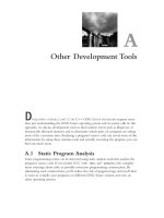
The following sample program is called drawdot and illustrates usage of the l3d library
classes in order to move a green dot around the screen, thereby forming a simple drawing pro-
gram. This program works with visuals of any color depth and in both TrueColor or indexed color
modes. Notice that this program is rather short and declares only one class. This is because the l3d
library has already declared several useful classes to simplify application programs.
8 Chapter 1: Basic Linux 3D Graphics Concepts
Figure 1-7: Output from sample program
drawdot.
TEAM LinG - Live, Informative, Non-cost and Genuine!