Tiêu chuẩn iso 00492 2014
Bạn đang xem bản rút gọn của tài liệu. Xem và tải ngay bản đầy đủ của tài liệu tại đây (1.49 MB, 74 trang )
INTERNATIONAL
STANDARD
ISO
492
Fifth edition
2014-07-15
Corrected version
2014-09-15
Rolling bearings — Radial bearings
— Geometrical product specifications
(GPS) and tolerance values
Roulements — Roulements radiaux — Spécification géométrique des
produits (GPS) et valeurs de tolérance
Reference number
ISO 492:2014(E)
© ISO 2014
ISO 492:2014(E)
COPYRIGHT PROTECTED DOCUMENT
© ISO 2014
All rights reserved. Unless otherwise specified, no part of this publication may be reproduced or utilized otherwise in any form
or by any means, electronic or mechanical, including photocopying, or posting on the internet or an intranet, without prior
written permission. Permission can be requested from either ISO at the address below or ISO’s member body in the country of
the requester.
ISO copyright office
Case postale 56 • CH-1211 Geneva 20
Tel. + 41 22 749 01 11
Fax + 41 22 749 09 47
Web www.iso.org
Published in Switzerland
ii
© ISO 2014 – All rights reserved
ISO 492:2014(E)
Contents
Page
Foreword ........................................................................................................................................................................................................................................ iv
Introduction..................................................................................................................................................................................................................................v
1
2
3
4
5
Scope ................................................................................................................................................................................................................................. 1
Normative references ...................................................................................................................................................................................... 1
Terms and definitions ..................................................................................................................................................................................... 1
Symbols .......................................................................................................................................................................................................................... 1
Limit deviations and tolerance values ........................................................................................................................................17
5.1
General ........................................................................................................................................................................................................ 17
5.2
Radial bearings except tapered roller bearings....................................................................................................... 18
5.3
Radial tapered roller bearings ................................................................................................................................................ 28
5.4
Radial bearings, outer ring flanges ..................................................................................................................................... 41
5.5
Basically tapered bores, tapers 1:12 and 1:30.......................................................................................................... 42
Annex A (informative) Symbols and terms as given in ISO 492:2002 in relation to descriptions
given in this International Standard .............................................................................................................................................44
Annex B (informative) Example of drawing indications of characteristics with specification for
radial bearings.....................................................................................................................................................................................................48
Annex C (informative) Illustration of ISO 1132‑1 and ISO 14405‑1 terms and definitions......................50
Annex D (informative) Description with illustrations for specification modifiers of linear sizes....57
Bibliography ............................................................................................................................................................................................................................. 66
© ISO 2014 – All rights reserved
iii
ISO 492:2014(E)
Foreword
ISO (the International Organization for Standardization) is a worldwide federation of national standards
bodies (ISO member bodies). The work of preparing International Standards is normally carried out
through ISO technical committees. Each member body interested in a subject for which a technical
committee has been established has the right to be represented on that committee. International
organizations, governmental and non-governmental, in liaison with ISO, also take part in the work.
ISO collaborates closely with the International Electrotechnical Commission (IEC) on all matters of
electrotechnical standardization.
The procedures used to develop this document and those intended for its further maintenance are
described in the ISO/IEC Directives, Part 1. In particular the different approval criteria needed for the
different types of ISO documents should be noted. This document was drafted in accordance with the
editorial rules of the ISO/IEC Directives, Part 2 (see www.iso.org/directives).
Attention is drawn to the possibility that some of the elements of this document may be the subject of
patent rights. ISO shall not be held responsible for identifying any or all such patent rights. Details of
any patent rights identified during the development of the document will be in the Introduction and/or
on the ISO list of patent declarations received (see www.iso.org/patents).
Any trade name used in this document is information given for the convenience of users and does not
constitute an endorsement.
For an explanation on the meaning of ISO specific terms and expressions related to conformity
assessment, as well as information about ISO’s adherence to the WTO principles in the Technical Barriers
to Trade (TBT) see the following URL: Foreword - Supplementary information
The committee responsible for this document is ISO/TC 4, Rolling bearings, Subcommittee SC 4,
Tolerances, tolerance definitions and symbols (including GPS).
This fifth edition cancels and replaces the fourth edition (ISO 492:2002), which has been technically
revised.
This corrected version of ISO 492:2014 incorporates the correction of the title.
iv
© ISO 2014 – All rights reserved
ISO 492:2014(E)
Introduction
This International Standard is a machine element geometry standard as defined in the geometrical
product specification (GPS) system as presented in master plan of ISO/TR 14638.[12]
The fundamental rules of ISO/GPS given in ISO 8015[8] apply to this International Standard and the
default decision rules given in ISO 14253-1[10] apply to the specifications made in accordance with this
International Standard, unless otherwise indicated.
The connection between functional requirements, measuring technique and measuring uncertainty is
always intended to be considered. The traditionally used measuring technique is described in ISO 1132-2.
[5] For measurement uncertainty it is intended that ISO 14253-2[11] should be considered.
© ISO 2014 – All rights reserved
v
INTERNATIONAL STANDARD
ISO 492:2014(E)
Rolling bearings — Radial bearings — Geometrical product
specifications (GPS) and tolerance values
1 Scope
This International Standard specifies dimensional and geometrical characteristics, limit deviations from
nominal sizes, and tolerance values to define the interface (except chamfers) of radial rolling bearings.
Nominal boundary dimensions are defined in ISO 15, ISO 355[2] and ISO 8443[9].
This International Standard does not apply to certain radial bearings of particular types (e.g. needle
roller bearings) or for particular fields of application (e.g. airframe bearings and instrument precision
bearings). Tolerances for such bearings are given in the relevant International Standards.
Chamfer dimension limits are given in ISO 582.
2 Normative references
The following documents, in whole or in part, are normatively referenced in this document and are
indispensable for its application. For dated references, only the edition cited applies. For undated
references, the latest edition of the referenced document (including any amendments) applies.
ISO 15, Rolling bearings — Radial bearings — Boundary dimensions, general plan
ISO 582, Rolling bearings — Chamfer dimensions — Maximum values
ISO 1101, Geometrical product specifications (GPS) — Geometrical tolerancing — Tolerances of form,
orientation, location and run-out
ISO 5593, Rolling bearings — Vocabulary
ISO 14405-1, Geometrical product specifications (GPS) — Dimensional tolerancing — Part 1: Linear sizes
ISO/TS 17863, Geometrical product specification (GPS) — Geometrical tolerancing of moveable assemblies
3 Terms and definitions
For the purposes of this document, the terms and definitions given in ISO 1101, ISO 5593, ISO 14405-1,
and ISO/TS 17863 apply.
4 Symbols
To express that the ISO/GPS system, ISO 8015[8], is applied, the dimensional and geometrical
characteristics shall be included in the technical product documentation (for example, on the drawing).
The dimensional and geometrical specifications, associated to these characteristics are described in
Table 1 and Figures 1 to 17.
Descriptions for symbols are in accordance with GPS terminology; relationships with traditional terms
are described in Annex A.
A tolerance value associated to a characteristic is symbolised by t followed by the symbol for the
characteristic, for example t VBs.
In this International Standard, the ISO default specification operator for size is in accordance with
ISO 14405-1, i.e. the two-point size is valid. Some specification modifiers are described in Annex D.
© ISO 2014 – All rights reserved
1
ISO 492:2014(E)
The detailed definitions for terms in ISO 1101 and ISO 14405-1 and traditional terms in ISO 1132-1[4] are
not fully equal. For differences, see Annex C.
Table 1 — Symbols for nominal sizes, characteristics, and specification modifiers
Symbol for
nominal
dimension
(size and
distance)a
Symbol for
characteristica
VBs
GPS symbol and specification modifierbc
GN ALS
e
B
ΔBs
2
GN ALS
e
Descriptiond
See
Figure
Nominal inner ring width
1; 2; 12
Asymmetrical rings: range of minimum
circumscribed sizes of inner ring width,
between two opposite lines, obtained from
any longitudinal section which includes the
inner ring bore axis
2; 7
Symmetrical rings: range of two-point sizes
1; 12
of inner ring width
Symmetrical rings: deviation of a two-point
1; 12
size of inner ring width from its nominal size
Asymmetrical rings, upper limit: deviation
of a minimum circumscribed size of inner
ring width, between two opposite lines, in
any longitudinal section which includes the
2; 7
inner ring bore axis, from its nominal size
Asymmetrical rings, lower limit: deviation
of a two-point size of inner ring width from
its nominal size
© ISO 2014 – All rights reserved
ISO 492:2014(E)
Table 1 — (continued)
Symbol for
nominal
dimension
(size and
distance)a
Symbol for GPS symbol and specificacharaction modifierbc
teristica
VCs
e
GN ALS
C
ΔCs
e
GN ALS
Descriptiond
Nominal outer ring width
1; 7; 12
Asymmetrical rings: range of minimum
circumscribed sizes of outer ring width
between two opposite lines, obtained from
any longitudinal section which includes the
outer ring outside surface axis
2; 12
Symmetrical rings: range of two-point sizes
1; 7
of outer ring width
Symmetrical rings: deviation of a two-point
1; 7
size of outer ring width from its nominal size
Asymmetrical rings, upper limit: deviation
of a minimum circumscribed size of outer
ring width, between two opposite lines,
in any longitudinal section which includes
the outer ring outside surface axis, from its 2; 12
nominal size
Asymmetrical rings, lower limit: deviation
of a two-point size of outer ring width from
its nominal size
C1
ΔC1s
Δdmp
Vdsp
Δds
© ISO 2014 – All rights reserved
12
Deviation of a two-point size of outer ring
flange width from its nominal size
12
Range of mid-range sizes (out of two-point
sizes) of bore diameter obtained from any
cross-section of a cylindrical bore
1; 2; 12
Nominal bore diameter of a cylindrical bore
or at the theoretical small end of a tapered
bore
ACS
ACS
d
Nominal outer ring flange width
Range of two-point sizes of outer ring flange
12
width
VC1s
Vdmp
See
Figure
SCS
ACS
f
1 to 7; 12
to 16
Cylindrical bore: deviation of a midrange size (out of two-point sizes) of bore
1; 2; 12
diameter in any cross-section from its nominal size
Tapered bore: deviation of a mid-range size
(out of two-point sizes) of bore diameter at
7
the theoretical small end from its nominal
size
Range of two-point sizes of bore diameter in
1; 2; 7;
any cross-section of a cylindrical or tapered
12
bore
Deviation of a two-point size of bore diameter of a cylindrical bore from its nominal
size
1; 2; 12
3
ISO 492:2014(E)
Table 1 — (continued)
Symbol for
nominal
dimension
(size and
distancea
d1
Symbol for
characteristia
ΔDmp
VDsp
D1
SCS
Δd1mp
VDmp
D
GPS symbol and specification modifierbc
f
Sd
SD
SD1
4
Deviation of a mid-range size (out of twopoint sizes) of bore diameter at the theoretical large end of a tapered bore from its
nominal size
See Figure
7
7
1 to 16
Range of mid-range sizes (out of two-point
sizes) of outside diameter obtained from any 1; 2; 7; 12
cross-section
ACS
Deviation of a mid-range size (out of twopoint sizes) of outside diameter in any cross- 1; 2; 7; 12
section from its nominal size
ACS
Range of two-point sizes of outside diameter
1; 2; 7; 12
in any cross-section
ACS
Deviation of a two-point size of outside
diameter from its nominal size
Nominal outside diameter of outer ring
flange
ΔD1s
Kia
Nominal diameter at the theoretical large
end of a tapered bore
Nominal outside diameter
ΔDs
Kea
Descriptiond
g
g
g
1; 2; 7; 12
12
Deviation of a two-point size of outside
diameter of outer ring flange from its nomi- 12
nal size
Circular radial run-out of outer ring outside
4; 5; 6; 9;
surface of assembled bearing with respect
10; 11;
to datum, i.e. axis, established from the
14; 15; 16
inner ring bore surface
Circular radial run-out of inner ring bore
surface of assembled bearing with respect
to datum, i.e. axis, established from the
outer ring outside surface
4; 5; 6; 9;
10; 11;
14; 15; 16
Perpendicularity of outer ring outside surface axis with respect to datum established
from the outer ring face
3; 8
Circular axial run-out of inner ring face with
respect to datum, i.e. axis, established from 3; 8; 13
the inner ring bore surface
Perpendicularity of outer ring outside surface axis with respect to datum established
from the outer ring flange back face
13
© ISO 2014 – All rights reserved
ISO 492:2014(E)
Table 1 — (continued)
Symbol for
nominal
dimension
(size and
distance)a
Symbol for GPS symbol and specification
characmodifierbc
teristica
g
Sea
g
Sea1
g
Sia
T1
ΔSL
ΔTs
ΔT1s
GN
GN
T2
ΔT2s
© ISO 2014 – All rights reserved
See Figure
Circular axial run-out of outer ring face
of assembled bearing with respect to
datum, i.e. axis, established from the
inner ring bore surface
5; 6; 10;
11
Circular axial run-out of inner ring face
of assembled bearing with respect to
datum, i.e. axis, established from the
outer ring outside surface
5; 6; 10;
11; 15; 16
Deviation of taper slope of a tapered
inner ring bore from its nominal size i
7
Circular axial run-out of outer ring flange
back face of assembled bearing with
15; 16
respect to datum, i.e. axis, established
from the inner ring bore surface
Taper slope is the difference between
nominal diameters at the theoretical
7
large end and small end of a tapered bore
(d1 − d)
SL h
T
Descriptiond
GN
g
g
g
Nominal assembled bearing width
17
Deviation of minimum circumscribed
size of assembled bearing width from its 17
nominal size
Nominal effective width of inner subunit
17
assembled with a master outer ring
Deviation of minimum circumscribed
size of effective width (inner subunit
assembled with a master outer ring)
from its nominal size
Nominal effective width of outer ring
assembled with a master inner subunit
17
17
Deviation of minimum circumscribed
size of effective width (outer ring assem17
bled with a master inner subunit) from
its nominal size
5
ISO 492:2014(E)
Table 1 — (continued)
Symbol for
nominal
dimension
(size and
distance)a
TF
T F2
Symbol for
characteristica
GPS symbol and specification modifierbc
GN
ΔTFs
GN
ΔTF2s
α
g
g
Descriptiond
Nominal assembled flanged bearing width
17
Deviation of minimum circumscribed size
of assembled flanged bearing width from its 17
nominal size
Nominal effective width of flanged outer
17
ring assembled with a master inner subunit
Deviation of minimum circumscribed size of
effective width (flanged outer ring assem17
bled with a master inner subunit) from its
nominal size
Frustum angle of tapered inner ring bore h
ak
See Figure
Distance from face to define the restricted
area for SD or SD1
7; 8; 9;
10; 11
3; 8; 13
a
Symbols as defined in ISO 15241[15] except for the format used.
c
Specification modifier
shall not be indicated on a drawing, if the two-point size is applied for both specified limits.
f
Specification modifier
can be omitted on the drawing.
h
SL is a distance.
b
d
Symbols as defined in ISO 1101 and ISO 14405-1.
Description based on ISO 1101, ISO 5459[7] and ISO 14405-1.
Specification modifier GN is not appropriate in cases where no opposite material is existing, e.g. tapered roller bearing
outer ring with large back face chamfer and small front face. Solutions need to be developed within the framework of the GPS
system and considered in future revisions of this International Standard.
e
g
Symbols for direction of gravity
5, 6, 9, 10, 11, 14, 15, 16, and 17.
i
G
, fixed parts
and movable parts
, according to ISO/TS 17863; see Figures 4,
Description based on ISO 1119.[3]
k
For rs,min ≤ 0,6: a = rs,max,axial + 0,5; for rs,min > 0,6: a = 1,2 × rs,max,axial; rs,max,axial see ISO 582. For definitions of rs,min
and rs,max,axial see ISO 582.
The indications in Figures 1 to 17 illustrate the correlation of interface dimensions and corresponding
dimensional and geometrical tolerance symbols.
The specifications for single components are illustrated in Figures 1, 2, 3, 7, 8, 12, and 13. The
specifications for assembled components are illustrated in Figures 4, 5, 6, 9, 10, 11, 14, 15, 16, and 17.
NOTE
Figures 1 to 17 are drawn schematically and do not necessarily show all design details.
Two examples of a real drawing indication are given in Annex B.
6
© ISO 2014 – All rights reserved
ISO 492:2014(E)
t VCs SR
t
Cs
Bt
Bs
C
t VDsp SR ACS
t VDmp SD ACS SR
Dmp
/
∅D t
∅D t
Ds
dmp
∅d t
∅d t
ds
/
SD ACS
SD ACS
t Vdsp SR ACS
t Vdmp SD ACS SR
t VBs SR
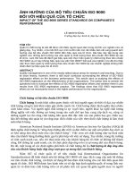
Figure 1 — Size specification for single components for bearing with cylindrical bore and
symmetrical rings
GN ALS
C t Cs LP
M
t VCs GN ALS
t VDsp
tVDmp
Bt
NOTE
Bs
GN ALS
LP
Dmp
∅D t
∅D t
Ds
∅d t ds /
∅d t dmp
/
ACS
ACS
K
ACS
ACS
M
ACS
ACS
t Vdsp
tVdmp
M
K
tVBs GN ALS
K
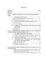
t VBs and t VCs are not relevant for tapered roller bearings.
Figure 2 — Size specification for single components for bearing with cylindrical bore and
asymmetrical rings
© ISO 2014 – All rights reserved
7
ISO 492:2014(E)
A
a
B
B
∅t SD D
∅t SD E
E
D
t Sd K
( ∅ D)
t Sd K
( ∅ d)
K
A
a
Figure 3 — Geometrical tolerances for single components for bearing with cylindrical bore
G
M
t Kea K
1
3
2
K
1
2
3
( ∅d)
( ∅D)
t Kia M
1 = FP 1 - MP 2 , G
2 = FP 2 - MP 1 , G
3 = the rolling elements shall be in contact with both the inner and outer ring raceways
Figure 4 — Geometrical tolerances for assembled bearing with cylindrical bore — Cylindrical
roller bearing, spherical roller bearing, toroidal roller bearing and self‑aligning ball bearing
8
© ISO 2014 – All rights reserved
ISO 492:2014(E)
M
2
t Kea K
t Kea K
1
3
5
5
3
5
t Sea K
t Sea K
1
5
4
5
t Sia M
t Sia M
2
5
t Kia M
t Kia M
2
4
5
5
K
( ∅ d)
( ∅ D)
1
G
G1
G
G2
1 = FP 1 - MP 2 , G2
2 = FP 2 - MP 1 , G2
3 = FP 1 - MP 2 , G1
4 = FP 2 - MP 1 , G1
5 =the rolling elements shall be in contact with both the inner and outer ring raceways
Figure 5 — Geometrical tolerances for assembled bearing with cylindrical bore — Deep-groove
ball bearing, double‑row deep‑groove ball bearing, double‑row angular contact ball bearing
and four-point-contact ball bearing
© ISO 2014 – All rights reserved
9
ISO 492:2014(E)
M
2
1
3
t Sea K
G
G1
( ∅ d)
( ∅ D)
K
t Kea K
1
3
t Sia M
2
3
t Kia M
2
3
1
G
G2
1 = FP 1 - MP 2 , G1
2 = FP 2 - MP 1 , G2
3 = the rolling elements shall be in contact with both the inner and outer ring raceways and, in a
tapered roller bearing, the inner ring back face rib
Figure 6 — Geometrical tolerances for assembled bearing with cylindrical bore — Single-row
angular contact ball bearing and tapered roller bearing
1 = SL is a calculated nominal size from d and d1, i.e. SL = (d1 – d) = 2B tan(α/2); ΔSL is a calculated
NOTE
10
characteristic, i.e. ΔSL = Δd1mp – Δdmp
For indications on asymmetrical outer rings, see Figure 2.
Figure 7 — Size specification for single components for bearing with tapered bore
© ISO 2014 – All rights reserved
ISO 492:2014(E)
a
A
B
D
K
A
a
B
∅t SD D
∅t SD E
E
tSd K
( )
(∅D)
tSd K
Figure 8 — Geometrical tolerances for single components for bearing with tapered bore
G
tKea K 1
M
3
2
K
1
M
M 2
3
( )
(∅D)
t Kia
1 = FP 1 - MP 2 , G
2 = FP 2 - MP 1 , G
3 = the rolling elements shall be in contact with both the inner and outer ring raceways
Figure 9 — Geometrical tolerances for assembled bearing with tapered bore — Cylindrical
roller bearing, spherical roller bearing, toroidal roller bearing and self‑aligning ball bearing
© ISO 2014 – All rights reserved
11
ISO 492:2014(E)
2
M
3
K
5
tSea K
t Kea K
t Kea K
1
3
5
5
t Sea K
1
5
t Sia M
2
5
1
4
5
tSia M
()
(∅D)
t Kia M
t Kia M
G
G1
M 2
M 4
5
5
G
G2
1 = FP 1 - MP 2 , G2
2 = FP 2 - MP 1 , G2
3 = FP 1 - MP 2 , G1
4 = FP 2 - MP 1 , G1
5 = the rolling elements shall be in contact with both the inner and outer ring raceways
Figure 10 — Geometrical tolerances for assembled bearing with tapered bore — Deep-groove
ball bearing, double‑row deep‑groove ball bearing, double‑row angular contact ball bearing
and four-point-contact ball bearing
12
© ISO 2014 – All rights reserved
ISO 492:2014(E)
2
M
1
3
tKea K
1
3
tSia M
2
3
1
tSea K
K
( )
(∅D)
tKia M
G
G1
M
2
3
G
G2
1 = FP 1 - MP 2 , G1
2 = FP 2 - MP 1 , G2
3 = the rolling elements shall be in contact with both the inner and outer ring raceways and, in a
tapered roller bearing, the inner ring back face rib
Figure 11 — Geometrical tolerances for assembled bearing with tapered bore — Single-row
angular contact ball bearing and tapered roller bearing
C
M
GN ALS
t Cs LP
tVDsp
tVDmp
ACS
ACS
M
t VCs GN ALS
C1 t
t VC1s
C1s
M
t Bs
D1s
∅D1 t
∅d t ds /
∅d t dmp
SD ACS
Dmp
/
Ds
∅D t
∅D t
B
NOTE
ACS
ACS
ACS
tVdsp
tVdmp
tVBs
See Figure 2 for indications on asymmetrical inner ring.
Figure 12 — Size specification for single components for bearing with flanged outer ring
© ISO 2014 – All rights reserved
13
ISO 492:2014(E)
D
A
a
A
a
B
∅tSD1 D
tSd K
tSd K
(∅d)
(∅D)
K
B
Figure 13 — Geometrical tolerances for single components for bearing with flanged outer ring
G
1
3
M
t Kea K
2
K
1
t Kia
M
(∅D)
3
(∅d)
2
1 = FP 1 - MP 2 , G
2 = FP 2 - MP 1 , G
3 = the rolling elements shall be in contact with both the inner and outer ring raceways
Figure 14 — Geometrical tolerances for assembled bearing with flanged outer ring —
Cylindrical roller bearing, spherical roller bearing, toroidal roller bearing and self‑aligning ball
bearing
14
© ISO 2014 – All rights reserved
ISO 492:2014(E)
3
1
3
M
5
4
5
5
5
t Sea1 K
t Kea K
t Kea K
2
tSia M
K
(∅d)
(∅D)
1
G
tSia M 2
5
tKia M 2
tKia M 4
5
5
G
1 = FP 1 - MP 2 , G2
2 = FP 2 - MP 1 , G2
3 = FP 1 - MP 2 , G1
4 = FP 2 - MP 1 , G1
5 = the rolling elements shall be in contact with both the inner and outer ring raceways
Figure 15 — Geometrical tolerances for assembled bearing with flanged outer ring — Deep‑
groove ball bearing, double‑row deep‑groove ball bearing, double‑row angular contact ball
bearing and four-point-contact ball bearing
© ISO 2014 – All rights reserved
15
ISO 492:2014(E)
M
1
1
tSea1 K
t Kea K
3
3
2
1
(∅d)
(∅D)
K
G
G1
tSia M
2
3
tKia M
2
3
G
G2
1 = FP 1 - MP 2 , G1
2 = FP 2 - MP 1 , G2
3 = the rolling elements shall be in contact with both the inner and outer ring raceways and, in a
tapered roller bearing, the inner ring back face rib
Figure 16 — Geometrical tolerances for assembled bearing with flanged outer ring — Single‑
row angular contact ball bearing and tapered roller bearing
16
© ISO 2014 – All rights reserved
ISO 492:2014(E)
T
t
Ts
T1 t
1
GN
T1s
GN
2
1
T2
t
T2s
1
GN
2
2
1
2
G
G1
G
G1
G
G2
TF
t
TFs
GN 1
2
TF2
G
G2
G
G1
t
GN 1
TF2s
G
G2
2
2
G
G1
1 =
2 =
G
G2
G
G1
G
G2
G1 or G2
the rolling elements shall be in contact with both the inner and outer ring raceways and the
inner ring back face rib
Key
1 master outer ring
2 master inner subunit
Figure 17 — Additional symbols for assembled tapered roller bearings
5 Limit deviations and tolerance values
5.1 General
The bore diameter limit deviations and tolerance values for cylindrical bores are given in 5.2 and 5.3
and for flanges in 5.4. The limit deviations and tolerance values for tapered bore are given in 5.5.
© ISO 2014 – All rights reserved
17
ISO 492:2014(E)
The diameter series referred to in Tables 2 to 11 are those defined in ISO 15. In the Tables 2 to 27 the
symbols U and L are used as follows:
— U = upper limit deviation;
— L = lower limit deviation.
5.2 Radial bearings except tapered roller bearings
5.2.1
Tolerance class — Normal
See Tables 2 and 3.
Table 2 — Radial bearings except tapered roller bearings — Inner ring — Tolerance class —
Normal
d
>
—
mm
≤
U
10
0
0,6
0,6
2,5
18
30
2,5
10
30
50
80
120
18
0
L
180
0
0
31
31
−20
0
−40
630
800
0
−75
800
1 000
0
1 600
2 000
500
1 000
1 250
630
1 250
1 600
0
0
0
0
10
−25
−15
400
0
13
8
12
315
500
0
6
6
6
8
15
−30
400
10
8
10
8
−12
0
0
6
10
10
250
315
6
2, 3, 4
−8
−8
180
250
All
0, 1
10
−10
0
tKia
9
−8
0
0
t Vdmp
Diameter series
−8
0
120
t Vdsp
0
50
80
tΔdmp
Limit deviations and tolerance values in micrometres
19
25
38
19
25
−200
0
−120
−250
20
11
11
20
0
−150
−380
25
9
15
19
9
15
19
0
−200
−250
−380
20
25
−250
−500
30
−350
−500
35
30
30
60
0
−400
−630
40
—
80
0
−750
—
70
—
100
26
63
63
—
—
—
—
—
30
0
−120
50
26
34
—
25
0
15
−300
34
—
15
−120
−250
0
−100
−160
13
0
−120
12
40
−50
−125
20
8
56
—
−250
8
10
0
—
23
44
56
12
10
10
−40
—
23
44
−45
−40
L
t VBs
6
6
0
Normal Modifieda
38
−35
50
6
U
tΔBs
—
—
—
—
38
—
—
—
—
38
—
—
50
0
65
0
90
0
−1 000
—
0
−2 000
—
70
120
140
0
0
0
−450
−500
−500
−1 250
−1 600
—
—
—
—
30
50
60
80
100
120
140
a
Applies to inner rings and outer rings of single bearings made for paired and stack assemblies. Also
applies to inner rings with tapered bore with d ≥ 50 mm.
18
© ISO 2014 – All rights reserved
ISO 492:2014(E)
Table 3 — Radial bearings except tapered roller bearings — Outer ring — Tolerance class —
Normal
D
>
mm
≤
U
18
0
2,5
18
30
−8
50
0
−11
80
120
0
180
250
30
50
120
150
250
80
150
180
315
1 600
2 000
1 250
2 000
NOTE
1 600
2 500
−18
0
−30
0
−40
−75
0
0
1 000
6
10
−25
1 250
1 000
8
10
0
0
800
10
10
16
800
630
2, 3, 4
−13
0
0
0
0
0
0
0
15
2, 3, 4
0
−15
8
0, 1
12
630
500
−8
tKea
9
−9
400
500
b
0
315
400
a
−8
0
6
6
0
L
Capped
bearings t VDmp a
Diameter series
Open bearings
tΔDmp
—
2,5
t VDsp a
14
19
23
31
38
8
9
11
13
−50
63
63
94
50
125
−200
—
—
−160
−250
—
—
14
—
—
—
16
—
23
—
30
30
—
10
40
26
60
—
34
—
75
55
—
—
—
—
—
—
38
45
50
70
80
120
—
160
—
—
L
t VC1s b
Identical to tΔBs and
t VBs of an inner ring
of the same bearing
as the outer ring
100
55
—
U
t VCs
25
14
19
tΔC1s b
15
35
38
—
7
tΔCs
15
11
—
—
6
15
26
26
—
6
20
38
30
6
8
19
75
125
—
20
34
−100
−125
10
8
56
94
10
12
23
31
10
7
38
23
44
56
6
11
44
50
6
19
−35
−45
Limit deviations and tolerance values in micrometres
140
190
220
250
The limit deviations for the outside diameter, D1, of an outer ring flange are given in Table 25.
Applies before mounting and after removal of internal or external snap ring.
Applies to groove ball bearings only.
© ISO 2014 – All rights reserved
19