Tiêu chuẩn iso 00463 2006
Bạn đang xem bản rút gọn của tài liệu. Xem và tải ngay bản đầy đủ của tài liệu tại đây (343.5 KB, 22 trang )
INTERNATIONAL
STANDARD
ISO
463
First edition
2006-03-01
Geometrical Product Specifications
(GPS) — Dimensional measuring
equipment — Design and metrological
characteristics of mechanical dial gauges
Spécification géométrique des produits (GPS) — Instruments de
mesurage dimensionnel: Comparateurs mécaniques à cadran —
Caractéristiques de conception et caractéristiques métrologiques
Reference number
ISO 463:2006(E)
--`,,```,,,,````-`-`,,`,,`,`,,`---
Copyright International Organization for Standardization
Provided by IHS under license with ISO
No reproduction or networking permitted without license from IHS
© ISO 2006
Not for Resale
ISO 463:2006(E)
PDF disclaimer
This PDF file may contain embedded typefaces. In accordance with Adobe's licensing policy, this file may be printed or viewed but
shall not be edited unless the typefaces which are embedded are licensed to and installed on the computer performing the editing. In
downloading this file, parties accept therein the responsibility of not infringing Adobe's licensing policy. The ISO Central Secretariat
accepts no liability in this area.
Adobe is a trademark of Adobe Systems Incorporated.
Details of the software products used to create this PDF file can be found in the General Info relative to the file; the PDF-creation
parameters were optimized for printing. Every care has been taken to ensure that the file is suitable for use by ISO member bodies. In
the unlikely event that a problem relating to it is found, please inform the Central Secretariat at the address given below.
© ISO 2006
All rights reserved. Unless otherwise specified, no part of this publication may be reproduced or utilized in any form or by any means,
electronic or mechanical, including photocopying and microfilm, without permission in writing from either ISO at the address below or
ISO's member body in the country of the requester.
ISO copyright office
Case postale 56 • CH-1211 Geneva 20
Tel. + 41 22 749 01 11
Fax + 41 22 749 09 47
Web www.iso.org
Published in Switzerland
--`,,```,,,,````-`-`,,`,,`,`,,`---
ii
Copyright International Organization for Standardization
Provided by IHS under license with ISO
No reproduction or networking permitted without license from IHS
© ISO 2006 – All rights reserved
Not for Resale
ISO 463:2006(E)
Contents
Page
Foreword............................................................................................................................................................ iv
1
Scope ..................................................................................................................................................... 1
2
Normative references ........................................................................................................................... 1
3
Terms and definitions........................................................................................................................... 1
4
4.1
4.2
4.3
4.4
4.5
4.6
4.7
4.8
Design characteristics.......................................................................................................................... 2
General................................................................................................................................................... 2
Dimensions............................................................................................................................................ 2
Dial and pointer..................................................................................................................................... 5
Revolution counting device................................................................................................................. 6
Contact element .................................................................................................................................... 6
Zero adjustment .................................................................................................................................... 6
Movable limit indicators ....................................................................................................................... 7
Design characteristics (manufacturer’s specification)..................................................................... 7
5
5.1
5.2
5.3
Metrological characteristics ................................................................................................................ 7
MPE and MPL for a number of metrological characteristics ........................................................... 7
Contact element .................................................................................................................................... 8
Measuring forces .................................................................................................................................. 8
6
6.1
6.2
Proving conformance with specification ........................................................................................... 8
General................................................................................................................................................... 8
Measurement standards for calibration of metrological characteristics........................................ 8
7
Marking .................................................................................................................................................. 8
Annex A (informative) Example diagram of errors of indication ................................................................... 9
Annex B (informative) Example data sheet for mechanical dial gauges .................................................... 10
Annex C (informative) Calibration of metrological characteristics ............................................................. 11
Annex D (informative) Relation to the GPS matrix model ............................................................................ 12
Bibliography ..................................................................................................................................................... 14
iii
© ISO 2006 – All rights reserved
Copyright International Organization for Standardization
Provided by IHS under license with ISO
No reproduction or networking permitted without license from IHS
Not for Resale
--`,,```,,,,````-`-`,,`,,`,`,,`---
Introduction ........................................................................................................................................................ v
ISO 463:2006(E)
Foreword
ISO (the International Organization for Standardization) is a worldwide federation of national standards bodies
(ISO member bodies). The work of preparing International Standards is normally carried out through ISO
technical committees. Each member body interested in a subject for which a technical committee has been
established has the right to be represented on that committee. International organizations, governmental and
non-governmental, in liaison with ISO, also take part in the work. ISO collaborates closely with the
International Electrotechnical Commission (IEC) on all matters of electrotechnical standardization.
International Standards are drafted in accordance with the rules given in the ISO/IEC Directives, Part 2.
The main task of technical committees is to prepare International Standards. Draft International Standards
adopted by the technical committees are circulated to the member bodies for voting. Publication as an
International Standard requires approval by at least 75 % of the member bodies casting a vote.
Attention is drawn to the possibility that some of the elements of this document may be the subject of patent
rights. ISO shall not be held responsible for identifying any or all such patent rights.
ISO 463 was prepared by Technical Committee ISO/TC 213, Dimensional and geometrical product
specifications and verification.
This first edition of ISO 463 cancels and replaces ISO/R 463:1965, which has been technically revised.
--`,,```,,,,````-`-`,,`,,`,`,,`---
iv
Copyright International Organization for Standardization
Provided by IHS under license with ISO
No reproduction or networking permitted without license from IHS
© ISO 2006 – All rights reserved
Not for Resale
ISO 463:2006(E)
Introduction
This International Standard is a geometrical product specification (GPS) standard and is to be regarded as a
general GPS standard (see ISO/TR 14638). It influences the chain link 5 of the chains of standards on size,
distance, form of a line independent of datum, form of a line dependent of datum, form of a surface
independent of datum, form of a surface independent of datum, orientation, location, circular run-out and total
run-out in the general GPS matrix.
--`,,```,,,,````-`-`,,`,,`,`,,`---
For more detailed information of the relation of the standard to other standards and the GPS matrix model see
Annex D.
© ISO 2006 – All rights reserved
Copyright International Organization for Standardization
Provided by IHS under license with ISO
No reproduction or networking permitted without license from IHS
Not for Resale
v
--`,,```,,,,````-`-`,,`,,`,`,,`---
Copyright International Organization for Standardization
Provided by IHS under license with ISO
No reproduction or networking permitted without license from IHS
Not for Resale
INTERNATIONAL STANDARD
ISO 463:2006(E)
Geometrical Product Specifications (GPS) — Dimensional
measuring equipment — Design and metrological
characteristics of mechanical dial gauges
1
Scope
This International Standard specifies the most important design and metrological characteristics of mechanical
dial gauges.
2
Normative references
The following referenced documents are indispensable for the application of this document. For dated
references, only the edition cited applies. For undated references, the latest edition of the referenced
document (including any amendments) applies.
ISO 14253-1, Geometrical Product Specifications (GPS) — Inspection by measurement of workpieces and
measuring equipment — Part 1: Decision rules for proving conformance or non-conformance with
specifications
ISO/TS 14253-2, Geometrical Product Specifications (GPS) — Inspection by measurement of workpieces and
measuring equipment — Part 2: Guide to the estimation of uncertainty in GPS measurement, in calibration of
measuring equipment and in product verification
ISO 14978:— 1), Geometrical Product Specification (GPS) — General concepts and requirement for GPS
measuring equipment
Guide to the expression of uncertainty in measurement (GUM). BIPM, IEC, IFCC, ISO, IUPAC, IUPAP, OIML,
1st edition, 1993, corrected and reprinted in 1995.
International Vocabulary of Basic and General Terms in Metrology (VIM). BIPM, IEC, IFCC, ISO, IUPAC,
IUPAP, OIML, 2nd edition, 1993.
3
Terms and definitions
For the purposes of this document, the terms and definitions given in ISO 14253-1, ISO/TS 14253-2,
ISO 14978, VIM and the following apply.
3.1
mechanical dial gauge
measuring instrument in which the axial displacements of a plunger are transmitted and magnified by suitable
mechanical means to a pointer which rotates in front of an analog circular scale
NOTE
It may also be provided with a revolution-counting device, e.g. in which a pointer rotates in front of a scale
which indicates the number of revolutions of the pointer or the axial displacement of the plunger.
1)
To be published.
--`,,```,,,,````-`-`,,`,,`,`,,`---
1
© ISO 2006 – All rights reserved
Copyright International Organization for Standardization
Provided by IHS under license with ISO
No reproduction or networking permitted without license from IHS
Not for Resale
ISO 463:2006(E)
4
4.1
Design characteristics
General
The general design and workmanship shall be such that the performance of the dial gauge complies with the
requirements of this International Standard unless otherwise specified by the manufacturer.
The design and rigidity of the dial gauge shall be such that the freedom of movement of the plunger is not
impaired by clamping the stem of the instrument, providing that such clamping is applied to the minimum
extent necessary to achieve a stable mounting. Where alternative methods of mounting are used, e.g.
attaching the lug on the back plate, the design and rigidity of that mounting shall be such that the performance
is not impaired.
4.2
Dimensions
The dial gauge shall conform to the dimensions specified in Figures 1, 2 and Table 1 to ensure
interchangeability.
Table 1 — Main dimensions
Values in millimetres
Bezel diameter
D1
Size classification
30
40
60
80
100
28 to 36
37 to 50
51 to 70
71 to 89
90 to 115
Stem diameter D2
8 h6
8 h6
8 h6
8 h6
8 h6
Contact element outside diameter D3
u 7,5
u 7,5
u 7,5
u 7,5
u 7,5
Thread size D4
M2,5-6H
M2,5-6H
M2,5-6H
M2,5-6H
M2,5-6H
Thread size D5
M2,5-6g
M2,5-6g
M2,5-6g
M2,5-6g
M2,5-6g
Clamp diameter D6 b
28 h6
28 h6
28 h6
28 h6
28 h6
Stem length L1
W 8,5
W 10
W 12
W 15,5
W 9,5
Length L2 c
u 12
u 28
u 34
d
d
Thread length L3
u5
u5
u5
u5
u5
Thread length L4
W6
W6
W6
W6
W6
Contact distance, centreline to back, L5
u 10
u 10
u 10
u 10
u 10
Range of bezel diameter D1 a
a
Actual bezel diameter equals width.
b
The clamp diameter D6 is optional.
c
Plunger pressed in.
d
Depending on the measuring range.
2
Copyright International Organization for Standardization
Provided by IHS under license with ISO
No reproduction or networking permitted without license from IHS
--`,,```,,,,````-`-`,,`,,`,`,,`---
© ISO 2006 – All rights reserved
Not for Resale
ISO 463:2006(E)
--`,,```,,,,````-`-`,,`,,`,`,,`---
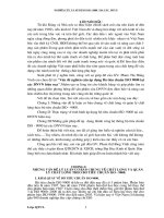
Key
1
scale
4
bezel
7
stem
10
dial cover
2
3
limit indicator
dial
5
6
pointer
revolution counting device
8
9
plunger
contact element
a
Maximum required space.
Measuring face.
b
Figure 1 — Nomenclature and general design of dial gauge
3
© ISO 2006 – All rights reserved
Copyright International Organization for Standardization
Provided by IHS under license with ISO
No reproduction or networking permitted without license from IHS
Not for Resale
ISO 463:2006(E)
--`,,```,,,,````-`-`,,`,,`,`,,`---
a
See Figure 1.
Figure 2 — Nomenclature and general design of dial gauge with plunger at rear
4
Copyright International Organization for Standardization
Provided by IHS under license with ISO
No reproduction or networking permitted without license from IHS
© ISO 2006 – All rights reserved
Not for Resale
ISO 463:2006(E)
4.3
Dial and pointer
--`,,```,,,,````-`-`,,`,,`,`,,`---
The circular scale shall be graduated in scale intervals. The scale interval and its unit shall be clearly identified.
Two examples of scale layouts are shown in Figure 3 (scale interval: 0,01 mm, 0,001 mm).
a) Scale for multiple revolutions
b) Scale for partial revolution
Figure 3 — Examples of scale layouts
The pointer shall move in a clockwise direction when the plunger is pressed into the gauge.
For dial gauges with more than one pointer revolution [dial layout according to Figure 3 a)]:
⎯
When the long pointer is in the position of rest and the zero mark on the dial is at 12 o’clock, the pointer
shall lie at least 1/10th of the scale range in an anticlockwise position (pre-span). Travel beyond the
measuring range (post-span) shall be not less than 1/10th of the scale range [see Figure 4 a)].
For dial gauges with less than one pointer revolution [dial layout according to Figure 3 b)]:
⎯
When the plunger is in the position of rest, the pointer shall lie at least 3 scale intervals in an
anticlockwise position (pre-span). The post-span (travel beyond the measuring range) shall be such that
the pointer does not reach the position which it has in the position of rest. But the post-span shall be at
least 3 scale intervals [see Figure 4 b)].
5
© ISO 2006 – All rights reserved
Copyright International Organization for Standardization
Provided by IHS under license with ISO
No reproduction or networking permitted without license from IHS
Not for Resale
--`,,```,,,,````-`-`,,`,,`,`,,`---
ISO 463:2006(E)
a) Dial gauge with multiple revolutions
b) Dial gauge with partial revolution
Key
A
pre-span
B
post-span
Figure 4 — Examples of pre-span and post-span
4.4
Revolution counting device
When a revolution counting device is provided, its pointer shall indicate the appropriate division on its scale
when the pointer is at 12 o’clock on each of its revolutions.
4.5
Contact element
The contact element shall be replaceable. It shall have a wear-resistant measuring surface and shall be of
suitable form and surface finish (see Figure 1).
4.6
Zero adjustment
Each dial gauge shall be provided with a reliable means of resetting the gauge to zero that cannot be
unintentionally displaced (other than by the application of excessive force), e.g. through provision of setting a
locking device such as a clamp or by frictional resistance.
6
Copyright International Organization for Standardization
Provided by IHS under license with ISO
No reproduction or networking permitted without license from IHS
© ISO 2006 – All rights reserved
Not for Resale
ISO 463:2006(E)
4.7
Movable limit indicators
Limit indicators, where provided shall not unduly impair visibility of the scale markings (see Figure 1).
4.8
Design characteristics (manufacturer’s specification)
As a minimum requirement the manufacturer shall specify at least the information set out in Table 2 (see
Annex B).
Table 2 — Design characteristics
Characteristic
Maximum
required space
Width
W
Thickness
T
Height
H
mm
Measuring range
Scale interval
Presence of
a
plunger lifting device
Yes/No
attachment mounting and type a
Yes/No
fluid and dust protection
(Code IP)/No
plunger shock protection
Yes/No
To be defined by the manufacturer.
5
Metrological characteristics
5.1
MPE and MPL for a number of metrological characteristics
Maximum permissible error MPE is the extreme value of an error of a metrological characteristic permitted by
the specification.
Maximum permissible limit MPL is the extreme value of a metrological characteristic permitted by the
specification.
The manufacturer shall specify MPE and MPL information for the dial gauge metrological characteristics given
in Table 3. Unless otherwise specified by the manufacturer, the static response of the dial gauge shall comply
with these hysteresis and repeatability of error of indication MPE/MPL values at any position within the
measuring range and at any orientation of the dial gauge (see Table 3).
--`,,```,,,,````-`-`,,`,,`,`,,`---
7
© ISO 2006 – All rights reserved
Copyright International Organization for Standardization
Provided by IHS under license with ISO
No reproduction or networking permitted without license from IHS
Not for Resale
ISO 463:2006(E)
Table 3 — Metrological characteristics
MPE
or
MPL
Characteristic
Hysteresis of error of indication a
Repeatability of error of indication
any 1/10 revolution
Errors of indication over a range of
µm
any 1/2 revolution
one revolution
the measuring range
maximum
Measuring force
N
minimum
hysteresis
NOTE
a
5.2
For the indication of the numerical values of the MPE and MPL, the data sheet given in Annex B can be used.
The discrimination is nearly half the hysteresis.
Contact element
The contact element and its metrological characteristics shall be appropriate for the intended measuring task.
5.3
Measuring forces
Measuring forces shall be given as the maximum measuring force, the minimum measuring force and the
hysteresis of the measuring force.
The measuring force characteristics are based on a two-sided specification given in ISO 14978:—, 7.5.6.
6
6.1
Proving conformance with specification
General
For proving conformance/non-conformance with specification, ISO 14253-1 applies. Uncertainty evaluation
shall be performed according to ISO/TS 14253-2 and GUM.
6.2
Measurement standards for calibration of metrological characteristics
Measurement standards shall be used in accordance with the applicable International Standards.
7
Marking
The dial gauge shall be marked with serialized alpha-numeric identification.
Any marking shall be easily readable and permanent and shall be placed on the surface of the dial gauge
such that it will not impair the metrological quality of the equipment.
--`,,```,,,,````-`-`,,`,,`,`,,`---
8
Copyright International Organization for Standardization
Provided by IHS under license with ISO
No reproduction or networking permitted without license from IHS
© ISO 2006 – All rights reserved
Not for Resale
ISO 463:2006(E)
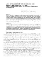
Annex A
(informative)
Example diagram of errors of indication
Figure A.1 shows an example of a diagram of errors of indication. This is a simplified data set (for data points)
in order to illustrate the characteristics of the dial gauge. See also ISO 14978:—, Clause 7.
--`,,```,,,,````-`-`,,`,,`,`,,`---
Key
X
Y
nominal value
error of indication
a
Error curve (plunger outward movement).
b
Error curve (plunger inward movement).
c
Hysteresis at one particular nominal value.
d
Error of indication (maximum) in both directions of plunger (floating zero).
e
Error of indication in one direction of plunger.
Figure A.1 — Diagram of errors of indication
9
© ISO 2006 – All rights reserved
Copyright International Organization for Standardization
Provided by IHS under license with ISO
No reproduction or networking permitted without license from IHS
Not for Resale
ISO 463:2006(E)
Annex B
(informative)
Example data sheet for mechanical dial gauges
This data sheet is intended for communication between technical experts and the purchasing department of
the same company.
Name of equipment:
............................................................................................................
Detailed requirements:
............................................................................................................
(scale layout, contact element, protection
against fluid and dust, shock protection,
lifting device, attachment mounting and
type, etc.)
............................................................................................................
Accessories:
............................................................................................................
Possible suppliers/manufacturers:
............................................................................................................
Price range (optional):
............................................................................................................
Additional requirements:
............................................................................................................
(e.g. inspection report, calibration certificate)
............................................................................................................
............................................................................................................
............................................................................................................
The design and metrological characteristics refer to ISO 463.
--`,,```,,,,````-`-`,,`,,`,`,,`---
Design characteristics
Overall dimensions:
Thickness, T: .................. mm
Measuring range:
Scale interval:
Width, W: .................. mm
Height, H: ................. mm
...................... mm
...................... mm
Metrological characteristics
Hysteresis of indication (MPE) ............ µm
Repeatability of indication (MPE) ............ µm
Errors (MPE) of indication over a range of:
any 1/10 revolution
......... µm
any 1/2 revolution
......... µm
1 revolution
......... µm
the measuring range
......... µm
Measuring forces (MPL)
maximum
.............. N
minimum
.............. N
hysteresis
.............. N
MPE and MPL in the following orientations:
any
vertical
horizontal
Company ...............................................................
Department..........................................
Person responsible ................................. Date ................................
10
Copyright International Organization for Standardization
Provided by IHS under license with ISO
No reproduction or networking permitted without license from IHS
© ISO 2006 – All rights reserved
Not for Resale
ISO 463:2006(E)
Annex C
(informative)
Calibration of metrological characteristics
The methods should evaluate the performance of the instrument within its measuring range using both
directions of displacement of the plunger.
It is essential that the dial gauge be held rigidly in a fixture which is undisturbed by the operating force of the
instrument itself.
The global calibration of a sufficient number of scale points over the measuring range will necessitate a large
number of readings to be taken. When it is considered that the intended use of the dial gauge does not
warrant global calibration, partial calibration or task-related calibration should be considered.
For the determination of the indication errors according to Table 3, a suitable number of intervals are
necessary which are dependent on the scale interval and the measuring range or the used measuring range.
By these values calibration curves with fixed or floating zeros can be recorded. The MPE-function for the
characteristics is given as only one two-sided specification with the constant symmetrical limits USL and LSL
as the MPE for the measuring range (see ISO 14978:—, Figure 9).
It is possible to perform a modified global calibration with a reduced number of scale points by using a suitable
sampling technique but this will result in an increase in the uncertainty of measurement.
Annex A shows an example of a diagram (with a very small number of scale points) of errors of indication
(calibration curve) and hysteresis band of a dial gauge where zero was fixed at the lower limit of the
measuring span.
--`,,```,,,,````-`-`,,`,,`,`,,`---
By means of these measuring values the errors for various measured lengths over the measuring range could
be calculated (see ISO 14978:—, Figure 7), i.e. the dial gauge is also used with floating zero indicating
measuring equipment (see ISO 14978:—, 7.2.2).
11
© ISO 2006 – All rights reserved
Copyright International Organization for Standardization
Provided by IHS under license with ISO
No reproduction or networking permitted without license from IHS
Not for Resale
ISO 463:2006(E)
Annex D
(informative)
Relation to the GPS matrix model
For full details about the GPS matrix model see ISO/TR 14638.
D.1 Information about this International Standard and its use
This International Standard provides the most important design and metrological characteristics of mechanical
dial gauges.
ISO 463 specifies the most important metrological and design characteristics of mechanical dial gauges. Only
those design characteristics which are critical to interchangeability have been assigned requirement values.
The metrological characteristics are not subject to requirement values as it is the philosophy that the values of
these characteristics are matters of the manufacturer and/or user. However, ISO 463 provides definition of the
metrological characteristics and states those metrological characteristics for which the manufacturer shall
state a MPE or MPL value.
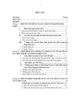
D.2 Position in the GPS matrix model
This International Standard is a general GPS standard, which influences the chain link 5 of the chains of
standards on size, distance, form of a line independent of datum, form of a line dependent of datum, form of a
surface independent of datum, form of a surface dependent of datum, orientation, location, circular run-out
and total run-out in the general GPS matrix, as graphically illustrated in Figure D.1
12
Copyright International Organization for Standardization
Provided by IHS under license with ISO
No reproduction or networking permitted without license from IHS
--`,,```,,,,````-`-`,,`,,`,`,,`---
© ISO 2006 – All rights reserved
Not for Resale
ISO 463:2006(E)
Global GPS standards
General GPS standards
Chain link number
1
2
3
4
5
6
Size
Distance
Radius
Angle
Form of a line independent of datum
Form of a line dependent of datum
Form of a surface independent of datum
Form of a surface dependent of datum
Fundamental
GPS
standards
Orientation
Location
Circular run-out
Total run-out
Datums
Roughness profile
Waviness profile
Primary profile
Surface imperfections
Edges
Figure D.1 — GPS matrix
D.3 Related standards
The related standards are those of the chains of standards indicated in Figure D.1.
--`,,```,,,,````-`-`,,`,,`,`,,`---
13
© ISO 2006 – All rights reserved
Copyright International Organization for Standardization
Provided by IHS under license with ISO
No reproduction or networking permitted without license from IHS
Not for Resale
ISO 463:2006(E)
Bibliography
ISO/TR 14638:1995, Geometrical product specification (GPS) — Masterplan
[2]
IEC 60529:2001, Degrees of protection provided by enclosures (IP Code)
--`,,```,,,,````-`-`,,`,,`,`,,`---
[1]
14
Copyright International Organization for Standardization
Provided by IHS under license with ISO
No reproduction or networking permitted without license from IHS
© ISO 2006 – All rights reserved
Not for Resale