Tiêu chuẩn iso 03302 2 2008
Bạn đang xem bản rút gọn của tài liệu. Xem và tải ngay bản đầy đủ của tài liệu tại đây (166.64 KB, 14 trang )
INTERNATIONAL
STANDARD
ISO
3302-2
Second edition
2008-10-01
Rubber — Tolerances for products —
Part 2:
Geometrical tolerances
Caoutchouc — Tolérances pour produits —
Partie 2: Tolérances géométriques
Reference number
ISO 3302-2:2008(E)
© ISO 2008
ISO 3302-2:2008(E)
PDF disclaimer
This PDF file may contain embedded typefaces. In accordance with Adobe's licensing policy, this file may be printed or viewed but
shall not be edited unless the typefaces which are embedded are licensed to and installed on the computer performing the editing. In
downloading this file, parties accept therein the responsibility of not infringing Adobe's licensing policy. The ISO Central Secretariat
accepts no liability in this area.
Adobe is a trademark of Adobe Systems Incorporated.
Details of the software products used to create this PDF file can be found in the General Info relative to the file; the PDF-creation
parameters were optimized for printing. Every care has been taken to ensure that the file is suitable for use by ISO member bodies. In
the unlikely event that a problem relating to it is found, please inform the Central Secretariat at the address given below.
COPYRIGHT PROTECTED DOCUMENT
© ISO 2008
All rights reserved. Unless otherwise specified, no part of this publication may be reproduced or utilized in any form or by any means,
electronic or mechanical, including photocopying and microfilm, without permission in writing from either ISO at the address below or
ISO's member body in the country of the requester.
ISO copyright office
Case postale 56 • CH-1211 Geneva 20
Tel. + 41 22 749 01 11
Fax + 41 22 749 09 47
Web www.iso.org
Published in Switzerland
ii
© ISO 2008 – All rights reserved
ISO 3302-2:2008(E)
Contents
Page
Foreword............................................................................................................................................................ iv
1
Scope ..................................................................................................................................................... 1
2
Normative references ........................................................................................................................... 1
3
Classes of tolerances ........................................................................................................................... 1
4
4.1
4.2
Measurement of dimensions ............................................................................................................... 2
General................................................................................................................................................... 2
Test instruments ................................................................................................................................... 2
5
Flatness tolerance ................................................................................................................................ 2
6
6.1
6.2
Parallelism tolerance ............................................................................................................................ 3
Sandwich structure (rubber between two metal plates) ................................................................... 3
Extruded-product cut section (e.g. lathe-cut rings) ............................................................................ 4
7
Perpendicularity tolerance................................................................................................................... 5
8
8.1
8.2
8.3
Coaxiality tolerance .............................................................................................................................. 5
Moulded products................................................................................................................................. 5
Mandrel-supported extruded products............................................................................................... 7
Rotating parts........................................................................................................................................ 7
9
Positional tolerances............................................................................................................................ 8
© ISO 2008 – All rights reserved
iii
ISO 3302-2:2008(E)
Foreword
ISO (the International Organization for Standardization) is a worldwide federation of national standards bodies
(ISO member bodies). The work of preparing International Standards is normally carried out through ISO
technical committees. Each member body interested in a subject for which a technical committee has been
established has the right to be represented on that committee. International organizations, governmental and
non-governmental, in liaison with ISO, also take part in the work. ISO collaborates closely with the
International Electrotechnical Commission (IEC) on all matters of electrotechnical standardization.
International Standards are drafted in accordance with the rules given in the ISO/IEC Directives, Part 2.
The main task of technical committees is to prepare International Standards. Draft International Standards
adopted by the technical committees are circulated to the member bodies for voting. Publication as an
International Standard requires approval by at least 75 % of the member bodies casting a vote.
Attention is drawn to the possibility that some of the elements of this document may be the subject of patent
rights. ISO shall not be held responsible for identifying any or all such patent rights.
ISO 3302-2 was prepared by Technical Committee ISO/TC 45, Rubber and rubber products, Subcommittee
SC 4, Products (other than hoses).
This second edition cancels and replaces the first edition (ISO 3302-2:1998), of which it constitutes a minor
revision, the main purpose of which was to correct Figure 5, revise Subclause 4.2.1 and update the normative
references.
ISO 3302 consists of the following parts, under the general title Rubber — Tolerances for products:
⎯
Part 1: Dimensional tolerances
⎯
Part 2: Geometrical tolerances
iv
© ISO 2008 – All rights reserved
INTERNATIONAL STANDARD
ISO 3302-2:2008(E)
Rubber — Tolerances for products —
Part 2:
Geometrical tolerances
1
Scope
This part of ISO 3302 specifies the following geometrical tolerances for moulded and extruded solid rubber
products, including those with metal inserts:
⎯
flatness tolerance;
⎯
parallelism tolerance;
⎯
perpendicularity tolerance;
⎯
coaxiality tolerance;
⎯
positional tolerance.
The tolerances are primarily intended for use with vulcanized rubber but may also be suitable for products
made of thermoplastic rubbers.
2
Normative references
The following referenced documents are indispensable for the application of this document. For dated
references, only the edition cited applies. For undated references, the latest edition of the referenced
document (including any amendments) applies.
ISO 1101:2004, Geometrical Product Specifications (GPS) — Geometrical tolerancing — Tolerances of form,
orientation, location and run-out
ISO 2230, Rubber products — Guidelines for storage
ISO 23529, Rubber — General procedures for preparing and conditioning test pieces for physical test
methods
3
Classes of tolerances
Three classes of tolerance are specified, as follows:
P
Precision
M
Medium
N
Non-critical
© ISO 2008 – All rights reserved
1
ISO 3302-2:2008(E)
The necessary tolerance class depends on the requirements of the application. Tolerance classes M and P
require more manufacturing effort and to some extent finishing, e.g. by grinding.
It is impossible to illustrate every design of moulded product and the cross-section of every extruded product.
Therefore the tolerances shown in Figures 1 to 6 should be regarded simply as examples.
Details and descriptions of the so-called “tolerance frame” and “tolerance zone” are given in ISO 1101:2004,
Clauses 6 and 8.
It shall be noted that the closest tolerances are not applicable to all rubber hardnesses. In general, products
made from soft vulcanizates need greater tolerances than harder ones.
4
Measurement of dimensions
4.1
General
For solid products, measurements of dimensions shall not be made until 16 h have elapsed after vulcanization,
this minimum time being extended to 72 h in cases of dispute. Measurements shall be completed within
3 months after the date of despatch to the purchaser or before the product is put into use, whichever is the
shorter time.
Measurements shall be made at standard temperature, after conditioning (see ISO 23529). Care shall be
taken to ensure that the products are not subjected to adverse storage conditions (see ISO 2230) and that
they are not distorted during measurement.
4.2
Test instruments
4.2.1
Measurements shall be made in accordance with ISO 23529.
4.2.2 All instruments shall be capable of measuring the dimension with an error within the tolerances
specified.
4.2.3
5
In all measurements intended to be comparative, the same measuring device shall be used.
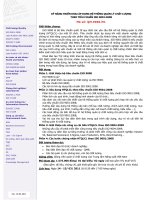
Flatness tolerance
The toleranced surface is contained between two parallel planes a distance t apart (see Figure 1 and also
ISO 1101:2004, Subclause 18.2).
Figure 1 — Example of a flatness tolerance
2
© ISO 2008 – All rights reserved
ISO 3302-2:2008(E)
The required flatness tolerances are given in Table 1.
Table 1 — Required flatness tolerances
Values in millimetres (unless indicated otherwise)
Nominal dimension
Class P
d
6
6.1
Class M
Class N
Above
Up to and including
Flatness tolerance, t
0
16
0,1
0,15
0,25
16
25
0,15
0,20
0,35
25
40
0,15
0,25
0,4
40
63
0,2
0,35
0,5
63
100
0,25
0,4
0,7
100
—
0,3 %
0,5 %
0,8 %
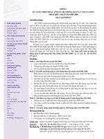
Parallelism tolerance
Sandwich structure (rubber between two metal plates)
The toleranced surface is contained between two parallel planes a distance t apart and parallel to the datum
surface D (see Figure 2 and also ISO 1101:2004, Subclause 18.9.3).
Figure 2 — Example of a parallelism tolerance: sandwich structure
© ISO 2008 – All rights reserved
3
ISO 3302-2:2008(E)
The required parallelism tolerances for a sandwich structure are given in Table 2.
Table 2 — Required parallelism tolerances: sandwich structure
Values in millimetres (unless indicated otherwise)
Nominal dimension
Class P
l
6.2
Class M
Class N
Above
Up to and including
Parallelism tolerance, t
0
40
0,15
0,2
0,35
40
100
0,2
0,35
0,5
100
250
0,35
0,5
0,8
250
—
0,15 %
0,25 %
0,4 %
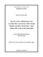
Extruded-product cut section (e.g. lathe-cut rings)
The toleranced surface is contained between two parallel planes a distance t apart and parallel to the datum
surface E (see Figure 3 and also ISO 1101:2004, Subclause 18.9.3).
Figure 3 — Example of a parallelism tolerance: extruded-product cut section
The required parallelism tolerances for an extruded-product cut section are given in Table 3.
Table 3 — Required parallelism tolerances: extruded-product cut section
Values in millimetres
Class P
Class M
Class N
Parallelism tolerance, t
0,1
4
0,2
0,3
© ISO 2008 – All rights reserved
ISO 3302-2:2008(E)
7
Perpendicularity tolerance
The toleranced face of the product is contained between two parallel planes a distance t apart and perpendicular
to the axis A (datum line) (see Figure 4 and also ISO 1101:2004, Subclause 18.10.4).
Figure 4 — Example of a perpendicularity tolerance
The required perpendicularity tolerances are given in Table 4.
Table 4 — Required perpendicularity tolerances
Values in millimetres (unless indicated otherwise)
Nominal dimension
Class P
d
8
8.1
Class M
Class N
Above
Up to and including
Perpendicularity tolerance, t
0
16
0,1
0,15
0,25
16
25
0,15
0,25
0,4
25
40
0,25
0,4
0,7
40
63
0,4
0,6
1,0
63
100
0,7
1,0
1,6
100
—
0,7 %
1,0 %
1,6 %
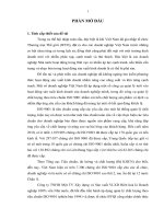
Coaxiality tolerance
Moulded products
The axis of each cylinder to which a tolerance frame is linked is contained in a cylindrical zone of diameter t C
or t F, respectively, coaxial with the datum axis D (see Figure 5 and also ISO 1101:2004, Subclause 18.13.2),
a distinction being made between
⎯
tolerances on fixed dimensions (subscript F), which are the dimensions defining a part of the moulded
product that are not affected by deforming influences like flash thickness or the lateral displacement of
mould parts (upper and lower parts or cores) (see Figure 5, diameters a and b);
© ISO 2008 – All rights reserved
5
ISO 3302-2:2008(E)
and
⎯
tolerances on closure dimensions (subscript C), which are the dimensions which can be altered by
variation in the flash thickness or lateral displacement of the mould parts (see Figure 5, diameter c).
Figure 5 — Example of coaxiality tolerances for a moulded product
The required coaxiality tolerances for moulded products are given in Table 5.
Table 5 — Required coaxiality tolerances for moulded products
Values in millimetres
Nominal dimension a
Class P
Class M
d
a
6
Class N
Coaxiality tolerance, t
Above
Up to and including
tF
tC
tF
tC
tF
tC
0
16
0,1
0,2
0,15
0,3
0,2
0,4
16
25
0,15
0,3
0,2
0,4
0,25
0,5
25
40
0,2
0,4
0,25
0,5
0,3
0,6
40
63
0,25
0,5
0,3
0,6
0,35
0,7
63
100
0,3
0,6
0,35
0,7
0,4
0,8
100
—
0,4
0,7
0,5
0,9
0,6
1,2
Coaxiality tolerances are determined by the largest dimension (see dimension a in Figure 5).
© ISO 2008 – All rights reserved
ISO 3302-2:2008(E)
8.2
Mandrel-supported extruded products
The centre of the circle to which the tolerance frame is linked is contained in a circle of diameter t concentric
with the centre of the datum circle A (see Figure 6 and also ISO 1101:2004, Subclause 18.3.1).
a
Applicable to each section only.
Figure 6 — Example of a coaxiality tolerance for mandrel-supported extruded products
The required coaxiality tolerances for mandrel-supported extruded products are given in Table 6.
Table 6 — Required coaxiality tolerances for mandrel-supported extruded products
Values in millimetres
Nominal dimension
Class P
d
8.3
Class M
Class N
Above
Up to and including
Coaxiality tolerance, t
0
10
0,2
0,4
0,6
10
16
0,25
0,5
0,8
16
25
0,35
0,6
1,0
25
40
0,40
0,8
1,3
40
63
0,5
1,0
1,6
63
100
0,6
1,3
2,0
100
—
0,8
1,6
2,5
Rotating parts
The tolerances on rotating parts shall not be described by a coaxiality tolerance but by a circular run-out
tolerance in accordance with ISO 1101:2004, Subclause 18.15.
Tolerance values shall be agreed between the interested parties.
© ISO 2008 – All rights reserved
7
ISO 3302-2:2008(E)
9
Positional tolerances
Positional tolerances may be specified, for example for the position of metal inserts in rubber products in
relation to an agreed point, e.g. the centre of a bushing (see ISO 1101:2004, Subclause 18.12).
Due to the variety of applications, positional tolerances shall be agreed between the interested parties.
8
© ISO 2008 – All rights reserved
ISO 3302-2:2008(E)
ICS 83.140.01
Price based on 8 pages
© ISO 2008 – All rights reserved