effects of growth temperature on carbon nanotube array thermal interfaces
Bạn đang xem bản rút gọn của tài liệu. Xem và tải ngay bản đầy đủ của tài liệu tại đây (317.66 KB, 4 trang )
Effects of Growth Temperature on
Carbon Nanotube Array
Thermal Interfaces
Baratunde A. Cola
Placidus B. Amama
Xianfan Xu
Timothy S. Fisher
e-mail: tsfi
School of Mechanical Engineering and Birck
Nanotechnology Center,
Purdue University,
West Lafayette, IN 47907
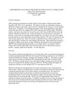
Due to their excellent compliance and high thermal conductivity,
dry carbon nanotube (CNT) array interfaces are promising can-
didates to address the thermal management needs of power dense
microelectronic components and devices. However, typical CNT
growth temperatures
͑ϳ
800°C
͒
limit the substrates available for
direct CNT synthesis. A microwave plasma chemical vapor depo-
sition and a shielded growth technique were used to synthesize
CNT arrays at various temperatures on silicon wafers. Measured
growth surface temperatures ranged from 500°C to 800°C. The
room-temperature thermal resistances of interfaces created by
placing the CNT covered wafers in contact with silver foil
(silicon-CNT-silver) were measured using a photoacoustic tech-
nique to range from approximately 7 mm
2
°C/ Wto19mm
2
°C/ W
at moderate pressures. Thermal resistances increased as CNT ar-
ray growth temperature decreased primarily due to a reduction in
the average diameter of CNTs in the arrays.
͓DOI: 10.1115/1.2969758͔
Keywords: carbon nanotube, thermal interface material, contact
thermal resistance, plasma CVD, low temperature, photoacoustic
Introduction
As semiconductor technology continues to advance, resulting in
progressive reductions of device feature sizes and expansion of
application opportunities, ensuring reliable operation has become
a growing challenge. The effective and efficient transfer of heat
from a chip to a heat sink is a vital step in meeting this challenge.
Advanced thermal management schemes that employ carbon
nanotube ͑CNT͒ arrays as interface materials have been suggested
as a means to dissipate high heat fluxes while maintaining low
chip temperatures ͓1–6͔. Under moderate pressure, CNT array
interfaces have been reported to produce thermal resistances as
low as 8 mm
2
°C/ W for arrays grown on one side of the interface
͓6͔ and as low as 4 mm
2
°C/ W for arrays grown on both sides of
the interface ͓4͔. However, the temperatures at which these CNT
array thermal interfaces were grown ͑Ͼ800° C͒ are incompatible
with the temperature-sensitive substrates used in standard semi-
conductor processes because the electrical performance of most
metal contacts and interconnects degrades when exposed to tem-
peratures up to 450°C for more than a limited time ͓7͔.
An insertable CNT array/foil material was recently suggested as
a way to apply CNT arrays to an interface without exposing the
mating materials to normal CNT growth temperatures, and resis-
tances as low as 10 mm
2
°C/ W were achieved under moderate
pressure ͓5͔. While this technique seems promising, progress in
low-temperature synthesis has been reported ͓7–10͔, and these
approaches may prove advantageous for their ability to offer
seamless integration into existing manufacturing processes; yet, to
the best of our knowledge, the literature reveals no studies on the
effects of decreased growth temperature on the thermal perfor-
mance of CNT array interfaces. In this Technical Brief, we report
on studies of thermal conduction through CNT array interfaces
grown at various temperatures, lower than those previously re-
ported.
Experimental Methods
Sample Fabrication. Microwave plasma chemical vapor depo-
sition ͑MPCVD͓͒11͔ and a shielded growth technique ͓10͔ were
used to synthesize vertically oriented CNT arrays on polished sili-
con wafers ͑560
m thick͒. Iron oxide ͑Fe
2
O
3
͒ nanoparticles
were deposited as a catalyst via a dendrimer template ͓12͔ on a
30 nm titanium barrier layer deposited atop the silicon. The sili-
con wafers were elevated ͑catalyst side facing away from the
plasma͒ on a 5.5 mm thick molybdenum puck by 1.2 mm thick
ceramic spacers, and the puck was set in the growth chamber on a
heated stage, as illustrated in Fig. 1. The stage temperature, T
stage
,
was set to 800° C, 700°C, 600°C , 500° C, 400° C, 300° C, and
200°C for different synthesis processes, and the catalyst was
heated in nitrogen ambient. The plasma power ranged
400–500 W, and the growth chamber’s pressure was 10 Torr. The
MPCVD process gases were hydrogen ͑50 SCCM ͑SCCM de-
notes cubic centimeter per minute at STP͒͒ and methane
͑10 SCCM͒, and growth was carried out for 20 min. Two separate
runs were performed at each growth condition to test repeatability.
A dual-wavelength pyrometer was aimed at the backside of the
silicon wafers to measure their temperature, T
pyrometer
, during
growth and to quantify the significance of additional heating due
to the plasma ͓13͔. Because of the relatively low intrinsic thermal
resistance of the silicon wafers, we expect the temperature at the
catalytic surfaces to be nearer T
pyrometer
than to T
stage
. Thus, we
will refer to T
pyrometer
as the “growth temperature.”
Sample Characterization. Figure 2 shows the scanning elec-
tron microscope ͑SEM͒ images that illustrate the results of CNT
arrays grown at different temperatures. Figure 2͑a͒ shows a verti-
cally oriented CNT array grown at 806° C. Figures 2͑b͒–2͑h͒ are
SEM images of equal magnification that illustrate the CNT mor-
phologies obtained from growth at 806– 506°C, respectively. The
CNTs in each sample were entangled near their free ends; yet, as
illustrated in Fig. 2͑a͒ and in the insets of Figs. 2͑c͒–2͑h͒, the bulk
of all CNT array samples were vertically oriented. A transmission
electron microscope ͑TEM͒ was used to examine wall structure
and revealed that nanotubes ͑as apposed to nanofibers͒ were
grown at each temperature. The bottom inset in Fig. 2͑h͒ contains
a TEM image of a CNT grown at 506° C. Table 1 summarizes the
morphological characteristics of the CNT arrays grown at each
temperature. The data are characteristic of the CNT arrays pro-
duced from two growth experiments at each temperature; hence,
redundant sample types were morphologically similar.
Raman spectroscopy was also used to characterize the CNT
arrays grown at each temperature. Well defined G ͑indicating well
ordered graphite͒ and D ͑indicating amorphous carbon and/or tube
defects͒ bands were observed, and the band intensity ratios I
G
/ I
D
were approximately 0.5 for each sample, indicating a similar qual-
ity of CNTs produced in this study. These results were somewhat
unexpected, as the quality of CNTs can depend strongly on growth
temperature; however, using the dendrimer-assisted catalysis tech-
nique, such control over CNT characteristics has been demon-
Contributed by the Heat Transfer Division of ASME for publication in the JOUR-
NAL OF HEAT TRANSFER. Manuscript received July 6, 2007; final manuscript received
June 17, 2008; published online September 2, 2008. Review conducted by Yogendra
Joshi.
Journal of Heat Transfer NOVEMBER 2008, Vol. 130 / 114503-1Copyright © 2008 by ASME
Downloaded 27 Jan 2009 to 128.210.126.199. Redistribution subject to ASME license or copyright; see />strated in arrays grown at various temperatures ͓6,9͔.
The CNT diameter ranges displayed in Table 1 include two
standard deviations from the mean, and the average is determined
from diameters within the ranges. As growth temperature de-
creased, the CNT diameters decreased as expected because of the
decrease in the mobility and/or aggregation of the catalyst nano-
particles ͓14͔. For each sample, SEM images were analyzed to
determine the density of CNTs by counting the number of CNTs
per unit area. The mean CNT array heights were also estimated
from SEM images. As growth temperature decreased, CNT den-
sity slightly decreased and mean array height decreased presum-
ably because of a lower reaction energy that impedes the CNT
growth process. At low growth temperatures, there is a decrease in
surface diffusion of the catalyst nanoparticles, carbon solubility in
the catalyst nanoparticles, and the diffusion of the carbon feed-
stock. All these factors play key roles during CNT growth espe-
cially the diffusion of carbon in the catalyst nanoparticles, which
has been widely suggested as the rate-determining step.
Thermal Resistance Measurement. The room-temperature
thermal resistances of silicon-CNT-silver interfaces grown via
MPCVD in the temperature range 806– 506 ° C have been mea-
sured using a photoacoustic ͑PA͒ technique described in detail by
Cola et al. ͓4͔. Due to its transient nature, the PA technique can be
used to measure multiple interface resistances as well as thermal
diffusivity within layered materials such as CNT array interfaces
͓4͔. The PA measurements were performed as a function of pres-
sure in a range applicable to the thermal management of micro-
processors, and relatively smooth silver foil ͑average peak-to-
valley surface height of 0.4
m͒ was used as the top interface
substrate to enable precise PA measurements ͓4͔.
Results and Discussion
The average results from several PA measurements on each
CNT array sample are illustrated in Fig. 3. Two separate samples
were fabricated at each growth temperature and thermally tested.
Figure 3 reveals exceptional consistency, both in terms of the
repeatability of redundant samples and in terms of trends with
respect to incremental variations in growth conditions. In fact, the
thermal resistance values of the redundant samples significantly
overlap considering the range of measurement uncertainty
͑Ϯ0.5 mm
2
°C/ W͒. After testing, the interfaces were separated,
and the CNTs remained well adhered to the silicon for each array,
independent of growth temperature. The one-sided CNT array to-
tal thermal interface resistances R measured in this study are the
sum of two local resistances ͑at the silicon-CNT interface and at
the free CNT tip-silver interface͒ plus the intrinsic resistance of
the CNT array. However, the local thermal resistances at the
silicon-CNT interfaces were measured using the PA technique to
be less than 1 mm
2
°C/ W and the resistances at the free CNT tip
interfaces were measured to be approximately equal to the thermal
resistances of the entire CNT array interface. Consequently, the
contact of the CNTs to their growth substrate and the effective
thermal conductivity of the CNT arrays had negligible effects on
the total thermal resistances. Previous works ͓3,4͔ have also dem-
onstrated that the thermal resistance at the interface to the free
CNT tips dominates the resistance of one-sided CNT array inter-
faces.
As clearly illustrated in Fig. 3, the total thermal resistance R of
the CNT array interfaces increases as CNT growth temperature
decreases. We attribute this performance characteristic to the CNT
array morphologies produced at different growth temperatures. As
the growth temperature was decreased, the associated decreases in
CNT density and average CNT diameter resulted in increased
thermal resistance at the interface. Because the average peak-to-
valley surface height of the silver foil ͑0.4
m͒ is much less than
the CNT array heights, we expect the variations in array height to
have little effect on thermal resistance in this study ͓2͔. For the
most part, the CNT density and diameter changed simultaneously
as array growth temperature changed; therefore, it is difficult to
isolate the individual effects of these morphological characteris-
tics on the associated changes in thermal interface resistance.
However, the CNT densities varied by a much lesser percentage
than the CNT diameters. Thus, we postulate that the changes in
CNT diameter governed the changes in thermal resistance. This
Fig. 1 Schematic of the sample configuration in the MPCVD
chamber „not to scale…
Fig. 2 SEM images of CNT arrays grown from 806° C to
506°C. „a… Vertically oriented CNT array grown at 806° C. „b…
Higher magnification image of CNTs grown at 806° C. „c… CNTs
grown at 737°C. The inset contains a lower magnification im-
age that illustrates vertically oriented CNTs „scale bar is 5
m….
„d… CNTs grown at 707°C. The inset contains a lower magnifi-
cation image „scale bar is 5
m…. „e… CNTs grown at 641°C „in-
set scale bar is 5
m…. „f… CNTs grown at 612°C „inset scale bar
is 1
m…. „g… CNTs grown at 524° C „inset scale bar is 1
m…. „h…
CNTs grown at 506° C. The top inset scale bar is 1
m. The
bottom inset contains a TEM image of a nanotube grown at
506°C „scale bar is 100 nm….
114503-2 / Vol. 130, NOVEMBER 2008 Transactions of the ASME
Downloaded 27 Jan 2009 to 128.210.126.199. Redistribution subject to ASME license or copyright; see />performance characteristic is best illustrated through closer ex-
amination of the growth temperature ranges 641– 524°C and
806–737° C, where the effects of CNT diameter are clearly dis-
tinguished.
When the CNT array growth temperature was reduced from
641°C to 612°C, the CNT density was slightly reduced, yet the
average CNT diameter remained constant. As illustrated in Fig. 3,
the thermal resistances produced by the 612° C arrays were ap-
proximately the same as the resistances produced by the 641° C
arrays. When the growth temperature was reduced from
612°C to 524°C, the average CNT diameter in the arrays de-
creased from approximately 15 nm to 10 nm, yet the CNT density
was approximately the same. In this case, the thermal resistances
produced by the 524° C arrays were larger than the resistances
produced by the 612°C arrays ͑Fig. 3͒. Additionally, when growth
temperature was reduced from 806°C to 737°C, the average
CNT diameter reduced while CNT density was approximately un-
changed, and as illustrated in Fig. 3, interface resistance increased
from the 806° C arrays to the 737° C arrays. These results are in
support of the CNT array’s average diameter having the dominate
effect on the measured thermal resistances in this study.
Because the local resistances at the free CNT end dominates the
total thermal resistances of the CNT array interface, changes in
total resistance are due to changes in resistance at the free CNT
end interface. At this interface, the characteristic contact size es-
tablished between an individual CNT and the opposing silver sub-
strate is at least an order of magnitude less than the room-
temperature phonon mean free path of CNTs ͑approximately
150 nm ͓15͔͒. Therefore, phonon transport through the contacts is
ballistic ͓16,17͔, and the total thermal resistance at the free CNT
ends interface, i.e., the total thermal resistance of the one-sided
CNT array interface, can be represented as
R = R
b
·
A
A
r
͑1͒
where R
b
is the thermal resistance at individual CNT contacts, A
r
is the real contact area established at the free CNT ends interface,
and A is the apparent contact area. We postulate that changes in
CNT diameter result in changes in A
r
, which affects the total
thermal resistance. Moreover, for the arrays in this study, we sug-
gest that CNT diameter affects A
r
primarily by influencing the
effective hardness of the CNT array, which determines the number
of CNTs that make contact with the opposing substrate. CNT cov-
erage in this study only varied by a small percentage; conse-
quently, as CNT diameter decreased, the total number of CNTs in
the arrays increased. Hence, the smaller diameter CNTs were
more closely packed ͑see Fig. 2͒. Presumably, as the smaller di-
ameter CNT arrays deformed in the interface under the applied
load, the close packing of CNTs promoted more tube-to-tube con-
tact within the arrays, providing increased support for individual
CNTs, such that the effective hardness of the arrays was increased
and A
r
was decreased, which is expected from traditional contact
theory in which A
r
is inversely proportional to hardness ͓18͔.
Therefore, as represented in Eq. ͑1͒, the total thermal resistance of
the CNT array interfaces increases as A
r
decreases.
Conclusions
The thermal resistances of CNT array interfaces grown in the
temperature range 806 – 506° C were measured to range from
7mm
2
°C/ Wto19mm
2
°C/ W, respectively. These values com-
parable favorably to previously reported CNT array thermal inter-
face resistances ͓1–6͔. Moreover, it has been demonstrated that
CNT arrays that provide good thermal interface conductance can
be grown at reduced temperatures that allow integration with sen-
sitive substrates ͑e.g., aluminum͒ that may be of particular interest
to the heat transfer community. Thermal resistance was measured
to increase as CNT array growth temperature decreased presum-
ably due to an increase in the stiffness of the CNT arrays that
reduced the amount of real contact area established in the inter-
face. Further experiments and extensive modeling are still re-
quired to fully understand the contact mechanics in and the ther-
mal transport through CNT array interfaces.
Acknowledgment
We gratefully acknowledge financial support from the National
Science Foundation under grant CBET-0646015. The lead author
is grateful for personal support from the Intel Foundation and the
Purdue University Graduate School.
Nomenclature
A
ϭ apparent contact area, m
2
A
r
ϭ real contact area at the free CNT end interface,
m
2
I
D
ϭ intensity of D band, a.u.
I
G
ϭ intensity of G band, a.u.
R ϭ total thermal resistance of CNT array interface,
mm
2
°C/ W
Table 1 CNT morphologies for arrays grown at different temperatures
T
stage
͑°C͒ 800 700 600 500 400 300 200
T
pyrometer
͑°C͒
806 737 707 641 612 524 506
Plasma power ͑W͒ 400 400 400 500 500 500 500
Mean CNT array height ͑
m͒
25 20 20 10 7 3 2
CNT density ͑%͒ 40–50 40–50 35–50 35–45 30–45 30–45 30–40
CNT diameter range ͑nm͒ 20–60 15–40 10–30 10–25 10–20 5–15 5–10
Average CNT diameter ͑nm͒ 40 30 23 15 15 10 8
Fig. 3 Total thermal resistance R as a function of pressure for
one-sided CNT array interfaces with arrays grown at various
temperatures
Journal of Heat Transfer NOVEMBER 2008, Vol. 130 / 114503-3
Downloaded 27 Jan 2009 to 128.210.126.199. Redistribution subject to ASME license or copyright; see />R
b
ϭ thermal resistance at individual CNT contacts,
mm
2
°C/ W
T
pyrometer
ϭ temperature of silicon surface facing the
plasma, °C
T
stage
ϭ temperature of the growth stage, °C
References
͓1͔ Xu, J., and Fisher, T. S., 2006, “Enhanced Thermal Contact Conductance
Using Carbon Nanotube Array Interfaces,” IEEE Trans. Compon. Packag.
Technol., 29͑2͒, pp. 261–267.
͓2͔ Xu, J., and Fisher, T. S., 2006, “Enhancement of Thermal Interface Materials
With Carbon Nanotube Arrays,” Int. J. Heat Mass Transfer, 49, pp. 1658–
1666.
͓3͔ Tong, T., Zhao, Y., Delzeit, L., Kashani, A., Meyyappan, M., and Majumdar,
A., 2007, “Dense Vertically Aligned Multiwalled Carbon Nanotube Arrays as
Thermal Interface Materials,” IEEE Trans. Compon. Packag. Technol., 30͑1͒,
pp. 92–100.
͓4͔ Cola, B. A., Xu, J., Cheng, C., Hu, H., Xu, X., and Fisher, T. S., 2007,
“Photoacoustic Characterization of Carbon Nanotube Array Thermal Inter-
faces,” J. Appl. Phys., 101, p. 054313.
͓5͔ Cola, B. A., Xu, X., and Fisher, T. S., 2007, “Increased Real Contact in
Thermal Interfaces: A Carbon Nanotube/Foil Material,” Appl. Phys. Lett., 90,
p. 093513.
͓6͔ Amama, P. B., Cola, B. A., Sands, T. D., Xu, X., and Fisher, T. S., 2007,
“Dendrimer-Assisted Controlled Growth of Carbon Nanotubes for Enhanced
Thermal Interface Conductance,” Nanotechnology, 18, p. 385303.
͓7͔ Melechko, A. V., Merkulov, V. I., McKnight, T. E., Guillorn, M. A., Klein, K.
L., Lowndes, D. H., and Simpson, M. L., 2005, “Vertically Aligned Carbon
Nanofibers and Related Structures: Controlled Synthesis and Directed Assem-
bly,” J. Appl. Phys., 97, p. 041301.
͓8͔ Boskovic, B. O., Stolojan, V., Khan, R. U. A., Haq, S., and Silva, S. R. P.,
2002, “Large-Area Synthesis of Carbon Nanofibers at Room Temperature,”
Nat. Mater., 1, pp. 165–168.
͓9͔ Hofmann, S., Ducati, C., Robertson, J., and Kleinsorge, B., 2003, “Low-
Temperature Growth of Carbon Nanotubes by Plasma-Enhanced Chemical Va-
por Deposition,” Appl. Phys. Lett., 83͑1͒, pp. 135–137.
͓10͔ Amama, P. B., Ogebule, O., Maschmann, M. R., Sands, T. D., and Fisher, T.
S., 2006, “Dendrimer-Assisted Low-Temperature Growth of Carbon Nano-
tubes by Plasma-Enhanced Chemical Vapor Deposition,” Chem. Commun.
͑Cambridge͒, 27, pp. 2899–2901.
͓11͔ Maschmann, M. R., Amama, P. B., Goyal, A., Iqbal, Z., Gat, R., and Fisher, T.
S., 2006, “Parametric Study of Synthesis Conditions in Plasma-Enhanced
CVD of High-Quality Single-Walled Carbon Nanotubes,” Carbon, 44, pp.
10–18.
͓12͔ Amama, P. B., Maschmann, M. R., Fisher, T. S., and Sands, T. D., 2006,
“Dendrimer-Templated Fe Nanoparticles for the Growth of Single-Wall Car-
bon Nanotubes by Plasma-Enhanced CVD,” J. Phys. Chem. B, 110, pp.
10636–10644.
͓13͔ Teo, K. B. K., Hash, D. B., Lacerda, R. G., Rupesinghe, N. L., Bell, M. S.,
Dalal, S. H., Bose, D., Govindan, T. R., Cruden, B. A., Chhowalla, M., Ama-
ratunga, G. A. J., Meyyappan, M., and Milne, W. I., 2004, “The Significance
of Plasma Heating in Carbon Nanotube and Nanofiber Growth,” Nano Lett.,
4͑5͒, pp. 921–926.
͓14͔ Meyyappan, M., Delzeit, L., Cassell, A., and Hash, D., 2003, “Carbon Nano-
tube Growth by PECVD: A Review,” Plasma Sources Sci. Technol., 12, pp.
205–216.
͓15͔ Shi, L., 2001, “Mesoscopic Thermophysical Measurements of Microstructures
and Carbon Nanotubes,” Ph.D. thesis, University of California, Berkeley.
͓16͔ Prasher, R., 2008, “Thermal Boundary Resistance and Thermal Conductivity
of Multiwalled Carbon Nanotubes,” Phys. Rev. B, 77, 075424.
͓17͔ Prasher, R., 2005, “Predicting the Thermal Resistance of Nanosized Constric-
tions,” Nano Lett., 5͑11͒, pp. 2155–2159.
͓18͔ Madhusudana, C. V., 1996, Thermal Contact Conductance, Springer-Verlag,
New York.
114503-4 / Vol. 130, NOVEMBER 2008 Transactions of the ASME
Downloaded 27 Jan 2009 to 128.210.126.199. Redistribution subject to ASME license or copyright; see />