measurement of in plane thermal conductivity of ultrathin films using micro raman spectroscopy
Bạn đang xem bản rút gọn của tài liệu. Xem và tải ngay bản đầy đủ của tài liệu tại đây (365.35 KB, 13 trang )
This article was downloaded by: [Purdue University]
On: 21 April 2014, At: 09:34
Publisher: Taylor & Francis
Informa Ltd Registered in England and Wales Registered Number: 1072954 Registered
office: Mortimer House, 37-41 Mortimer Street, London W1T 3JH, UK
Nanoscale and Microscale
Thermophysical Engineering
Publication details, including instructions for authors and
subscription information:
/>Measurement of In-Plane Thermal
Conductivity of Ultrathin Films Using
Micro-Raman Spectroscopy
Zhe Luo
a
, Han Liu
b
, Bryan T. Spann
a
, Yanhui Feng
c
, Peide Ye
b
, Yong P.
Chen
d
& Xianfan Xu
a
a
School of Mechanical Engineering and Birck Nanotechnology
Center, Purdue University, West Lafayette, Indiana
b
School of Electrical and Computer Engineering and Birck
Nanotechnology Center, Purdue University, West Lafayette, Indiana
c
School of Mechanical Engineering, University of Science and
Technology Beijing, Beijing, China
d
Department of Physics and Birck Nanotechnology Center, Purdue
University, West Lafayette, Indiana
Published online: 14 Apr 2014.
To cite this article: Zhe Luo, Han Liu, Bryan T. Spann, Yanhui Feng, Peide Ye, Yong P. Chen &
Xianfan Xu (2014) Measurement of In-Plane Thermal Conductivity of Ultrathin Films Using Micro-
Raman Spectroscopy, Nanoscale and Microscale Thermophysical Engineering, 18:2, 183-193, DOI:
10.1080/15567265.2014.892553
To link to this article: />PLEASE SCROLL DOWN FOR ARTICLE
Taylor & Francis makes every effort to ensure the accuracy of all the information (the
“Content”) contained in the publications on our platform. However, Taylor & Francis,
our agents, and our licensors make no representations or warranties whatsoever as to
the accuracy, completeness, or suitability for any purpose of the Content. Any opinions
and views expressed in this publication are the opinions and views of the authors,
and are not the views of or endorsed by Taylor & Francis. The accuracy of the Content
should not be relied upon and should be independently verified with primary sources
of information. Taylor and Francis shall not be liable for any losses, actions, claims,
proceedings, demands, costs, expenses, damages, and other liabilities whatsoever or
howsoever caused arising directly or indirectly in connection with, in relation to or arising
out of the use of the Content.
This article may be used for research, teaching, and private study purposes. Any
substantial or systematic reproduction, redistribution, reselling, loan, sub-licensing,
systematic supply, or distribution in any form to anyone is expressly forbidden. Terms &
Conditions of access and use can be found at />and-conditions
Downloaded by [Purdue University] at 09:34 21 April 2014
Nanoscale and Microscale Thermophysical Engineering, 18: 183–193, 2014
Copyright © Taylor & Francis Group, LLC
ISSN: 1556-7265 print / 1556-7273 online
DOI: 10.1080/15567265.2014.892553
MEASUREMENT OF IN-PLANE THERMAL CONDUCTIVITY
OF ULTRATHIN FILMS USING MICRO-RAMAN
SPECTROSCOPY
Zhe Luo
1
,HanLiu
2
, Bryan T. Spann
1
, Yanhui Feng
3
,PeideYe
2
,
Yong P. Chen
4
, and Xianfan Xu
1
1
School of Mechanical Engineering and Birck Nanotechnology C enter, Purdue
University, West Lafayette, Indiana
2
School of Electrical and Computer Engineering and Birck Nanotechnology Center,
Purdue University, West Lafayette, Indiana
3
School of Mechanical Engineering, University of Science and Technology Beijing,
Beijing, China
4
Department of Physics and Birck Nanotechnology Center, Purdue University, West
Lafayette, Indiana
We report a micro-Raman-based optical method to measure in-plane thermal conductivity of
ultrathin films. With the use of 20-nm-thick SiO
2
substrates that assure in-plane heat trans-
fer, sub-100-nm Bi films and Al
2
O
3
films as thin as 5 nm were successfully measured. The
results of Bi films reveal that phonon boundary scattering, both at the surface/interface and
at the grain boundaries, reduces in-plane lattice thermal conductivity. The measurements
of amorphous Al
2
O
3
films were accomplished using thin Bi film as a Raman temperature
sensor, and the results agree with the minimum thermal conductivity models for dielectrics.
Our work demonstrates that the micro-Raman method is promising for characterization of
in-plane thermal conductivity and phonon behaviors of thin-film structures if the Raman
temperature sensor material and substrate material are carefully selected.
KEY WORDS: micro-Raman, in-plane thermal conductivity, thin films, phonon boundary
scattering
INTRODUCTION
In the past decades, thermal transport in thin-film structures has been extensively
studied for applications such as thermal management in electronic devices [1, 2] and thin-
film thermoelectrics [3–6]. Thin-film boundaries and interfaces contain roughness and
defects that can scatter phonons efficiently [7, 8] and reduce the lattice thermal conduc-
tivity, which is advantageous for thermoelectrics to increase the thermoelectric figure of
merit ZT = σ S
2
T/k, where σ is the electrical conductivity, S is the Seebeck coefficient,
T is the absolute temperature, and k is the thermal conductivity. On the other hand, sup-
pressed thermal conductivity in nanoscale semiconducting or dielectric films reduces the
Manuscript received 23 August 2013; accepted 5 February 2014.
Address correspondence to Xianfan Xu, School of Mechanical Engineering, Purdue University, 585 Purdue
Mall, West Lafayette, IN 47907. E-mail:
Color versions of one or more of the figures in the article can be found online at www.tandfonline.com/umte.
183
Downloaded by [Purdue University] at 09:34 21 April 2014
184 Z. LUO ET AL.
heat removal efficiency in electronic devices whose power density increases at the pace
predicted by Moore’s law. Therefore, it is crucial to characterize the thermal conductivity
of thin-film-based devices to both evaluate their performance and reveal the underpinning
physical nature of heat transport.
Much effort has been devoted to measuring thin-film thermal conductivity. To mea-
sure the cross-plane thermal conductivity, the 3ω method [9–12] and the time-domain
thermoreflectance method [13–15] have been widely used. These are well-developed tech-
niques but are mostly limited to the measurement of cross-plane thermal conductivity,
because the characteristic size of the heat source (metal heater or focused laser spot)
is usually larger than the film thickness so that the cross-plane heat transfer into the
underneath layers or substrate is dominant. The thin-film in-plane thermal conductivity
measurement remains difficult [5] because the unfavorable heat flow into the substrate nar-
rows the choice of the substrate material and the measureable film thickness, usually to
hundreds of nanometers. The reported techniques include steady-state or transient (3ω)
heater wire method on suspended film [16] and microfabricated heater bridge [17]. Most of
these methods require very careful sample preparation and handling and sometimes com-
plicated modeling due to the irregular geometry involving additional structures such as a
heater.
In this work, we describe a noncontact, micro-Raman spectroscopy–based technique
that can potentially be applied to the in-plane thermal conductivity measurement of thin
films with sub-100-nm thickness. Micro-Raman systems tightly focus a laser beam on the
sample and collect the scattered photons whose frequency changes by a certain amount
due to photon–phonon inelastic scattering with the sample molecules or the periodic lattice
structure, which is known as Raman scattering. In our work, the same laser also induces
a heating effect, shifting the Raman peak due to bond softening and thermal expansion.
Temperature information can be obtained by measuring this heat-induced Raman peak shift.
Using a simple heat transfer model, the in-plane thermal conductivity of the sample can be
extracted. To ensure that the heat transfer is in-plane dominated and can be neglected in the
cross-plane direction, the in-plane dimension should be much larger than the cross-plane
dimension of the film. In terms of measuring in-plane thermal conductivity of thin films,
the micro-Raman method has been applied to a limited degree to mechanically exfoliated
2D films such as single-layer graphene [18–21] (thickness ∼0.35 nm). In this work, we
measured sub-100-nm-thick Bi films and used Bi films as Raman transducers to measure
Al
2
O
3
films. SiO
2
membranes with a 20-nm thickness were used as substrates. This allows
a selection of various types of thin-film materials to be measured while still maintaining
a very small total film thickness comparing with the lateral dimension. The low thermal
conductivity of SiO
2
(k = 1.4 W/mK [22]) minimizes the parasitic in-plane heat flow in
the substrate, which enhances the measurement sensitivity.
EXPERIMENTS AND MODELING
Sample Preparation
The thin-film substrates used were 20-nm-thick, 100 µm × 100 µmSiO
2
mem-
branes suspended on Si frames. The membranes were pure stoichiometric SiO
2
prepared by
sputtering from an SiO
2
target in an oxygen atmosphere. To measure the in-plane thermal
conductivity of Bi films, polycrystalline Bi films of thickness ranging from 20 to 145 nm
were thermally evaporated on the SiO
2
substrates with a vacuum pressure < 10
−6
Torr. The
Downloaded by [Purdue University] at 09:34 21 April 2014
IN-PLANE THERMAL CONDUCTIVITY 185
Raman shift in Bi produced by laser heating was used as the temperature sensor. To measure
the in-plane thermal conductivity of thin Al
2
O
3
films, 5- to 30-nm-thick Al
2
O
3
films were
deposited on the same SiO
2
membranes by atomic layer deposition (ALD) and then coated
with 20-nm-thick Bi films as the Raman temperature sensors because ALD-prepared Al
2
O
3
was amorphous and did not show Raman peaks. During each deposition process, a glass
substrate was coated simultaneously as a reference to measure the actual film thickness
by performing atomic force microscope scans after intentionally scratching the reference
thin-film sample.
Micro-Raman Measurement Method
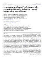
The experimental setup is illustrated in Figure 1a. A 632.8-nm HeNe laser was
focused by an Olympus 50 × objective (MPLN50x, Olympus America) at the center of the
sample placed in an open air environment at room temperature. This configuration suggests
a temperature distribution profile that is axisymmetric in the radial direction and uniform
in the vertical direction, because the film thickness is much smaller than its radial dimen-
sion. The excited Raman scattering was collected by a HORIBA LabRAM HR800 Raman
spectrometer (HORIBA Jobin Yvon, NJ, USA). The instrument has a spectral uncertainty
of 0.27 cm
−1
and peak fitting uncertainty of 0.02–0.07 cm
−1
. A power meter was placed
under the sample to measure the optical transmissivity T. At the entrance of the Raman
microscope, a beam splitter was used to direct the reflected light from the sample into a
power meter; by using a metallic mirror reference we obtained the reflectivity R of the
sample. A variable neutral density filter tuned the input laser power to change the sample
temperature and subsequently changed the Raman peak shift. With a calibration process,
the Raman peak shifts were interpreted to the temperature variations, which were then used
to model the heat transfer process.
The laser spot radius r
0
is a critical parameter for the in-plane thermal conductivity
calculation. To obtain r
0
, a knife-edge measurement based on Raman intensity was per-
formed using a sharp Si sample. A piezo-electric stage drove the Si edge to pass through
the focused laser beam, and the intensity of the Si Raman peak at 520 cm
−1
was recorded
as a function of the stage position. Raman scattering intensity is proportional to the inci-
dent laser power, so the Raman intensity as a function of stage position can be written as an
integral of the Gaussian laser intensity profile and fitted by a complementary error function:
(
x
)
=
∞
−∞
x−x
0
−∞
I
0
exp
−
x
2
+ y
2
r
2
0
dx
dy
= C
1 −
1
2
erfc
x − x
0
r
0
.(1)
Figure 1c shows the data and fitting result. It yields a laser focal spot radius r
0
=
500 ± 33 nm.
Heat Transfer Model
Under 1D assumption, the radial heat transfer equation for our thin-film laser heating
problem is described as follows:
1
r
d
dr
kr
dT
dr
+˙q = 0(2)
Downloaded by [Purdue University] at 09:34 21 April 2014
186 Z. LUO ET AL.
6789
0
2000
4000
6000
8000
10000
12000
Data
ERFC fit
Raman Intensity (a.u)
Distance ( m)
µ
Raman
spectrometer
HeNe laser
Edge
filter
Objective
Sample
Beam
splitter
Power meter
Variable ND
Power meter
Laser
Raman
scattering
Si
SiO
2
Sample film
Bi
(a)
(b)
(c)
Figure 1 (a) Schematic of the experimental setup. (b) Schematic of the sample structure. The sample film is
sandwiched between the Raman sensor Bi and the substrate SiO
2
. The film stack lies on an Si frame. For the
measurement of Bi films, there is no layer in between. (c) Laser spot size measurement results. The blue curve is
the complementary error function fitting of the data.
The heat source term ˙q is attributed to the absorbed laser power in Bi film, which spreads as
a Gaussian function along the in-plane direction and distributes uniformly in the cross-plane
direction:
˙q =
1 − R − T
t
P
πr
2
0
exp
−
r
2
r
2
0
,(3)
where t is the total thickness of the sample film stack, P is the total laser power, and r
0
is
the radius of the laser focal spot. Then the radial energy equation becomes
1
r
d
dr
k
eq
r
dT
dr
+
1 − R − T
t
P
πr
2
0
exp
−
r
2
r
2
0
= 0. (4)
Here, k
eq
stands for the equivalent in-plane thermal conductivity of the film stack:
k
eq
=
1
t
n
i=1
k
i
t
i
,(5)
where k
i
and t
i
are the thermal conductivity and the thickness of the ith layer, respectively.
At the edge of the film stack, the temperature is assumed equal to the room tempera-
ture T
0
, because the supporting s ilicon frame has a much higher thermal conductivity
(148 W/mK) than the film stack, thus acting as an efficient heat sink that immediately
lowers the boundary temperature to the ambient level.
Downloaded by [Purdue University] at 09:34 21 April 2014
IN-PLANE THERMAL CONDUCTIVITY 187
Because the experiments were performed in an open air environment, it is necessary
to evaluate the contributions of convective and radiative heat transfer. We estimated the 48-
nm Bi film sample with 100-µW incident power. According to our numerical analysis, the
area-weighted average temperature rise in the film is within 5 K, then the convective heat
transfer q
conv
= 2hA(T
avg
− T
0
) = 2 µW, where the convective heat transfer coefficient
h isassumedtobe20W/m
2
K and the sample area A = 100 × 100 µm
2
. In addition,
assuming that the temperature rise mainly occurs within a circular region of 20 µm radius
r, the radiative heat transfer can be estimated as q
rad
= 2σπr
2
(T
peak
4
− T
0
4
) = 0.78 µW,
with the peak temperature T
peak
= 340 K. It can be seen that both convective and radiative
heat transfer are much smaller and thus are neglected compared to the total absorbed laser
power on the order of 50 µW. With convective and radiative heat transfer neglected, the
temperature field can be solved from Eq. (4) as
T(r) = T
0
+
(1 − R − T)P
2πk
eq
t
1
2
Ei
−
r
2
r
2
0
− ln
r
r
0
−
1
2
Ei
−
r
2
b
r
2
0
− ln
r
b
r
0
,(6)
where Ei(x) is the exponential integral, r
b
is the equivalent radius of the square film,
which is the square root of A/π, where A is the sample area. According to our numeri-
cal calculations using both circular and square sample geometries, the approximation of
using circular geometry with equivalent radius resulted in less than 4% discrepancy in the
deduced in-plane thermal conductivity.
The temperature measured by the Raman laser beam is the Gaussian-weighted
average temperature:
T
Raman
=
∞
0
T(r)exp
−
r
2
r
2
0
rdr
∞
0
exp
−
r
2
r
2
0
rdr
.(7)
It can be shown that the Raman-measured temperature at the laser focal spot rises linearly
with laser power, and the temperature rising rate is a function of the equivalent thermal
conductivity of the sample film stack given in Eq. (5):
dT
Raman
dP
=
1 − R − T
2πk
eq
t
⎧
⎨
⎩
∞
0
1
2
Ei
−
r
2
r
2
0
− ln
r
r
0
exp
−
r
2
r
2
0
rdr
∞
0
exp
−
r
2
r
2
0
rdr
−
1
2
Ei
−
r
2
b
r
2
0
− ln
r
b
r
0
⎫
⎬
⎭
=
1 − R − T
2πk
eq
t
C
(
r
0
, r
b
)
.(8)
The above analysis is based on the 1D approximation that temperature distributes
uniformly in the cross-plane direction. To validate this assumption, we carried out 2D
numerical heat transfer calculation with a source term that decays exponentially in the
cross-plane direction to describe the actual laser absorption in the material and used the
dimensionless quantity T/(T
max
− T
0
) to evaluate the nonuniformity of the z-direction
temperature distribution at r = 0, where T is the temperature difference between the top
and the bottom of the film, T
max
is the maximum temperature in the entire film, and T
0
is the ambient temperature. We found that as film thickness increased to over 85 nm, the
Downloaded by [Purdue University] at 09:34 21 April 2014
188 Z. LUO ET AL.
dimensionless number became larger than 1% and we considered the cross-plane temper-
ature distribution to be noticeably nonuniform. Therefore, for films thicker than 85 nm, a
numerically solved 2D heat transfer model based on standard finite volume method was
implemented instead of 1D analytical model.
RESULTS AND DISCUSSION
To obtain accurate temperature data from Raman spectra, careful calibrations were
performed using a Linkam T95-HS heating stage (THMS720, Linkam, UK) for Bi films.
The Raman laser power was controlled at the minimum level to avoid excessive sample
heating while Raman scattering intensity was still strong enough to get accurate peak fitting.
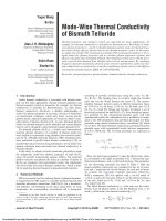
As seen in Figure 2a,TheA
1g
Raman peak of Bi at ∼97 cm
−1
showed good temperature
dependence. Figure 2b summarizes the calibration results of the A
1g
peak. It is noted that
for films thinner than 50 nm, the calibrated temperature coefficients were higher. This could
be caused by microstructural changes for different film thicknesses or nonuniform cross-
sectional strain in the film because the substrate is thin.
During experimental measurements of each Bi film, Raman spectra were taken under
different laser powers. Raman peak shifts were then converted to temperature changes using
the calibration coefficients. The measured temperature change varies with the laser power
linearly as predicted by Eq. (8) (see the inset of Figure 3 as an example). Hence, the in-plane
thermal conductivity of Bi films can be extracted by substituting the data slope into Eq. (8).
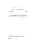
The results are shown in Figure 3. It is noted that the sample temperature increased gen-
erally by 40–50
◦
K at the laser irradiation center during the experiments; therefore, the
thermal conductivity results are the thermal conductivities of the average temperature of
the samples, which varies between 40 and 50
◦
K above the room temperature at the center
and the room temperature at the edge. The error bars are mostly attributed to the uncer-
tainty of the slope of Raman-measured temperature vs. laser power (dT
Raman
/dP), which
accounts for 50–70% of the total uncertainty in thermal conductivity; for those very thin
films, the uncertainty of film thickness (typically 1–4 nm) also accounts for about 30–40%
of the error. The other uncertainty sources, such as absorption and laser spot size, have
been taken into account as well. One may note that in previously reported graphene ther-
mal conductivity measurements using micro-Raman [20, 21], the total relative uncertainty
0
100
200
300
400
500
600
700
800
60 70 80 90 100 110 120
297 K
315 K
333 K
351 K
Raman Intensity (a.u.)
Wavenumber (cm
–1
)
97.062 cm
–1
96.629 cm
–1
96.266 cm
–1
95.988 cm
–1
E
g
A
1g
0 20406080100120140160
–0.030
–0.025
–0.020
–0.015
–0.010
Raman Peak Shift Coefficient (cm
–1
/K)
Bi Thickness (nm)
(b)(a)
Figure 2 (a) Raman spectra taken under different temperatures during the calibration of 85-nm-thick Bi sample.
Data are shifted vertically for a clearer view. The inset numbers denote the Lorentz fitted peak position of the A
1g
Raman mode. (b) Calibration results of Raman peak shift vs. temperature.
Downloaded by [Purdue University] at 09:34 21 April 2014
IN-PLANE THERMAL CONDUCTIVITY 189
5
6
7
8
9
10
11
12
13
14
15
0 20 40 60 80 100 120 140 160
In-plane Thermal Conductivity (W/mK)
Bi Film Thickness (nm)
µ
300
320
340
360
020406080
Temperature (K)
Absorbed Laser Power ( W)
Figure 3 In-plane thermal conductivity of Bi films. The inset plots the measured temperature vs. absorbed laser
power for the 85-nm film, and the black solid line is a linear fit. The inset pictures are atomic force microscope
images of the 24- and 37-nm film surfaces, which show different surface feature densities. The scale bars are all
1 µm.
is relatively large, usually ∼30% or higher, whereas in our work the uncertainty is less than
20%. This is mainly because the single-layer graphene absorbs only about 3% of the total
laser power, yielding large relative uncertainties in the final results even with a very small
uncertainty in determining the absorptivity. In contrast, our Bi films absorb 30–40% of the
total incident power, which is much greater than that of graphene; therefore, the relative
error of absorptivity is reduced, which gives more accurate in-plane thermal conductivity
values.
At the nanoscale, it is known that the lattice thermal conductivity can be dramatically
reduced as the characteristic length approaches the phonon mean free path (∼150 nm for
bulk Bi [23]). For films thicker than 100 nm, the measured in-plane thermal conductivity is
in agreement with that of bulk Bi (∼12 W/mK) reported by Gallo et al. [24], indicating that
the film thickness and grain size are comparable to or larger than the phonon mean free path.
As film thickness decreases, the in-plane thermal conductivity drops from about 12 W/mK
to less than 9 W/mK. This reduction can be attributed to phonon boundary scattering at
the film surface and interface, which restricts the phonon mean free path and subsequently
reduces the lattice thermal conductivity. It is also possible that the grain size varies for
different film thicknesses and further reduces the phonon mean free path. To take a closer
look into grain boundary scattering, X-ray diffraction experiments were performed on these
Bi samples using a Panalytical X’Pert Pro High Resolution X-ray diffraction (Panalytical
Inc., MA, USA) system with Cu Kα X-ray radiation of wavelength 1.54 Å. The classic
Scherrer equation [25] was used to estimate the sample grain size L:
L =
Kλ
B cos θ
,(9)
Downloaded by [Purdue University] at 09:34 21 April 2014
190 Z. LUO ET AL.
0
20
40
60
80
100
120
140
160
0 20 40 60 80 100 120 140 160
Grain Size (nm)
Film Thickness (nm)
0
50
100
150
200
10 20 30 40 50 60 70
Intensity (a.u.)
2 Theta (deg)
(003)
(006)
(009)
Figure 4 Grain sizes of Bi films calculated from the (003) peak of the X-ray diffraction data using Eq. (9). Grain
size uncertainty is ∼1 nm. The dashed line corresponds to where the grain size equals the film thickness. The inset
shows a typical X-ray diffraction pattern. The angle step size is 0.02
◦
.
where K is the Scherrer constant and is taken as 0.94, λ is the wavelength of the X-ray
radiation, B is the full width at half maximum of the diffraction peak, and θ is the Bragg
angle. Instrument broadening was considered to be minor due to small thickness and poly-
crystalline nature of the measured films, and the strain-induced broadening was likely to be
constant for thermally evaporated Bi thicker than 20 nm [26], so the Scherrer equation is
expected to give a good estimation of the grain s ize. From Figure 4 it is seen that the grain
size is roughly equal to the film thickness, which indicates that in the thinner films the
grain boundaries were more densely distributed in the lateral direction. In these Bi films,
the atomic level disorders at the grain boundaries act as phonon scattering sites and there-
fore reduce the lattice in-plane thermal conductivity together with phonon surface/interface
boundary scattering.
Surprisingly, an increase in the measured thermal conductivity is observed for films
with thicknesses of about 20 nm. Two samples with similar thicknesses were used to verify
this result. It was found that the surface asperities, which can scatter phonons, are prob-
ably responsible for the abnormal trend. As shown in the inset of Figure 3, the 24-nm
Bi film has much less surface features than the 37-nm film. For the ∼20-nm films and
other thicker films, the average number densities of asperities are 3.4 and 5–6 µm
−2
,
respectively, and the average asperity sizes (full width at half maximum) are 117 and
160–230 nm, respectively. The relatively smaller number density and size of these sur-
face features result in more specular and less diffusive phonon scattering at the sample
surface for thinner Bi films; therefore, the thermal conductivity reduction effect due to dif-
fusive phonon scattering is lower and causes higher in-plane thermal conductivity. The
observed in-plane thermal conductivity increase for the ∼20-nm films may provide an
insight into the roles of surface scattering and grain boundary scattering for reducing the in-
plane thermal conductivity of Bi films. The measured in-plane thermal conductivity value
of the ∼20-nm films, 11 W/mK, is close to those of the thickest Bi films measured in this
work, ∼12–13 W/mK. This means that grain boundary scattering contributes no more than
2W/mK of the total thermal conductivity reduction, and the low thermal conductivity of
the 37-nm film, ∼8W/mK, can be attributed to surface scattering. Therefore, surface scat-
tering may have an equal or even larger role than grain boundary scattering in reducing the
in-plane thermal conductivity of Bi films.
Downloaded by [Purdue University] at 09:34 21 April 2014
IN-PLANE THERMAL CONDUCTIVITY 191
0
1
2
3
4
5
6
7
8
0 5 10 15 20 25 30 35
In-plane Thermal Conductivity (W/mK)
Al
2
O
3
Film Thickness (nm)
Kinetic theory
prediction
Figure 5 In-plane thermal conductivity of Al
2
O
3
films. The dashed line corresponds to the kinetic theory predic-
tion by Eq. (10) under the assumption that the phonon mean free path is restricted to be equal to the interatomic
distance in amorphous solids.
We then used Bi film coated on Al
2
O
3
film as a Raman temperature sensor to mea-
sure the in-plane thermal conductivity of Al
2
O
3
films. Bi transducer film was deposited on
Al
2
O
3
instead of SiO
2
and therefore was calibrated separately and showed almost the same
calibration result as Bi-SiO
2
samples of similar thicknesses (both are −0.017 cm
−1
/K).
From Figure 5, the measured in-plane thermal conductivity values fall around 2 W/mK,
consistent with the experimental results reported by Stark et al. [27] This value is much
smaller than that of Al
2
O
3
crystals (over 30 W/mK), which can be understood in the
scope of minimum thermal conductivity model for dielectric crystals proposed by Slack
[28]. In this model, a crystal is assumed to have strong intrinsic atomic-scale disorder that
scatters the phonons frequently and consequently the phonon mean free path is limited to
the interatomic distance, yielding the minimum thermal conductivity that can be reached
in such disordered crystals. Because ALD-prepared Al
2
O
3
films are in amorphous states,
they resemble highly disordered Al
2
O
3
and are expected to exhibit the predicted minimum
thermal conductivity. A rough estimation can be carried out using the classic kinetic theory:
k =
1
3
C
v
vl, (10)
where C
v
is the volumetric heat capacity, v is the average phonon group velocity, and l is the
phonon mean free path and is taken as the equivalent interatomic spacing (the edge length
of the average cubic space that is occupied by each atom) for the amorphous Al
2
O
3
films.
Taking C
v
= 3.1 × 10
6
J/m
3
K[29], v = 11 km/s[30], l = 2.04 Å [28], Eq. (10) indicates
that the minimum thermal conductivity of Al
2
O
3
is 2.3 W/mK, shown as a dashed line in
Figure 5, which is in good agreement with the data. The minimum thermal conductivity
model developed by Cahill et al. [31] gives a similar value of ∼1.8 W/mK [32]. It is also
seen that the measurement uncertainty is quite significant for 10- and 5-nm films. This is
due to the reduction in the in-plane thermal conductance in the Al
2
O
3
film as film thickness
decreases. Because the Bi film used as the Raman temperature sensor has a much larger
thermal conductivity (∼10 W/mK) than the Al
2
O
3
film (and the SiO
2
substrate), the steady-
state temperature distribution becomes less sensitive to the Al
2
O
3
thermal conductivity for
very thin Al
2
O
3
films, yielding relatively large uncertainties.
Downloaded by [Purdue University] at 09:34 21 April 2014
192 Z. LUO ET AL.
CONCLUSIONS
In this work, a micro-Raman-based optical method to measure in-plane thermal con-
ductivity is presented and applied to Bi and Al
2
O
3
thin films. The measured results of Bi
films reveal that the phonon boundary scattering, both at the surface/interface and at grain
boundaries, may be the cause of the reduction of the in-plane lattice thermal conductiv-
ity. The measurements of Al
2
O
3
films were accomplished with the assist of Bi coatings
as Raman temperature sensors, and the measured in-plane thermal conductivity results
agree with proposed minimum thermal conductivity for dielectric solids. Our work demon-
strates that the micro-Raman method is capable of measuring in-plane thermal conductivity
of thin-film structures. In addition, a careful selection of the Raman temperature sensor
material and the substrate material is necessary. The most desirable scenario is that the
temperature sensor and substrate films have small thicknesses to assure 1D radial heat con-
duction, as well as low thermal conductivities to enhance heat flow through the sample
film.
FUNDING
We acknowledge support from the DARPA MESO program (Grant N66001-11-1-
4107). Y.F. is grateful for support from the Fundamental Research Funds for the Central
Universities of China (FRF-AS-12-002, FRF-TP-11-001B).
REFERENCES
1. D.G. Cahill, Heat Transport in Dielectric Thin Films and at Solid–Solid Interfaces, Microscale
Thermophysical Engineering, Vol. 1, pp. 85–109, 1997.
2. K.E. Goodson and Y.S. Ju, Heat Conduction in Novel Electronic Films, Annual Review of
Materials Science, Vol. 29, pp. 261–293, 1999.
3. R. Venkatasubramanian, E. Siivola, T. Colpitts, and B. O’Quinn, Thin-Film Thermoelectric
Devices with High Room-Temperature Figures of Merit, Nature, Vol. 413, pp. 597–602, 2001.
4. G. Chen, M.S. Dresselhaus, G. Dresselhaus, J.P. Fleurial, and T. Caillat, Recent Developments
in Thermoelectric Materials, International Materials Reviews, Vol. 48, pp. 45–66, 2003.
5. H. Böttner, G. Chen, and R. Venkatasubramanian, Aspects of Thin-Film Superlattice
Thermoelectric Materials, Devices, and Applications, MRS Bulletin, Vol. 31, pp. 211–217, 2006.
6. A. Shakouri, Recent Developments in Semiconductor Thermoelectric Physics and Materials,
Annual Review of Materials Research, Vol. 41, pp. 399–431, 2011.
7. G. Chen, Size and Interface Effects on Thermal Conductivity of Superlattices and Periodic Thin-
Film Structures, Journal of Heat Transfer, Vol. 119, pp. 220–229, 1997.
8. G. Chen, Thermal Conductivity and Ballistic-Phonon Transport in the Cross-Plane Direction of
Superlattices, Physical Review B, Vol. 57, pp. 14958–14973, 1998.
9. D.G. Cahill, Thermal Conductivity Measurement from 30–750 K: The 3ω Method, Review of
Scientific Instruments, Vol. 61, pp. 802–808, 1990.
10. S.M. Lee and D.G. Cahill, Heat Transport in Thin Dielectric Films, Journal of Applied Physics,
Vol. 81, pp. 2590–2595, 1997.
11. R. Venkatasubramanian, Lattice Thermal Conductivity Reduction and Phonon Localizationlike
Behavior in Superlattice Structures, Physical Review B, Vol. 61, pp. 3091–3097, 2000.
12. Z. Li, S. Tan, E. Bozorg-Grayeli, T. Kodama, M. Asheghi, G. Delgado, M. Panzer, A. Pokrovsky,
D. Wack, and K.E. Goodson, Phonon Dominated Heat Conduction Normal to Mo/Si Multilayers
with Period below 10 nm, Nano Letters, Vol. 12, pp. 3121–3126, 2012.
Downloaded by [Purdue University] at 09:34 21 April 2014
IN-PLANE THERMAL CONDUCTIVITY 193
13. W.S. Capinski, H.J. Maris, T. Ruf, M. Cardona, K. Ploog, and D.S. Katzer, Thermal-
Conductivity Measurements of GaAs/AlAs Superlattices Using a Picosecond Optical Pump-
and-Probe Technique, Physical Review B, Vol. 59, pp. 8105–8113, 1999.
14. D. Chu, M. Touzelbaev, K.E. Goodson, S. Babin, and R.F. Pease, Thermal Conductivity
Measurements of Thin-Film Resist, Journal of Vacuum Science & Technology B, Vol. 19, pp.
2874–2877, 2001.
15. Y.K. Koh, C.J. Vineis, S.D. Calawa, M.P. Walsh, and D.G. Cahill, Lattice Thermal Conductivity
of Nanostructured Thermoelectric Materials Based on PbTe, Applied Physics Letters, Vol. 94,
pp. 153101, 2009.
16. F. Völklein, H. Reith, and A. Meier, Measuring Methods for the Investigation of In-Plane
and Cross-Plane Thermal Conductivity of Thin Films, Physica Status Solidi A, Vol. 210, pp.
106–118, 2013.
17. A. Mavrokefalos, N.T. Nguyen, M.T. Pettes, D.C. Johnson, and L. Shi, In-Plane Thermal
Conductivity of Disordered Layered WSe
2
and (W)
x
(WSe
2
)
y
Superlattice Films, Applied
Physics Letters, Vol. 91, pp. 171912, 2007.
18. A.A. Balandin, S. Ghosh, W. Bao, I. Calizo, D. Teweldebrhan, F. Miao, and C .N. Lau, Superior
Thermal C onductivity of Single-Layer Graphene, Nano Letters, Vol. 8, pp. 902–907, 2008.
19. C. Faugeras, B. Faugeras, M. Orlita, M. Potemski, R.R. Nair, and A.K. Geim, Thermal
Conductivity of Graphene in Corbino Membrane Geometry, ACS Nano, Vol. 4, pp. 1889–1892,
2010.
20. W. Cai, A.L. Moore, Y. Zhu, X. Li, S. Chen, L. Shi, and R.S. Ruoff, Thermal Transport in
Suspended and Supported Monolayer Graphene Grown by Chemical Vapor Deposition, Nano
Letters, Vol. 10, pp. 1645–1651, 2010.
21. J.U. Lee, D. Yoon, H. Kim, S.W. Lee, and H. Cheong, Thermal Conductivity of Suspended
Pristine Graphene Measured by Raman Spectroscopy, Physical Review B, Vol. 83, pp. 081419,
2011.
22. Y.S. Touloukian, R.W. Powell, C.Y. Ho, and P.G. Klemens, Thermal Conductivity,TPRCData
Series, Vol. 2, Plenum, New York, 1970.
23. A.L. Moore, M.T. Pettes, F. Zhou, and L. Shi, Thermal Conductivity Suppression in Bismuth
Nanowires, Journal of Applied Physics, Vol. 106, p. 034310, 2009.
24. C.F. Gallo, B.S. Chandrasekhar, and P.H. Sutter, Transport Properties of Bismuth Single
Crystals, Journal of Applied Physics, Vol. 34, pp. 144–152, 1963.
25. J.I. Langford and A.J.C. Wilson, Scherrer after Sixty Years: A Survey and Some New Results in
the Determination of Crystallite Size, Journal of Applied Crystallography, Vol. 11, pp. 102–113,
1978.
26. A.A. Ramadan, A.M. El-Shabiny, and N.Z. El-Sayed, Size-Dependent Structural Characteristics
of Thin Bismuth Films, Thin Solid Films, Vol. 209, pp. 32–37, 1992.
27. I. Stark, M. Stordeur, and F. Syrowatka, Thermal Conductivity of Thin Amorphous Alumina
Films, Thin Solid Films, Vol. 226, pp. 185–190, 1993.
28. G.A. Slack, The Thermal Conductivity of Nonmetallic Crystals, in eds. F. Seitz and D. Turnbull,
Solid State Physics, Vol. 34, pp. 1–71, Academic, New York, 1979.
29. D.A. Ditmars, S. Ishihara, S.S. Chang, G. Bernstein, and E.D. West, Enthalpy and Heat-Capacity
Standard Reference Material: Synthetic Sapphire (α-Al
2
O
3
) from 10 to 2250 K, Journal of
Research of the National Bureau of Standards, Vol. 87, pp. 159–163, 1982.
30. J.M. Winey, Y.M. Gupta, and D.E. Hare, R-Axis Sound Speed and Elastic Properties of Sapphire
Single Crystals, Journal of Applied Physics, Vol. 90, pp. 3109–3111, 2001.
31. D.G. Cahill, S.K. Watson, and R.O. Pohl, Lower Limit to the Thermal Conductivity of
Disordered Crystals, Physical Review B, Vol. 46, pp. 6131–6140, 1992.
32. S.M. Lee and D.G. Cahill, Thermal Conductivity of Sputtered Oxide Films, Physical Review B,
Vol. 52, pp. 253–257, 1995.
Downloaded by [Purdue University] at 09:34 21 April 2014