parallel optical nanolithography using nanoscale bowtie aperture array
Bạn đang xem bản rút gọn của tài liệu. Xem và tải ngay bản đầy đủ của tài liệu tại đây (636.65 KB, 7 trang )
Parallel optical nanolithography using nanoscale
bowtie aperture array
Sreemanth M.V. Uppuluri, Edward C. Kinzel, Yan Li, and Xianfan Xu*
School of Mechanical Engineering and Birck Nanotechnology Center, Purdue University,
West Lafayette, IN 47906,USA
*
Abstract: We report results of parallel optical nanolithography using
nanoscale bowtie aperture array. These nanoscale bowtie aperture arrays are
used to focus a laser beam into multiple nanoscale light spots for parallel
nano-lithography. Our work employed a frequency-tripled diode-pumped
solid state (DPSS) laser (λ = 355 nm) and Shipley S1805 photoresist. An
interference-based optical alignment system was employed to position the
bowtie aperture arrays with the photoresist surface. Nanoscale direct-writing
of sub-100nm features in photoresist in parallel is demonstrated.
©2010 Optical Society of America
OCIS codes: (110.4235) Nanolithography; (220.4241) Nanostructure fabrication; (120.3180)
Interferometry.
References and links
1. S. Sun, and G. J. Leggett, “Matching the resolution of electron beam lithography by scanning near-field
photolithography,” Nano Lett. 4(8), 1381–1384 (2004).
2. M. M. Alkaisi, R. J. Blaikie, S. J. McNab, R. Cheung, and D. R. S. Cumming, “Sub-diffraction-limited patterning
using evanescent near-field optical lithography,” Appl. Phys. Lett. 75(22), 3560–3562 (1999).
3. Z. W. Liu, Q. H. Wei, and X. Zhang, “Surface plasmon interference nanolithography,” Nano Lett. 5(5), 957–961
(2005).
4. X. Shi, and L. Hesselink, “Mechanisms for enhancing power throughput from planar nano-apertures for near-
field optical data storage,” Jpn. J. Appl. Phys. 41(Part 1, No. 3B), 1632–1635 (2002).
5. K. Şendur, W. Challener, and C. Peng, “Ridge waveguide as a near field aperture for high density data storage,”
J. Appl. Phys. 96(5), 2743–2752 (2004).
6. E. X. Jin, and X. Xu, “Finite difference time domain studies on optical transmission through planar nano-
apertures in a metal film,” Jpn. J. Appl. Phys. 43(1), 407–417 (2004).
7. F. Chen, A. Itagi, J. A. Bain, D. D. Stancil, T. E. Schlesinger, L. Stebounova, G. C. Walker, and B. B.
Akhremitchev, “Imaging of optical field confinement in ridge waveguides fabricated on very-small-aperture
laser,” Appl. Phys. Lett. 83(16), 3245–3247 (2003).
8. L. Wang, S. M. V. Uppuluri, E. X. Jin, and X. Xu, “Nanolithography using high transmission nanoscale bowtie
apertures,” Nano Lett. 6(3), 361–364 (2006).
9. N. Murphy-DuBay, L. Wang, E. C. Kinzel, S. M. V. Uppuluri, and X. Xu, “Nanopatterning using NSOM probes
integrated with high transmission nanoscale bowtie aperture,” Opt. Express 16(4), 2584–2589 (2008).
10. Y. Kim, S. Kim, H. Jung, E. Lee, and J. W. Hahn, “Plasmonic nano lithography with a high scan speed contact
probe,” Opt. Express 17(22), 19476–19485 (2009).
11. W. Srituravanich, L. Pan, Y. Wang, C. Sun, D. B. Bogy, and X. Zhang, “Flying plasmonic lens in the near field
for high-speed nanolithography,” Nat. Nanotechnol. 3(12), 733–737 (2008).
12. E. X. Jin, and X. Xu, “Obtaining super resolution light spot using surface plasmon assisted sharp ridge nano-
aperture,” Appl. Phys. Lett. 86(11), 111106–111108 (2005).
13. Solvay Solexis Inc, “Fomblin Lubes – PFPE lubricants”,
14. Remcom Inc., FDTD Commercial Software Package, Version XFDTD 6.3.
15. H. Gai, J. Wang, and Q. Tian, “Modified Debye model parameters of metals applicable for broadband
calculations,” Appl. Opt. 46(12), 2229–2233 (2007).
16. P. B. Johnson, and R. W. Christy, “Optical constants of transition metals: Ti, V, Cr, Mn, Fe, Co, Ni and Pd,”
Phys. Rev. B 9(12), 5056–5070 (1974).
17. E. D. Palik, Handbook of Optical Constants of Solids (Academic Press, 1985).
18. M. Despont, J. Brugger, U. Drechsler, U. Dürig, W. Häberle, M. Lutwyche, H. Rothuizen, R. Stutz, R. Widmer,
G. Binnig, H. Rohrer, and P. Vettiger, “VLSI-NEMS chip for parallel AFM data storage,” Sens. Actuators 80(2),
100–107 (2000).
#123911 - $15.00 USD
Received 9 Feb 2010; revised 11 Mar 2010; accepted 15 Mar 2010; published 24 Mar 2010
(C) 2010 OSA
29 March 2010 / Vol. 18, No. 7 / OPTICS EXPRESS 7369
1. Introduction
Nano-optics-based lithography has the potential to be a low-cost alternative to other
nanofabrication techniques such as e-beam lithography. Many processes have been
demonstrated towards this end, including near-field optical microscopy (NSOM)-based
nanolithography [1], evanescent near-field optical lithography [2], and surface-plasmon
interference nanolithography [3]. Ridge nanoscale apertures of different shapes (C, H, bowtie)
have been shown to have a potential for optical nano-patterning via simulations [4–6] and also
experimental demonstration [7–10]. Figure 1 shows the schematic of a bowtie-shaped ridge
aperture. The unique property of ridge apertures enabling their application in nanolithography
is that these apertures support a propagating TE
01
mode when the incident laser light is
polarized across the gap. The energy of this mode is concentrated in the gap region and thus a
nanoscale light source is produced. The resolution of the light spot produced by these
apertures is limited only by the fabrication capability of producing a small gap in these
apertures. The radiation on the exit-plane of these apertures is however concentrated to within
a small distance, of the order of tens of nanometers from the exit-plane, beyond which the
light-spot increases significantly in size and decreases in intensity [6]. Thus using these
apertures for nanolithography and nano-patterning necessitates intimate contact between the
aperture exit-plane and the photoresist surface or accurate control of the separation distance to
within a few nanometers. These have been accomplished in different ways including allowing
the mask to ‘sit’ on the photoresist surface [8], using a closed-loop feedback mechanism [9],
applying normal force to maintain contact [10], and using air-pressure to levitate the mask to a
small height (~nm), similar to a computer hard-drive mechanism [11]. All the previous work
dealing with ‘writing’ patterns is however limited to using a single source.
Fig. 1. Bowtie-shaped ridge aperture.
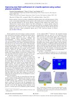
In this work we describe using a nanoscale bowtie aperture array for parallel nanolithography.
In addition to the optical issues related to the nanoscale bowtie aperture, we also report other
manufacturability considerations such as reducing the friction between the metal film and the
photoresist surface. We present an optical interference-based alignment system to establish
intimate contact between an array of apertures and the photoresist surface with minimum
friction between the two surfaces, thus facilitating parallel nano direct-writing.
2. Experiment setup
Figure 2 shows a schematic of the experiment setup. During the nanolithography process the
mask containing the bowtie aperture array is exposed to a frequency tripled diode-pumped
solid state (DPSS) UV laser beam (λ = 355nm) while the substrate is scanned using a
piezoelectric stage to create patterns. The laser beam is expanded; therefore all bowtie
apertures are exposed uniformly. The laser power intensity used is around 12.3 mW/cm
2
.
During the experiment the mask is loaded onto a two-axis tilt stage whereas the photoresist
sample is placed on top a high precision piezoelectric stage. The mask and photoresist
surfaces are then aligned to a high degree of parallelism using an interferometer system which
will be descried later. The mask is then moved into contact with the photoresist surface. This
minimizes the friction between the mask and the photoresist that allows the mask and the
#123911 - $15.00 USD
Received 9 Feb 2010; revised 11 Mar 2010; accepted 15 Mar 2010; published 24 Mar 2010
(C) 2010 OSA
29 March 2010 / Vol. 18, No. 7 / OPTICS EXPRESS 7370
photoresist to scan relative to each other to create patterns without damaging the mask or the
photoresist.
Fig. 2. Schematic of experiment setup.
The choice of the metal film for fabricating bowtie apertures is also important from the
standpoint of aperture performance [6,12] and from the point of view of obtaining smooth
films for maintaining a close contact between the aperture array and the photoresist surface. In
the past, the behavior of ridge apertures is studied extensively for aluminum films due to high
reflectivity and small skin-depth of aluminum in the visible and UV wavelength regime [8,9].
One of the main drawbacks of using aluminum for nano-aperture based lithography is the high
friction coefficient between the bare aluminum film and the photoresist surface. Also,
commonly available lubricant films [13] are incompatible with aluminum films. In addition,
obtaining aluminum films with surface roughness better than 1 nm has been found to be a
non-trivial task [10]. In this work we choose thermal PVD deposited chromium films which
are shown as a viable thin-film material for parallel nano-lithography so far as creating high
quality film is concerned. The optical performance of the apertures made in chromium is
shown to be comparable with those in aluminum as is discussed next.
3. Numerical simulations
We used finite-difference-time-domain simulation software [14] to numerically design the
bowtie apertures. The Modified Debye model [15] as shown in Eq. (1) is used to simulate the
permittivity (
ɶ
ε
) values of the metal films.
ɶ
0
.
1
s
j j
ε ε
σ
ε ε
ωτ ωε
∞
∞
−
= + +
+
(1)
At the process wavelength of λ = 355nm, the material model parameters are ε
s
= −23.591, ε
∞
=
8.785, τ = 2.3956 × 10
−16
s, σ = 1.19662 × 10
6
S/m for chromium and ε
s
= −595, ε
∞
= 1.01, τ =
1.03 × 10
−15
s, σ = 5.1235 × 10
6
S/m for aluminum [16,17]. The simulation model consists of
the metal film (Cr or Al) of thickness = 125 nm on top of a quartz substrate (n = 1.5646 @
355 nm). We chose a thickness of 125 nm since it is sufficient to screen background radiation.
The photoresist surface (Shipley S1805, n = 1.7433 @ 355nm) is placed at varying distances
from the aperture exit-plane, and the effect of the separation distance between the mask and
the photoresist on the obtainable resolution is studied, considering the existence of the
lubricant film (5 - 10 nm) and also that a small separation distance between the aperture and
the mask may exist during experiments. The bowtie aperture is excited by an incident plane
wave polarized across the gap of the aperture. The outline dimensions of the bowtie aperture
are a = b = 170 nm with a gap, s = 25 nm (see Fig. 1). These dimensions (a and b) are chosen
#123911 - $15.00 USD
Received 9 Feb 2010; revised 11 Mar 2010; accepted 15 Mar 2010; published 24 Mar 2010
(C) 2010 OSA
29 March 2010 / Vol. 18, No. 7 / OPTICS EXPRESS 7371
from numerical computation optimizations so that the higher order modes are not excited in
the bowtie aperture and the smallest obtainable spot size may be realized. The gap size is
chosen based on the fabrication resolution that can be achieved using an FIB machine at
Purdue University.
Figures 3(a) and 3(b) show the maximum electric field distribution in the E and H-planes
of bowtie apertures milled in aluminum and chromium films, respectively. For the results
shown in Fig. 3, a gap of 10 nm is used between the metal film and the photoresist surface. As
seen from the figure the magnitude of the electric fields and the corresponding spot sizes are
very close for the aluminum and chromium films.
Fig. 3. (a) Electric field distributions in the E and H planes for Aluminum bowtie aperture, (b)
Electric field distributions in the E and H planes for Chromium bowtie aperture.
4. Experimental details
We used optically flat (λ/20 @ λ = 633 nm) quartz substrates for preparing masks as well as
photoresist samples. The metal films are prepared by thermal evaporation of chromium on
quartz substrates at a deposition rate of around 0.5 Å/s. Figures 4(a) and 4(b) show
respectively the SEM and AFM images of the metal film. The roughness measured using
atomic force microscopy (AFM) is less than 1 nm over an area of 25 µm
2
. Apertures are
defined in the metal film using FIB milling (FEI Nova 200 Dual Beam FIB/SEM), with an
outline dimension of 170 nm × 170 nm (obtained from numerical simulation as discussed
above) and a gap size of 25 nm. The Cr film is then spin-coated with a 5-10 nm lubricant
Fomblin Z-Dol. The Z-Dol lubricant film is found to decrease the friction coefficient by a
factor of 3 and thus facilitates smoother motion of the mask relative to the photoresist surface.
The photoresist film (diluted S1805, at a dilution ratio of 1:6 in thinner type P) is spin-coated
on optically-flat quartz substrates. The RMS roughness of the photoresist films as measured
using atomic force microscopy is around 0.3 nm.
#123911 - $15.00 USD
Received 9 Feb 2010; revised 11 Mar 2010; accepted 15 Mar 2010; published 24 Mar 2010
(C) 2010 OSA
29 March 2010 / Vol. 18, No. 7 / OPTICS EXPRESS 7372
Fig. 4. Ultra-smooth chromium film prepared by the thermal PVD process. (a) SEM image, (b)
AFM topography image.
An important step in using the bowtie aperture array for nanolithography is aligning the mask
containing the bowtie aperture array with the photoresist-coated substrate. The goal is to
achieve high degree of parallelism between the mask and the photoresist surfaces as they are
brought to contact, thus reducing friction during their relative motion. To accomplish this task
we designed an optical interference-based alignment system. The tilt between the two surfaces
is initially adjusted by detecting the reflected laser spots from the mask and photoresist
surfaces using a quadrant photodiode (SPOT-9DMI, Optoelctronics Inc). By nulling the
signals generated by each reflected laser spot to within the measurement sensitivity, we
achieved a planar alignment in the order of 1 mrad between the two surfaces. Further
alignment is then achieved by using the fringes produced by the interference of the two
reflected spots. The width and the density of these fringes is a function of the relative tilt
between the two surfaces. By adjusting the tilt of the photoresist surface using a high-
precision piezoelectric stage the observed interference fringes can be reduced to zero over the
entire cross-section of the He-Ne laser spot. This ensures a planar parallelity of within 0.1
mrad. In an area of about 55 µm
×
55 µm where the bowtie array is fabricated, this implies a
planar alignment of about 5.5 nm in the x- and y-directions. Figure 5(a) shows the fringe
pattern observed experimentally for varying degrees of tilt between the mask and photoresist
surfaces. In the figure the horizontally inclined fringes correspond to those obtained from
interference of the reflected spots from the mask and photoresist surfaces whereas the
vertically inclined fringes are caused by a filter that is used to attenuate the brightness of the
He-Ne laser. Thus the vertical fringes have no bearing with the tilt misalignment between the
two surfaces. Figure 5(b) shows the fringe pattern from MATLAB simulations based on
geometric optics and interference theory. As seen from the figures the number of fringes and
the fringe density observed in experiment follow closely those predicted from MATLAB
simulations. As the present alignment system involves planar alignment using interference
fringes formed from the reflected spots from the mask and photoresist surfaces, we believe
that the alignment system does not impose any constraint on the maximum size of the bowtie
aperture array that can be used for parallel nanolithography. The largest patterning area on the
mask that is aligned to parallelity using the present interference system has been around 1.96
mm
2
. To improve the alignment accuracy for even larger patterning areas (> 1 cm
2
), a
possibility is using multiple He-Ne laser beams at different locations and adjusting the tilt
between the mask and photoresist surfaces to reduce the number of interference fringes at all
the locations simultaneously to zero.
In comparison to other parallel nano-patterning technologies such as AFM based millipede
system [18], we believe that the present system offers a simpler design for parallel
#123911 - $15.00 USD
Received 9 Feb 2010; revised 11 Mar 2010; accepted 15 Mar 2010; published 24 Mar 2010
(C) 2010 OSA
29 March 2010 / Vol. 18, No. 7 / OPTICS EXPRESS 7373
nanolithography. The main limitation of the present system is that it requires the photoresist
coated substrate to be transparent or semi-transparent to the He-Ne laser beam for allowing
the laser to pass through it. Thus the present alignment system needs to be modified for use
with photoresist coated silicon substrates.
Fig. 5. Interference fringes for varying degrees of tilt between the mask and
photoresistsurfaces. (a) Measured, (b) MATLAB simulations.
5. Experimental results
Figure 6(a) shows a plot of line widths produced in photoresist for varying scan speeds and
Fig. 6(b) shows the corresponding plot of line depths in the photoresist. As can be seen the
line width and depth decrease with increasing scan speeds. As mentioned earlier, expanding
the laser beam to expose an array of bowtie apertures causes significant reduction in the laser
power intensity, hence a relatively low laser intensity is used and the maximum scan speed in
our experiments is around 1 µm/s. Beyond this value the lines became too shallow and
irregular. The speed of nanopatterning may be improved by using a laser beam in conjunction
with other optical elements such as a diffractive optical element combined with a microlens
array such as a digital micro-mirror device (DMD), which allows exposing individual bowtie
apertures at fluence levels greater than that in the present system. Using such a system allows
switching ON/OFF bowtie apertures in the array selectively and thus offers a versatile system
for writing more intricate patterns.
The expected line-widths based on FDTD simulations are shown in Fig. 6(c) for a
separation distance of 10 nm between the mask and photoresist surfaces. These line widths are
based on threshold dose calculations (for a measured resist threshold dose of 5 mJ/cm
2
) and
the results are found to be close to those obtained from the experiment. The differences in the
exact line widths between the simulations and the experiments could be attributed to
ambiguities in the nature of the exact distance between the bowtie aperture and the photoresist
surface. The shape of the bowtie aperture obtained from FIB milling could also be different
from that used in the simulations. Figure 6(d) shows an AFM image of a line of about 90 nm
wide for a scan speed of 0.5 µm/s. The narrowest line width obtained is about 60 nm and is
shown in Fig. 6(e). However, as is evident, for such narrow line widths, the edge becomes
irregular and not repeatable. The two hot-spots from the bowtie aperture affect the
nanopatterning resolution during scanning in the x-direction (the x-axis direction as indicated
in Fig. 1), but not the other, which was confirmed in our experiments (all results shown here
correspond to scanning along the y-direction, the direction as indicated in Fig. 1). Thus for
nanopatterning involving scanning in both x and y-directions it is preferable to use a single-tip
nanoaperture instead of a bowtie (two-tip) aperture.
#123911 - $15.00 USD
Received 9 Feb 2010; revised 11 Mar 2010; accepted 15 Mar 2010; published 24 Mar 2010
(C) 2010 OSA
29 March 2010 / Vol. 18, No. 7 / OPTICS EXPRESS 7374
Fig. 6. Lines generated at different speeds – 0.2, 0.3, 0.4, 0.5, 0.6, 0.7, 0.8, 0.9µm/s. (a) width
of the lines, (b) depth of the lines, (c) XFDTD prediction of line widths, (d) AFM image of line
width ~90 nm, (e) AFM image of smallest line width of about 60 nm.
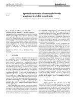
Figure 7 demonstrates patterning using an array of bowtie apertures in parallel. Figure 7(a)
shows an SEM image of a 2 × 2 bowtie array and Fig. 7(b) shows the AFM image of the
patterned photoresist film (letters BNC as in B
irck Nanotechnology Center of Purdue
University). The line width obtained during this experiment is around 85-90 nm for a scan
speed = 0.5 µm/s.
Fig. 7. Parallel writing using a 2 × 2 array of Bowtie apertures. (a) SEM image of the mask, (b)
AFM image of patterns produced in the photoresist.
6. Conclusions
In conclusion, we describe a nanoscale lithography system using light spots produced by a
bowtie aperture array. It includes an interference-based optical alignment system for aligning
the array of nanoscale bowtie apertures to a high degree of parallelity with a photoresist
coated substrate. Our experiments achieved parallel patterning, with a resolution in the order
of 85-90 nm with high degree of repeatability.
Acknowledgements
Support for this work provided by the National Science Foundation (NSF) (DMI-0707817,
DMI-0456809) and the Defense Advanced Research Project Agency (DARPA) grant
N66001-08-1-2037. Program Manager Dr. Thomas Kenny is gratefully acknowledged. The
authors also thank Luis M. Traverso for his help with the experiments.
#123911 - $15.00 USD
Received 9 Feb 2010; revised 11 Mar 2010; accepted 15 Mar 2010; published 24 Mar 2010
(C) 2010 OSA
29 March 2010 / Vol. 18, No. 7 / OPTICS EXPRESS 7375