focussed ion beam machined cantilever aperture probes for near field optical imaging
Bạn đang xem bản rút gọn của tài liệu. Xem và tải ngay bản đầy đủ của tài liệu tại đây (525.91 KB, 9 trang )
Journal of Microscopy, Vol. 229, Pt 3 2008, pp. 503–511
Received 26 September 2006; accepted 27 June 2007
Focussed ion beam machined cantilever aperture probes for
near-field optical imaging
E.X. JIN
∗
&X.XU
School of Mechanical Engineering, Purdue University, West Lafayette, IN, U.S.A.
Key words. Aperture, cantilever probe, FIB, micro-machining, NSOM.
Summary
Near-field optical probe is the key element of a near-
field scanning optical microscopy (NSOM) system. The key
innovation in the first two NSOM experiments (Pohl et al.,
1984; Lewis et al., 1984) is the fabrications of a sub-
wavelength optical aperture at the apex of a sharply pointed
transparent probe tip with a thin metal coating. This paper
discusses the routine use of focussed ion beam (FIB) to
micro-machine NSOM aperture probes from the commercial
silicon nitride cantilevered atomic force microscopy probes.
Two FIB micro-machining approaches are used to form a
nanoaperture of controllable size and shape at the apex of the
tip. The FIB side slicing produces a silicon nitride aperture
on the flat-end tips with controllable sizes varying from
120 nm to 30 nm. The FIB head-on drilling creates holes
on the aluminium-coated tips with sizes down to 50 nm.
Nanoapertures in C and bow tie shapes can also be patterned
using the FIB head-on milling method to possibly enhance the
optical transmission. A transmission-collection NSOM system
is constructed from a commercial atomic force microscopy
to characterize the optical resolution of FIB-micro-machined
aperture tips. The optical resolution of 78 nm is demonstrated
by an aperture probe fabricated by FIB head-on drilling.
Simultaneous topography imaging can also be realized using
the same probe. By mapping the optical near-field from a
bow-tie aperture, optical resolution as small as 59 nm is
achieved by an aperture probe fabricated by the FIB side
slicing method. Overall, high resolution and reliable optical
imaging of routinely FIB-micro-machinedaperture probes are
demonstrated.
Introduction
As one of scanning probe microscopy (SPM) techniques, near-
fieldscanningopticalmicroscopy(NSOM)usesanopticalprobe
Correspondence to: X. Xu. Tel: +1-765-496-5639; fax: +1-765-496-0539;
e-mail:
∗
Current address: Seagate Technology Research Center, Pittsburgh, PA, U.S.A.
to couple the evanescent components of the electromagnetic
field that decays exponentially from the samplesurface during
the tip–sample interaction. Near-field optical imaging with
sub-wavelength resolution down to a few tens of nanometers
has been demonstrated, far beyond the diffraction-limited
resolution that can be achieved by a conventional optical
microscopy, and therefore has been widely used in many
studies, suchas single moleculedetection (Betzig& Chichester,
1993), surface enhanced Raman spectroscopy (Ayars &
Hallen, 2000), nanofabrication (Smolyaninov et al., 1995),
high-density data storage (Betzig et al., 1992) and many other
subjects involving optical near-field (Dunn, 1999; Hecht et al.,
2000).
The near-field optical probe is the key element in an
NSOM system. For the aperture-type NSOM, the size of the
aperture at the apex of the probe determines the ultimate
optical resolution. In fact, the key innovation in the first
two independent NSOM experiments is the fabrications of a
sub-wavelength aperture at the apex of a transparent probe
tip (quartz rod, Pohl et al., 1984 and taped micro-pipette,
Lewis et al., 1984) with a thin metal coating. Nowadays,
tapered optical fibres andmicro-fabricated cantileveraperture
probes are commercially available benefiting from the rapid
development of various fabrication techniques for these two
kinds of aperture probes. However, the commercial NSOM
probes of high resolution (<50 nm) are normally marked
at a high price tag and are not reproducible. The probe
fabrication, particularly the fabrication of high-resolution
apertures of high quality in a reproducible, simple and low-
cost manner is of great interest for the development of NSOM
instrumentation.
There hasbeen a variety offabricationapproaches proposed
and investigated in the literature to form the sub-wavelength
aperture at the apex of a sharply pointed tip. Squeezing and
pounding a metal-coated tip against a hard surface (Pohl
et al., 1984; Saiki & Matsuda, 1999; Naber et al., 2002) is
a simple and straightforward method. Since it is a mechanical
wear process, the size and shape of the formed aperture
C
2008 The Authors
Journal compilation
C
2008 The Royal Microscopical Society
504
E.X. JIN AND X. XU
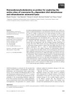
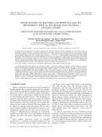
Fig. 1. SEM images of side view and top view of an aluminum-coated pyramidal tip on an AFM cantilever.
needs good control. Angled metal deposition (Betzig et al.,
1991) shadows the apex of the tip and forms the aperture
naturally in the deposition process. However, it is also a great
challenge in forming a controllable aperture size and shape.
Wet (Saiki et al., 1996) andsolid (Mulin et al., 1997; Bouhelier
et al., 2001) electrolytic demetallization approaches allow
reproducible formation of aperture in a more controllable
fashion but often requires an elaborated experimental set-up.
Laser-assisted selectivecorrosion(Haefliger &Stemmer, 2003)
is able to produce high-quality aperture probes by utilizing
aluminium corrosion in waterunder theevanescentfield. This
method only requires a simple total internal reflection optical
set-up, but it is limited to the selection of metal coating due to
the inherent aluminium corrosion mechanism. In the batch
fabrication process of cantilevered aperture probes, selective
reactive ion etching is often used to form a sub-wavelength
aperture, which involves multiple micro-fabrication steps and
various complicated tools (Mihalcea et al., 1996; Ruiter et al.,
1996; Minh et al., 2000; Choi et al., 2003).
Asahigh-precisionpatterningtechnique,focussedionbeam
(FIB)millinghasbeenintroducedtofabricateasub-wavelength
aperture at the apex of fibre-based (Muranishi et al., 1997;
Lacoste et al., 1998; Veerman et al., 1998) and cantilever-
based (Dziomba et al., 2001; Mitsuoka et al., 2001) probes. In
the FIB processing, an ion beam of high energy (typically 10–
100 keV) is focussed into sub-50 nm or smaller size, and
directed to impinge on the metal-coated tip. The metal
material at the apex of the tip is consequently removed to
form an aperture. The shape of the aperture fabricated by
FIB processing could be well defined by irradiation pattern
of the ion beam, and the size of the aperture could be
precisely controlled by the ion irradiation dose. It has also
been pointed out that the serial process of FIB technique
could be compensated by combining the FIB technique with
batchmicro-fabricationprocessofcantileverprobestoimprove
the throughput and reproducibility (Dziomba et al., 2001).
The major concern of FIB approach is the availability of
the expensive tool. Otherwise, it is the most desirable and
C
2008 The Authors
Journal compilation
C
2008 The Royal Microscopical Society, Journal of Microscopy, 229, 503–511
FOCUSSED ION BEAM MACHINED CANTILEVER APERTURE PROBES
505
high-precision approach to fabricate reliable aperture NSOM
probes with resolution better than 100 nm.
Thispaper discussestheroutine use ofFIBto micro-machine
NSOMaperture probesfromthe commerciallyavailablesilicon
nitride cantilevered atomic force microscopy (AFM) probes.
The complete fabrication procedure and details are explained.
The aperture probes fabricated by FIB side slicing and head-on
drilling methods are presented with controllable aperture size
ranging from 120 nm to 30 nm. Patterning of nanoapertures
with novel shapes by the FIB head-on drilling method is
also discussed as a potential approach to improve the power
throughput of an aperture probe. The high-resolution optical
imaging capability of routinely FIB-micro-machined aperture
probes is demonstrated by using the aperture probe as a
near-field collector in a transmission-collection NSOM system
constructed from a commercial AFM.
Aperture fabrication
To fabricate aperture NSOM probes, we start with the
standard silicon nitride cantilevered AFM probe, which are
commercially available (e.g. Veec, Santa Barbara, CA, USA).
The reason for using cantilevered AFM probes instead of fibre-
based probes includes the robustness, ease of handling and
ease of implementing in a standard AFM system. The silicon
nitride cantilevered probe we used contains four 0.6-μm-
thick V-shaped cantilevers at two lengths of 100 or 200 μm
and two widths of 10 or 20 μm. The nominal spring constants
of the four cantilevers are between 0.06 N m
−1
and 0.52
Nm
−1
depending on the dimensions. A pyramidal-shaped
hollowtip(about3μminheight,70
◦
openingangle,20–40nm
nominal tip radius and about 0.5 μm in side wall thickness) is
locatedat thevery endof thecantilever.Both thelarge opening
angle and high refractive index of silicon nitride (n = 2.35)
can contribute to the high power throughput of NSOM probes
fabricated from this type of AFM probes.
ThetipsideoftheAFM cantileverisfirstdepositedwithabout
an 86-nm-thick layer of aluminium film. It should be noted
that other metals can also be used as the coating material.
High deposition rate (10–20 Å s
−1
) is necessary to limit the
cantilever bending after aluminium coating and ensure a
pinhole-free film on the tip. Figure 1 shows SEM images of
side and top views of an aluminium-coated tip on the AFM
cantilever. The gold coatings on the back side of the cantilever
(opposite to the pyramid) are partially removed by FIB milling
(FEI DB 235dual beam machine, 30 keV Ga+ ions with10 pA
beam current) in order to let light transmitted through the
tip. As shown in the SEM image of Fig. 2, a window of about
0.65 × 0.65μm
2
is opened onthe back side ofthe tip. To make
an aperture opening at the apex of the tip, two FIB micro-
machining approaches, FIB side slicing and head-on drilling,
are employed.
The FIB side slicing method is the same as the technique
used to make a flat NSOM fibre probe (Veerman et al., 1998),
in whichion beamis irradiating fromthe sideof thetip ata 90
◦
angle from the normal. The aluminium at the very end of the
tip issliced awayuntil thesilicon nitridecore isexposedto form
a small aperture. 30 keV Ga
+
ions with 10 pA beam current is
used in the slicing process and the typical milling duration to
make a sub-100 nm aperture is less than 10 s. Figure 3 shows
the SEM images of the same tip asshown in Fig. 1after FIB side
slicing. It can be clearly seen that the sharp apex of the tip is
removed and left with a flat end of 280 nm in side length by
the ion beam irradiation. Asilicon nitride corein square shape
and of 80 nm × 80 nm in size is visible (the dark square in the
middle of the tip as shown in the lower right image in Fig. 3)
and can be used as a dielectric aperture for near-field imaging
inthe UVto near-IRwavelengthrange.The aluminium islands
on the side walls, possibly induced by debris on the tip before
aluminium deposition, are away from the aperture and do not
affect the imaging performance of the probe. The size of the
silicon nitride core can be controlled by varying the slicing
height from theapex. As shown in Figs 4(a)–(d), thefabricated
dielectric apertures have sizes varied from 120 nm down to
30 nm. The smallest aperture size that can be fabricated by
the FIB slicing method is determined by the apex size of the
original AFM tip, which is in the range of 20–40 nm for this
particular type probes. The shape of theaperture fabricated by
FIBside slicing isclosetosquaresince thetiphasthesymmetric
pyramidal shape.
FIBhead-ondrilling isirradiatingtheionbeam fromrighton
to the tip (perpendicular to the cantilever surface). Particular
milling patterns can be used. To irradiate ion beam exactly at
the apex of the tip, an ion beam image is taken first at high
Fig. 2. SEM image of the back side of a NSOM probe. A 0.65 × 0.65 μm
2
window is opened by FIB milling.
C
2008 The Authors
Journal compilation
C
2008 The Royal Microscopical Society, Journal of Microscopy, 229, 503–511
506
E.X. JIN AND X. XU
Fig. 3. SEM images of side view (first row) and top view (second row ) of the same tip shown in Fig. 1 after FIB side slicing. A silicon nitride core 80 nm by
80 nm in size is exposed after aluminum removal.
magnification (50–100 kX) followed by the exposure pattern
positioning. The exposure is then immediately executed to
limit the image drift. Coarse beam scan needs to be employed
to minimize the ion exposure damage to the aluminium film
during theion beam imaging.During the FIBhead-on drilling,
both the aluminium and silicon nitride core can be removed.
As shown in Fig. 5, a through hole in various sizes can be
formed at the tip apex. The smallest size of the aperture made
by this method is limited by the finite ion beam size and beam
tail effect. Thespot size ofion beam normally canbe controlled
to be as small as 10 nm at low current of 1 pA. However, it
is difficult to drill a sub-50 nm through hole directly at the
exact apex of the tip due to the image drift at extremely high
magnification. However, theadvantage of FIBhead-on drilling
is the ability to pattern nanoapertures in various shapes. In
addition to commonly used shape, for example, circular shape
(Muranishi et al., 1997; Lacoste et al., 1998) or rectangular
shape (Danzebrink et al., 1999; Dziomba et al., 2001), special
apertures inC andbow-tieshapes canbefabricatedbydefining
the desired exposure pattern of the ion beam as shown in
Fig. 6. In making this type of apertures, additional fabrication
steps need to be used, for example, an aluminium thin film is
coated after a small platform is created on the AFM tip by FIB
side slicing. These special shapes can possibly provide a high
transmissionthroughput(Shi etal.,2001; Sendur &Challener,
2003; Jin & Xu, 2004). (Characterizations of the throughput
of these apertures are currently underway.)
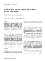
Resolution of FIB micro-machined NSOM probes
To characterize the optical resolution of fabricated NSOM
probes, an NSOM system is constructed. Figure 7 shows
the schematic diagram of this NSOM system operated in
the transmission-collection mode. The linearly polarized laser
sourceatλ= 633nm(heliumneonlaser)orλ =458nm(argon
ion laser) is used to illuminate a test sample from the bottom
C
2008 The Authors
Journal compilation
C
2008 The Royal Microscopical Society, Journal of Microscopy, 229, 503–511
FOCUSSED ION BEAM MACHINED CANTILEVER APERTURE PROBES
507
Fig. 4. SEM images of NSOM probes with a silicon nitride core in various size fabricated by FIB side slicing method.
by placing a prism underneath the sample. The test sample
contains FIB-patterned nanoapertures in aluminium on the
quartz substrate. The transmitted light from the aperture in
the sample is collected by the NSOM probe, which contains
a FIB-micro-machined nanoaperture at the apex as described
earlier. The soft contact between the probe and sample surface
is achieved by maintaining a small and constant normal force
based on the feedback of diode laser beam deflected on the
cantilever. A 20× long working distance objective (Mitutoyo
MPlan Apo SL 20×,NA= 0.28, WD = 30.5 mm, Kawasaki,
Kanagawa, Japan) and a set of lens, beam splitter and filters
are used to direct the collected light to a photo-multiplier tube
(PMT 9107B from Electron Tubes, Ruislip, UK). The photons
detectedbythePMTarecountedbyaphotoncounter(Stanford
SR400, Sunnyvale,CA, USA), whoseoutput (D/Aoutput port)
is connected to the AFM controller called AEM through a
low-voltage module (LVM). The photon counter needs to be
synchronized with the AFM scan. This is accomplished by
setting the photon counting period of each data point (T
set
)
and the internal time between two data points in the photon
counter (T
dwell
), as well as the delay time (T
delay
) after each
line in the AFM scan software. A 100-μm pinhole is placed in
the first image planeof the sample surface inorder to block the
straylightand toimprovetheimagingquality.Ahighprecision
piezo scanner is used for raster-scanning the aperture sample
and the optical signal described earlier is recorded to form an
NSOM image after scanning.
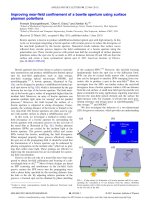
Figure 8(a) shows the SEM image of an NSOM probe
fabricated by FIB head-on drilling method. The SEM image is
taken acertain anglefrom thenormal ofthe tipso thedetails of
the aperture can be seen. The probe has an overall opening of
150 × 150 nm in size, but the silicon nitride core preserved in
the middle of the opening (the slightly brighter area in the
aperture), as a result of the different etching rate between
aluminium and silicon nitride, makes the effective aperture
size smaller as we will see from its optical resolution. Both the
AFM topography and NSOM images can be obtained after the
two-dimensional scan using this particular probe. Figure 8(b)
C
2008 The Authors
Journal compilation
C
2008 The Royal Microscopical Society, Journal of Microscopy, 229, 503–511
508
E.X. JIN AND X. XU
Fig. 5. SEM images of NSOM probes with an aperture in various size fabricated by FIB head-on drilling method.
showstheAFMtopographyofapairof160-nmholes separated
by80nm.TheinsetshowstheSEMimageoftheholepair.These
two holes areclearly separated inthe simultaneously recorded
NSOM image as shown in Fig. 8(c). The topographyimaging is
obtained because of any small aluminium protrusion near the
aperture rim or the silicon nitride core in the middle since the
tip made by the FIB head-on drilling process is not even (the
head-on milling does not produce an even surface). In fact,
there is an offset between the AFM and NSOM images as seen
in Figs 8(b) and (c), which further confirms this assertion. To
determine the optical resolution, a line scan is performed as
shown in Fig. 8(c), and the NSOM intensity profile along this
line scan is shown in Fig. 8(d). The measured 10–90% edge
resolution is 78 nm for thisaperture probe, whichis about 1/6
ofthe458nm illuminationwavelength.Thisopticalresolution
is also smaller than the overall size of the aperture, indicating
that the silicon nitride core determines the near-field optical
resolution for this type of NSOM probes.
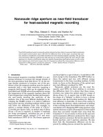
To characterize the NSOM probes of higher optical
resolutions,apoint-likelightsourceisneeded.Forthispurpose,
abow-tie–shapednanoaperture isfabricatedinthe aluminium
sample by FIB milling as shown in Fig. 9(a), which is able
to provide a nanoscale near-field spot with enhanced optical
transmission under proper illumination (Sendur & Challener,
2003; Jin & Xu, 2005, 2006). The bow-tie aperture has an
outline of about 216 nm × 248 nm and a 33-nm gap between
the two tips, and the size of the near-field spot produced by
the bow tie is about the same as the gap between the two
tips, 33 nm. The NSOM probe prepared by the FIB side slicing
method as shown in Fig. 9(d) is used to scan the optical near
field from this bow-tie aperture. This aperture tip has a silicon
nitride coreof 45nm × 45nm surrounded byaluminium. The
overall size of the tip end is 257 nm × 257 nm as measured
from the side of the tip (see the inset of Fig. 9(d)). A 458 nm
argon ion laser polarized across the bow-tie tips is used as the
illumination sourcein thismeasurement. Theobtained NSOM
C
2008 The Authors
Journal compilation
C
2008 The Royal Microscopical Society, Journal of Microscopy, 229, 503–511
FOCUSSED ION BEAM MACHINED CANTILEVER APERTURE PROBES
509
Fig. 6. SEM images of NSOM probes with a C and bowtie aperture at the
apex.
image is displayed in Fig. 9(b). Since the flat end of the probe
is larger than the size of the bow-tie aperture, no topography
information can be obtained. The size of the NSOM spot is
88nm×68nminFWHM.However,thislightspotisessentially
representing the convolutedcouplingbetweenthe optical near
field from the bow-tie aperture and the aperture probe (Jin &
Xu, 2006), meaning the actual light spot is smaller. The edge
resolution of this probe from the line scan profile is measured
to be59 nm,approximately thesum ofthe aperture size 45nm
and twice the skin depth of aluminium 6.5 nm at the 458 nm
wavelength.
Conclusions
Insummary,twoFIBmicro-machiningapproaches,sideslicing
andhead-ondrilling,are employedtofabricateapertureNSOM
probes. Thedetailed fabrication procedurehas beenpresented.
Both FIB approaches allow the precise control of the aperture
formation at the apex of the aluminium-coated tip. The FIB
side slicing is able to produce a silicon nitride aperture on
the flat-end tips with controllable sizes varying from 120 nm
to 40 nm. The FIB head-on drilling, on the other hand, is
capable to pattern nanoapertures of various shapes, including
circular, square, C and bow-tie shapes. To characterize the
optical resolution of FIB-micro-machined aperture tips, an
NSOM system using the aperture probe as the near-field
collector is constructed. By imaging a closely patterned pair
of nanoholes, the optical resolution of 78 nm is demonstrated
by an aperture probe fabricated by FIB head-on drilling.
The same probe is also able to obtain a topography image
simultaneously benefitting from the aluminium protrusion
on the aperture rim. By mapping the nanoscale optical near
field from a bow-tie aperture, optical resolution as high as
59 nm is achieved by an aperture probe fabricated by the
FIB side slicing method. These measurements demonstrated
high resolution and reliable optical imaging of the FIB-micro-
machined aperture probes.
Acknowledgements
The financial supports to this work by the National Science
Foundation and the Office of Naval research are gratefully
acknowledged.FabricationoftheNSOMprobesandtestsample
by FIB milling was carried out in the Center for Microanalysis
of Materials, University of Illinois, which is partially supported
by the U.S. Department of Energy.
References
Ayars, E.J. & Hallen, H.D. (2000) Surface enhancement in near-field
Raman spectroscopy. Appl. Phys. Lett. 76, 3911–3913.
Betzig, E., Trautman,J.K.,Harris, T.D.,Weiner,J.S.& Kostelak, R.L. (1991)
Breaking the diffraction barrier – optical microscopy on a nanometric
scale. Science 251, 1468–1470.
Betzig, E., Trautman, J.K., Wolfe, R., Gyorgy, E.M., Finn, P.L.,Kryder, M.H.
& Chang, C.H. (1992) Near-field magneto-optics and high density data
storage. Appl. Phys. Lett. 61, 142–144.
Betzig, E. &Chichester,R.J.(1993)Singlemolecules observed bynear-field
optical microscopy. Science 262, 1422–1425.
Bouhelier, A.H., Tamaru, J., G
¨
untherodt, H J., Pohl, D.W. & Schider, G.
(2001) Electrolytic formation of nanoapertures for scanning near-field
optical microscopy. Appl. Phys. Lett. 79, 683–685.
Choi,S.S.,Jung,M.Y.,Kim, D.W.,Kim,J.W.&Boo,J.H.(2003) Fabricationof
subwavelength-size aperture for anear-field optical probeusing various
microfabrication procedures. J. Vac. Sci. Technol. B. 21, 118–122.
Danzebroml, H.U., Dziomba, Th., Sulzbach, Th., Ohlsson, O., Lehrer, Ch.
& Frey, L. (1999) Nano-slit probes for near-field optical microscopy
fabricated by focused ion beams. J. Microsc. 194, 335–339.
Dunn, R.C. (1999) Near-field scanning optical microscopy. Chem. Rev. 99,
2891–2927.
Dziomba, T., Danzebroml, H.U., Lehrer, C., Frey, L., Sulzbach, T.& Ohlsson,
O. (2001) High-resolution constant-height imaging with apertured
silicon cantilever probes. J. Microsc. 202, 22–27.
Haefliger, D. & Stemmer, A. (2003) Fabrication of near-field optical
apertures in aluminum by a highly selective corrosion process in the
evanescent field. J. Microsc. 209, 150–154.
C
2008 The Authors
Journal compilation
C
2008 The Royal Microscopical Society, Journal of Microscopy, 229, 503–511
510
E.X. JIN AND X. XU
Fig. 7. Schematic view of the NSOM system in transmission-collection mode.
Hecht, B., Sick, B., Wild, U.P., Deckert, V., Zenobi, R., Martin, O.J.F. &
Pohl,D.W. (2000) Scanning near-fieldopticalmicroscopywithaperture
probes:fundamentalsandapplications.J.Chem.Phys. 112,7761–7774.
Held, T., Emonin, S., Marti, O. & Hollricher, O. (2000) Method to
produce high-resolution scanning near-field optical microscope probes
by beveling optical fibers. Rev. Sci. Instrum. 71, 3118–3122.
Jin, E.X. & Xu, X. (2004) FDTD studies on optical transmission through
planar nano-apertures in a metal film. Jpn. J. Appl. Phys. 43, 407–417.
Jin, E.X. & Xu, X. (2005) Obtaining super resolution light spot using
surface plasmon assisted sharp ridge nanoaperture. Appl. Phys. Lett.
86, 111106.
Jin, E.X. & Xu, X. (2006) Enhanced optical near field from a bowtie
aperture. Appl. Phys. Lett. 88, 153110.
Lacoste, Th., Huser, Th., Prioli, R. & Heinzelmann, H. (1998)
Contrast enhancement using polarization-modulation scanning near-
field optical microscopy. Ultramicroscopy 71, 333–340.
Lewis,A.,Isaacson,M.,Harootunian,A. & Muray,A.(1984)Development
of a 500Aspatial resolution lightmicroscope.Ultramicroscopy 13, 227–
232.
Mihalcea, C., Scholz, W., Werner, S., Munster, S., Oesterschulze, E. &
Kassing, R. (1996) Multipurpose sensor tips for scanning near-field
microscopy. Appl. Phys. Lett. 68, 3531–3533.
Minh, P.N., Ono, T. & Esashi, M. (2000) Microfabrication of miniature
aperture at the apex of SiO2 tip on silicon cantilever for near-field
scanning optical microscopy. Sens Actuators 80, 163–168.
Mitsuoka, Y., Niwa, T., Ichihara, S., et al. (2001) Microfabricated silicon
dioxidecantileverwithsubwavelengthaperture. J.Microsc.202,12–15.
Mulin, D., Courjon, D., Malugani, J.P. & Gauthier-Manuel, B. (1997) Use
of solid electrolytic erosion for generating nano-aperture near-field
collectors. Appl. Phys. Lett. 71, 437–439.
Muranishi, M., Sato, K., Hosaka, S., Kikukawa, A., Shintani, T. & Ito, K.
(1997) Control of aperture size of optical probes for scanning near-field
opticalmicroscopyusingfocusedionbeamtechnology.Jpn.J. Appl.Phys.
36, L942–L944.
Naber, A., Molenda, D., Fischer, U.C., Maas, H J., H
¨
oppener, C., Lu, N. &
Fuchs, H. (2002) Enhanced light confinement in a near-field optical
probe with a triangular aperture. Phys. Rev. Lett. 89, 210801.
Pohl, D.W., Denk, W. & Lanz, M. (1984) Optical stethoscopy:
image recording with resolution λ/20. Appl. Phys. Lett. 44, 651–
653.
Puygranier, B.A. & Dawson, P. (2000) Chemical etching of optical fibre
tips – experiment and model. Ultramicroscopy 85, 235–248.
Ruiter, A.G.T., Moers, M.H.P., van Hulst, N.F. & de Boer, M. (1996)
Microfabrication of near-field optical probes. J. Vac. Sci. Technol. B. 14,
597–601.
Saiki, T. & Matsuda, K. (1999) Near-field optical fiber probe optimized
for illumination–collection hybrid mode operation. Appl. Phys. Lett. 74,
2773–2775.
Saiki, T., Mononobe, S., Ohtsu, M., Saito, N. & Kusano, J. (1996)
Tailoringahigh-transmissionfiberprobeforphotonscanningtunneling
microscope. Appl. Phys. Lett. 68, 2612–2614.
Sendur,K.&Challener,W. (2003)Near-field radiationofbow-tieantennas
and apertures at optical frequencies. J. Microsc. 210, 279–283.
Shi, X., Hesselink, L. & Thornton, R. (2003) Ultrahigh light
transmission through a C-shaped nanoaperture. Opti. Lett. 28, 1320–
1322.
C
2008 The Authors
Journal compilation
C
2008 The Royal Microscopical Society, Journal of Microscopy, 229, 503–511
FOCUSSED ION BEAM MACHINED CANTILEVER APERTURE PROBES
511
Fig. 8. Characterizing the optical resolution of a NSOM aperture probe
fabricated by FIB head-on drilling method. (a) SEM image of the NSOM
probe showing a 150 nm × 150 nm aperture with a silicon nitride coer
in the middle, (b) AFM topography image of a pair of nanoholes in the
aluminum sample obtained by the NSOM probe (The inset is the SEM
image of the hole pair), (c) NSOM image of the nanoholes obtained by the
NSOM probe, and (d) intensity profile along the line scan on the NSOM
image showing the 10%-90% edge resolution is 78 nm. The scale bars in
(b) and (c) are 500 nm.
Fig. 9. The near-field ptical image (b) is collected from a bowtie
nanoaperture in an aluminum test sample shown in (a) using the FIB-
micromahined aperture probe as shown in (d). The inset of (d) is the side
SEM image of the same tip. The 10-90% edge resolution of this probe is
59 nm as shown in the optical profile (c) along the dash line in (b). The
scale bars in (a) and (b) are 250 nm.
Smolyaninov, I.I., Mazzoni, D.L. & Davis, C.C. (1995) Near-field direct-
write ultraviolet lithography and shear force microscopic studies of the
lithographic process. Appl. Phys. Lett. 67, 3859–3861.
Veerman, J.A., Otter, A.M., Kuipers, L. & van Hulst, N.F. (1998)
High definition aperture probes for near-field optical microscopy
fabricated by focused ion beam milling. Appl. Phys. Lett. 72, 3115–
3117.
Vollkopf,A.,Rudow,O.,Leinhos,T.,Mihalcea,C.&Oesterschulze,E.(1999)
Modified fabrication process for aperture probe cantilevers. J. Microsc.
194, 344–348.
Williamson, R.L. & Miles, M.L. (1996) Melt-drawn scanning near-field
optical microscopy probe profiles. J. Appl. Phys. 80, 4804–4812.
C
2008 The Authors
Journal compilation
C
2008 The Royal Microscopical Society, Journal of Microscopy, 229, 503–511