three dimensional mapping of optical near field of a nanoscale bowtie antenna
Bạn đang xem bản rút gọn của tài liệu. Xem và tải ngay bản đầy đủ của tài liệu tại đây (447.37 KB, 11 trang )
Three-dimensional mapping of optical near field
of a nanoscale bowtie antenna
Rui Guo*, Edward C. Kinzel, Yan Li, Sreemanth M. Uppuluri, Arvind Raman, and
Xianfan Xu
School of Mechanical Engineering and Birck Nanotechnology Center, Purdue University, West Lafayette, IN
47907,USA
*
Abstract: Ridge nanoscale aperture antennas have been shown to be a high
transmission nanoscale light source. They provide a small, polarization-
dependent near-field optical spot with much higher transmission efficiency
than circularly-shaped apertures with similar field confinement. This
provides significant motivations to understand the electromagnetic fields in
the immediate proximity to the apertures. This paper describes an
experimental three-dimensional optical near-field mapping of a bowtie
nano-aperture. The measurements are performed using a home-built near-
field scanning optical microscopy (NSOM) system. An aluminum coated
Si
3
N
4
probe with a 150 nm hole at the tip is used to collect optical signals.
Both contact and constant-height scan (CHS) modes are used to measure the
optical intensity at different longitudinal distances. A force-displacement
curve is used to determine the tip-sample separation distance allowing the
optical intensities to be mapped at distances as small as 50 nm and up to
micrometer level. The experimental results also demonstrate the
polarization dependence of the transmission through the bowtie aperture.
Numerical simulations are also performed to compute the aperture’s
electromagnetic near-field distribution and are shown to agree with the
experimental results.
©2010 Optical Society of America
OCIS codes: (180.4243) Near-field microscopy; (310.6628) Subwavelength structures,
nanostructures.
References and links
1. Z. Rao, L. Hesselink, and J. S. Harris, “High transmission through ridge nano-apertures on Vertical-Cavity
Surface-Emitting Lasers,” Opt. Express 15(16), 10427–10438 (2007).
2. A. Sundaramurthy, P. J. Schuck, N. R. Conley, D. P. Fromm, G. S. Kino, and W. E. Moerner, “Toward
nanometer-scale optical photolithography: utilizing the near-field of bowtie optical nanoantennas,” Nano Lett.
6(3), 355–360 (2006).
3. E. Jin, and X. Xu, “Obtaining subwavelength optical spots using nanoscale ridge apertures,” J. Heat Transfer
129(1), 37 (2007).
4. L. Wang, S. M. Uppuluri, E. X. Jin, and X. Xu, “Nanolithography using high transmission nanoscale bowtie
apertures,” Nano Lett. 6(3), 361–364 (2006).
5. K. Sendur, W. Challener, and C. Peng, “Ridge waveguide as a near field aperture for high density data storage,”
J. Appl. Phys. 96(5), 2743 (2004).
6. S. Park, and J. Won Hahn, “Plasmonic data storage medium with metallic nano-aperture array embedded in
dielectric material,” Opt. Express 17(22), 20203–20210 (2009).
7. A. Kinkhabwala, Z. Yu, S. Fan, Y. Avlasevich, K. Müllen, and W. Moerner, “Large single-molecule
fluorescence enhancements produced by a bowtie nanoantenna,” Nature Photonics 3, 654–657 (2009).
8. E. Jin, and X. Xu, “Enhanced optical near field from a bowtie aperture,” Appl. Phys. Lett. 88(15), 153110
(2006).
9. L. Zhou, Q. Gan, F. J. Bartoli, and V. Dierolf, “Direct near-field optical imaging of UV bowtie nanoantennas,”
Opt. Express 17(22), 20301–20306 (2009).
10. E. Lee, and J. Hahn, “Modeling of three-dimensional photoresist profiles exposed by localized fields of high-
transmission nano-apertures,” Nanotechnology 19(27), 275303 (2008).
11. L. Wang, and X. Xu, “Numerical study of optical nanolithography using nanoscale bow-tie-shaped nano-
apertures,” J. Microsc. 229(Pt 3), 483–489 (2008).
(C) 2010 OSA 1 March 2010 / Vol. 18, No. 5 / OPTICS EXPRESS 4961
#122970 - $15.00 USD Received 19 Jan 2010; revised 14 Feb 2010; accepted 17 Feb 2010; published 24 Feb 2010
12. E. Betzig, P. Finn, and J. Weiner, “Combined shear force and near field scanning optical microscopy,” Appl.
Phys. Lett. 60(20), 2484 (1992).
13. R. Toledo-Crow, P. Yang, Y. Chen, and M. Vaez Iravani, “Near field differential scanning optical microscope
with atomic force regulation,” Appl. Phys. Lett. 60(24), 2957 (1992).
14. K. Karrai, and R. Grober, “Piezoelectric tip sample distance control for near field optical microscopes,” Appl.
Phys. Lett. 66(14), 1842 (1995).
15. D. Tsai, and Y. Lu, “Tapping-mode tuning fork force sensing for near-field scanning optical microscopy,” Appl.
Phys. Lett. 73(19), 2724 (1998).
16. B. Hecht, H. Bielefeldt, Y. Inouye, D. Pohl, and L. Novotny, “Facts and artifacts in near-field optical
microscopy,” J. Appl. Phys. 81(6), 2492 (1997).
17. C. Jordan, S. Stranick, L. Richter, and R. Cavanagh, “Removing optical artifacts in near-field scanning optical
microscopy by using a three-dimensional scanning mode,” J. Appl. Phys. 86(5), 2785 (1999).
18. L. Aigouy, Y. De Wilde, and M. Mortier, “Local optical imaging of nanoholes using a single fluorescent rare-
earth-doped glass particle as a probe,” Appl. Phys. Lett. 83(1), 147–149 (2003).
19. L. Aigouy, P. Lalanne, J. P. Hugonin, G. Julié, V. Mathet, and M. Mortier, “Near-field analysis of surface waves
launched at nanoslit apertures,” Phys. Rev. Lett. 98(15), 153902 (2007).
20. B. Gady, D. Schleef, R. Reifenberger, and D. S. Rimai, “The Interaction between Micrometer-size Particles and
Flat Substrates: A Quantitative Study of Jump-to-Contact,” J. Adhes. 67(1), 291–305 (1998).
21. L. Verslegers, P. B. Catrysse, Z. Yu, J. S. White, E. S. Barnard, M. L. Brongersma, and S. Fan, “Planar lenses
based on nanoscale slit arrays in a metallic film,” Nano Lett. 9(1), 235–238 (2009).
22. L. Wang, and X. Xu, “High transmission nanoscale bowtie-shaped aperture probe for near-field optical imaging,”
Appl. Phys. Lett. 90(26), 261105 (2007).
1. Introduction
Nanoscale apertures are key elements for near-field optical engineering applications. They can
provide a light source that is not diffraction limited. However, circular or square apertures
with dimensions much smaller than the wavelength of light suffer from very low transmission.
Changing the aperture shape has been shown to dramatically improve their efficiency. One
example is nanoscale ridge aperture antennas [1,2]. A bowtie-shaped aperture can produce a
narrow peak intensity distribution with a FWHM (full-width at half maximum) of tens of
nanometers, and its peak intensity can be orders of magnitude higher than a circularly-shaped
aperture with a similar level of field confinement [3].
Bowtie ridge antennas have been used to provide focused spots for many applications
including nanoscale lithography fabrication [4], data storage [5,6], and single-molecule
fluorescence measurement [7]. Accurate measurements of the near-field optical intensity
distribution of these nano-apertures are important. A commonly used tool for such
measurements is near-field scanning optical microscopy (NSOM). Since the demonstration in
1984, NSOM has become an important tool for sub-wavelength resolution optical
measurement. Jin et al. measured the two-dimensional near-field intensity of a bowtie nano-
aperture [8]. Zhou et. al used NSOM to determine the relationship of antenna size and optical
field enhancement [9]. Lee et al. [10] obtained a three-dimensional optical distribution by
measuring photoresist profiles exposed by the localized fields of bowtie nano-apertures at
different gap distances. However, to the best of the authors’ knowledge, the full three-
dimensional near-field optical distribution as a function of the longitudinal direction using
NSOM has not been reported. According to numerical studies [11] on bowtie ridge nano-
aperture optical performance, the focused spot is a near-field source which decays
exponentially within the distance of wavelength. Three-dimensional measurements are
important to quantify the structure’s optical performance and for applications in which the
bowtie aperture and the sample are not in direct contact.
In a conventional illumination-collection NSOM system, a nanoscale aperture at the probe
tip is used to collect near-field signal. A two-dimensional image is obtained by scanning the
probe tip over the sample surface. In order to achieve three-dimensional near-field optical
measurement, the tip-sample distance needs to be controlled. There are several ways to
control the tip-sample distance in an NSOM system. One widely used method is to control the
distance based on feedback of tip-sample force. For example, oscillating the tip laterally to the
sample surface can be used to detect the damping produced by shear forces between the
NSOM tip and the sample [12,13]. Similar techniques, such as tuning forks with sharp tips
[14,15] and micro-cantilevers with optical detection feedback have also been used in
(C) 2010 OSA 1 March 2010 / Vol. 18, No. 5 / OPTICS EXPRESS 4962
#122970 - $15.00 USD Received 19 Jan 2010; revised 14 Feb 2010; accepted 17 Feb 2010; published 24 Feb 2010
conjunction with closed-loop control. These dynamic methods are restricted to a range of tens
of nanometers from the surface because the forces used for feedback are fundamentally short-
range. Another widely used method is the constant-height scan (CHS) [16,17], which is a
simpler method for three-dimensional optical near-field measurement. Aigouy et al.
developed a single fluorescent rare-earth-doped glass particle-assisted NSOM and measured
the three-dimensional local light intensities from nanoholes [18] and nanoslits [19] by using
CHS. The CHS method permits the tip-sample distance to be specified from tens of
nanometers to the micrometer range at which point the tip-sample interaction forces are
negligible. During scanning, the tip-sample distance feedback is turned off, which makes it
difficult to accurately control the tip-sample distance. This is especially true when the
separation is less than 100 nm because the attractive force between probe and sample can
make them jump to contact with each other. The jump-to-contact distance depends on several
parameters such as tip-sample surface energies, Hamaker constants. as well as environmental
factors [20].
In this paper, experimental results for the three-dimensional near-field optical and
polarization-dependent measurement of bowtie nano-aperture are presented. We employ
contact and CHS mode NSOM to investigate the three-dimensional near-field optical
transmission from of a bowtie nano-aperture. Bowtie optical distribution measurements at the
heights of 50 nm and up to micrometer level are achieved by carefully controlling sample
surface quality, probe tip topography, as well as scanning parameters. The response of the
bowtie nano-aperture is shown sensitive to the incident light polarization. Numerical studies
have shown that when incident light is polarized across the two tips of the bowtie, a well
confined near-field spot with high intensity is produced, however, the orthogonal polarization
produces a poor field confinement [3]. We compare our experimental results to finite-element
method (FEM) simulations of the near-field performance of the apertures. These are found to
be in good agreement.
2. Experimental Setup and Sample Preparation
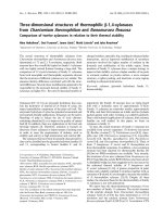
Figure 1 shows the schematic of our home-made illumination-collection mode NSOM setup.
It is based on a typical Atomic Force Microscopy (AFM) feedback control system. The
sample is placed on a three-dimensional piezoelectric stage (100 µm × 100 µm × 10 µm travel
range) and illuminated by a linear-polarized, focused argon-ion laser (λ = 457 nm). A half-
wave plate and a polarizer are used to control the polarization of the incident laser beam.
Because the light source is fixed with respect to the NSOM tip instead of the sample, it is
important to ensure the nano-aperture is uniform illuminated. In this experiment, the focused
Gaussian illumination spot size is around 5 - 10µm by using a Nikon 5 × objective. Over the
260 nm by 260 nm bowtie aperture, the illumination intensity varies around 0.1%. The
illumination distribution would need to be considered in order to measure larger samples. One
solution would be to fabricate the structure to be studied on a laser diode which could be
scanned relative to the probe [21].
(C) 2010 OSA 1 March 2010 / Vol. 18, No. 5 / OPTICS EXPRESS 4963
#122970 - $15.00 USD Received 19 Jan 2010; revised 14 Feb 2010; accepted 17 Feb 2010; published 24 Feb 2010
L
A
SE
R
Fig. 1. Schematic of home-made NSOM system. The illumination source is a λ = 457 nm
argon-ion laser. The feedback of NSOM head is based on the optical beam deflection
technique. The NSOM probe is an aluminum coated Si
3
N
4
probe with a 150 nm hole at the tip.
The pinhole has a size of 100 micron.
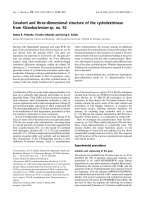
The bowtie aperture is milled using a focused ion beam (FIB) machine into a 150 nm thick
aluminum film evaporated onto an optically flat quartz substrate (flatness <λ/10). The aperture
has outline dimensions of 260 × 260 nm and a gap of 62 nm as shown in Fig. 2(A). Light
transmitted through the bowtie apertures is collected by a specially-fabricated NSOM probe
with a hole of about 150 nm diameter at its tip [shown in Fig. 2(B)]. The probe is a Veeco
Si
3
N
4
probe. It was coated with a 100 nm thick aluminum film on the front side prior to FIB
milling the hole at its apex. The nominal stiffness of the probe cantilever is 0.58 N/m. A 50 ×
objective lens is used to collect photons from the probe tip. A 100 µm pinhole is used as
spatial filter to select photons from the plane at probe tip, which are measured by a
photomultiplier tube. A flip mirror permits the experiment to be monitored by a CCD camera.
The AFM controller (RHK SPM100) provides typical closed-loop operation as well as manual
scanning without the feedback. This system has been used to successfully measure the near-
field optical intensity distribution of nano-aperture in contact mode while being controlled by
the normal force feedback based on the optical beam deflection technique [22].
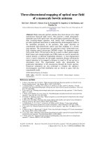
Fig. 2. (A) SEM image of the bowtie nano-aperture on a 150nm coated Al film. The aperture
has a size of 260 nm × 260 nm and has a gap of 62 nm. (B) SEM image of the NSOM probe.
The hole on the tip is around 150 nm in diameter. (C) Simulation model of bowtie nano-
antenna. Its dimensions used in simulation are fit to SEM image (A).
Numerical simulations are performed using a commercial frequency domain finite-element
method (FEM) package (HFSS from Ansoft LLC.) to calculate the near-field electromagnetic
distribution of the bowtie aperture. The simulation model includes the 150 nm Al film on top
of the fused silica substrate as shown in Fig. 2(C). The system is illuminated with a λ = 457
(C) 2010 OSA 1 March 2010 / Vol. 18, No. 5 / OPTICS EXPRESS 4964
#122970 - $15.00 USD Received 19 Jan 2010; revised 14 Feb 2010; accepted 17 Feb 2010; published 24 Feb 2010
nm plane-wave. The aperture outline dimensions used in calculations are fit to the SEM
images with the gap about 62 nm wide at the fused silica/aluminum interface and 134 nm at
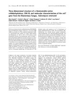
the top of the film. The calculated electric field distributions are shown in Fig. 3. Figures 3(A)
and 3(B) show that when the incident light is x-polarized it is focused to a spot at the center of
bowtie with two bright hot-spots at the tips. When the polarization is in the y-direction, the
highest field intensities occur at the edges of the aperture as shown in Fig. 3(C) and less light
overall passes through the center as shown in Fig. 3(D). A more detailed quantitative
comparison of the experimental and simulation results will be given below.
Fig. 3. Computed electric field distribution of bowtie aperture under x-polarized illumination
(A, B) and y-polarized illumination (C, D). The aperture has a size of 260 nm × 260 nm and a
gap of about 62 nm at the fused silica/aluminum interface and 134 nm at the top of the film.
The illumination is a λ = 457 nm plane-wave.
3. Experimental results and discussions
In the contact mode, the NSOM probe is kept in contact with the sample surface using a
closed-control loop to maintain a constant force (around 30 nN shown in Fig. 6) throughout
the scanning process. This method works well to capture photons close to the surface sample.
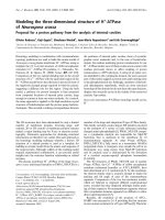
Figure 4(A) shows the near-field spot measured with contact mode scanning generated with
the incident laser linearly polarized in the x-direction. There are 64 × 64 pixels in each image
distributed over an area of 1 µm × 1 µm. The image was obtained with a scanning speed of
1.95 µm/s. Figure 4(B) shows the near-field spot measured in contact mode under y-polarized
illumination. The two figures show the bowtie aperture’s sensitivity to the polarization of the
incident light. Both the spot shape and size are different with a circular and focused spot is
A
Section 2
(C) 2010 OSA 1 March 2010 / Vol. 18, No. 5 / OPTICS EXPRESS 4965
#122970 - $15.00 USD Received 19 Jan 2010; revised 14 Feb 2010; accepted 17 Feb 2010; published 24 Feb 2010
observed under x-polarized illumination. This spot has a FWHM of around 157 nm and peak
intensity as high as 160 kHz in photon counts. For y-polarized illumination, multiple spots
located at the corners of the bowtie aperture can be seen, while the peak intensity is lower
(around 30 kHz). Considering a background noise level of 5 kHz, the peak intensity of the
spot with y-polarized illumination is about 6.2 times weaker than that with x-polarized
illumination.
Fig. 4. Near-field intensity distribution of bowtie aperture measured in the contact mode. The
scan area is 1µm × 1µm. The illumination laser is polarized along the x-direction (A) and y-
direction (B). Note the different intensity scales in the two figures.
Three-dimensional mapping of the near-field intensity can be acquired by turning off the
feedback and scanning the probe over the sample at a manually set height. This approach
allows the measurement of the optical fields at submicron to micrometer tip-sample distances.
First, the tip-sample distance needs to be calibrated by measuring the force-displacement
curve (F-z curve). Figure 5 shows the measured F-z curve by obtained when the NSOM probe
approaches the sample surface directly above the bowtie center position “A”, marked in
Fig. 4(a). The optical signal is acquired simultaneously and shown in Fig. 5. At a certain
distance from the surface, the probe snaps down into contact and the force change on the
cantilever is detected. The tip-sample contact point is located at around −50 nm as shown in
the abscissa of Fig. 5. This point (tip-sample contact position) is set as zero in the calibration
of tip-sample distance. Figure 6 shows the optical data when the light polarized in the y-
direction. In Fig. 5, the NSOM signal in the approaching direction (red line) has a peak of
around 160 kHz located at the tip-sample contact position. When tip-sample distance is larger,
especially when it is greater than 150 nm, the NSOM signal drops rapidly to less than 50 kHz.
In Fig. 6, the NSOM signal has a peak number of around 30 kHz. As the tip-sample distance
increases above 150 nm, the NSOM signal falls to 10 kHz. Figures 5 and 6 show that the light
intensity decays quicker when the light is polarized in the x-direction than when it is polarized
in the y-direction. When the tip-sample distance is larger than 200 nm, slight shifts in NSOM
signal are found around −0.6 µm and −0.35 µm in the NSOM curve showed in Figs. 5 and 6.
These are believed to result from Fabry-Perót electromagnetic interactions between NSOM
cantilever/probe and sample. Some of the light emitted from the aperture reflected between Al
coated cantilever and the Al bowtie sample surface to generate periodic interference when
their separation changes. This interaction will slightly increase the background optical noise.
In this work, we focus on near-field measurements in the range of 0 – 200 nm, where the
interference is not constructive. The black and blue lines in Figs. 5 and 6 are F-z curve and
NSOM signal, respectively, measured in retraction direction. After NSOM tip contacts with
the sample surface, the retraction needs to overcome tip-sample attractive force (around
−80nN in Fig. 5 and −140nN in Fig. 6). The force difference in Figs. 5 and 6 is likely caused
by the worn-out NSOM tip. This attractive force will bend the NSOM cantilever and slightly
shift the tip position, which results in the difference of NSOM signals collected at different
directions in Figs. 5 and 6.
(C) 2010 OSA 1 March 2010 / Vol. 18, No. 5 / OPTICS EXPRESS 4966
#122970 - $15.00 USD Received 19 Jan 2010; revised 14 Feb 2010; accepted 17 Feb 2010; published 24 Feb 2010
Fig. 5. NSOM signals and the F-z curve at the A position in Fig. 4(A). Data are collected at
different directions. Tip approach direction: green and red; tip retraction direction: black and
blue.
Fig. 6. NSOM signals and the F-z curve at the B position in Fig. 4(B). Data are collected at
different directions. Tip approach direction: green and red; tip retraction direction: black and
blue.
After calibration of the tip-sample distance using the F-z curve, a series of NSOM images
are collected at different heights using CHS. As in contact, the images are collected over an
area of 1 µm × 1 µm. There are 64 × 64 pixels in each image that are obtained with a scanning
speed of 1.95 µm/s. During a CHS, the position of the probe is fixed, while the sample is
located on a three-dimensional piezo-electric stage. The tip-sample distance is set by adjusting
sample height shown as abscissa in Figs. 5 and 6. The tip-sample distances for CHS
measurements are selected as 50 nm, 75 nm, 100 nm, 125 nm, 150 nm and 200 nm relative to
the “tip-sample contact point” as zero as shown in Fig. 5. The optical images obtained at
selected heights can be combined with the contact measurement to construct a three-
dimensional map of the bowtie optical near-field distribution.
Figure 7 shows the images at six different heights, obtained under x-polarized
illumination. In Fig. 7(A), a focused oval-shaped spot with a size of 213nm (x-direction) ×
229nm (y-direction) can be recognized. According to theory, the electromagnetic fields from a
nanoscale light source should decay with respect to distance exponentially. These images
show that the light rapidly diverges away from the bowtie aperture and the peak intensity also
decreases quickly. It is found that the spot almost disappears at 200nm-distance in Fig. 7(F)
which agrees with near-field optical theory. Figure 8 shows near-field distributions of the
(C) 2010 OSA 1 March 2010 / Vol. 18, No. 5 / OPTICS EXPRESS 4967
#122970 - $15.00 USD Received 19 Jan 2010; revised 14 Feb 2010; accepted 17 Feb 2010; published 24 Feb 2010
bowtie aperture when the polarization is in the y-direction. A multi-spot pattern can be
recognized in Figs. 8(A) and 8(B). This multi-spot distribution locates at corners of the bowtie
aperture which agrees with the simulation results shown in Fig. 3. It is found that the spot size
is bigger than the outline dimension of bowtie aperture which is believed to be caused by the
150nm-diameter NSOM tip. As the tip-sample distance becomes greater, the multi-spot
pattern disappears and peak intensity decreases from 30 kHz to a lower level around 10 kHz.
The spot intensity in y-polarized illumination decays slower than x-polarization. It agrees with
the simulation in Fig. 3.
Fig. 7. Constant-height scanning NSOM images at difference tip-sample distances: 50 nm, 75
nm, 100 nm, 125 nm, 150 nm and 200 nm in A - F, respectively. The laser polarization is in the
x-direction.
Fig. 8. Constant-height scanning NSOM images at different tip-sample distances: 50 nm, 75
nm, 100 nm, 125 nm, 150 nm and 200 nm in A - F, respectively. The laser polarization is in the
y-direction.
In order to further understand the three-dimensional near-field optical distribution, their
cross sections at different heights are plotted along with the corresponding simulation results.
Figures 9(A) and (B) show NSOM signal and computed electric field of Section 1 of Fig. 4(A)
at different tip-sample distances. For the 50 nm-distance curve in Fig. 9(A), the NSOM signal
has a peak of 132 kHz. This number drops to 49 kHz in the 200 nm-distance curve (a factor of
2.7). In Fig. 9(B), the corresponding theoretical peak intensity at the distance of 50 nm is 0.76
V/m. This number changes to 0.27 V/m at the distance of 200 nm (a factor of about 2.8). In
Fig. 9(B), the 50 nm-distance curve has two peaks at the positions x = 0.44 µm and 0.56 µm.
(C) 2010 OSA 1 March 2010 / Vol. 18, No. 5 / OPTICS EXPRESS 4968
#122970 - $15.00 USD Received 19 Jan 2010; revised 14 Feb 2010; accepted 17 Feb 2010; published 24 Feb 2010
The two peaks come from the bowtie’s two tips. The experimental results do not show the two
peaks because the 150 nm-diameter aperture at the NSOM scanning tip is not small enough to
resolve these two peaks. Figures 9(C) and 9(D) shows the NSOM signal and the computed
electric field along Section 2 of Fig. 4(A) at different tip-sample distances. The peak intensity
also drops rapidly when increasing tip-sample distance. In Fig. 9(C), an increase in the noise
level could be found at the range of x = 0.8 µm to x = 1 µm. This increase is caused by light
leaking around the edge of the NSOM cantilever. When NSOM tip is scanning over the
bowtie sample, the photons from the passing through probe aperture are collected and counted
by the PMT, while all the other photons coming from the bowtie are blocked by NSOM
cantilever. The fact that the cantilever is much wider than the probe has a significant role for
maintaining a low noise level in the measurement. During the data acquisition, the cantilever
can scan over a region large enough so that the line of sight from the bowtie aperture to the
PMT is not blocked by the cantilever. This introduces an additional small noise level change
at different locations. When data is acquired in contact mode, the NSOM tip collects signals
according to the topography of the sample surface. This changes the interrogation volume so
that it does not necessarily correspond to the simulation data from the bowtie apertures exit
plane (z = 0). The FWHM of the near-field spot size after Gaussian fits of Fig. 9 are shown in
Table 1. When the tip-sample distance increases from contact to a distance of 200 nm, the
FWHM of the optical signal in Fig. 9(A) increases about 1.9 times from 157 nm to 305 nm
while the corresponding FWHM of simulated aperture response from Fig. 9(B) increases
about 2.2 times from 246 nm to 539 nm. For Fig. 9(C), its FWHM increases from 169 nm to
499 nm (3.0 times) while the simulated data increases from 137 nm to 403 nm (2.9 times).
The differences between the measured and calculated FWHM sizes are likely due to the
differences in the dimensions of the bowtie geometries used in the calculations vs. in the
experiments.
Fig. 9. Experimental (A,C) and theoretical (B,D) intensity distribution along sections 1 and 2 of
Fig. 4(A), respectively, at different heights for laser polarization in the x-direction.
(C) 2010 OSA 1 March 2010 / Vol. 18, No. 5 / OPTICS EXPRESS 4969
#122970 - $15.00 USD Received 19 Jan 2010; revised 14 Feb 2010; accepted 17 Feb 2010; published 24 Feb 2010
Table 1. Measured FWHM of near-field spot at different heights
a
X FWHM(nm)
Y FWHM(nm)
Height(nm)
Exp.
Sim.
Exp.
Sim.
Contact/Z = 0
157
246
169
137
50
213
342
229
194
75
219
383
277
229
100
245
418
368
b
266
150
292
481
433
b
339
200
305
539
499
b
403
a
From Gaussian fits of
Fig. 9
.
b
These Gaussian fits are done in the region of y = 0~0.8µm to reduce
noise effect.
Figure 10 shows the theoretical and experimental near-field distributions at different tip-
sample distances under y-polarized illumination. Figure 10(A) shows the NSOM signal along
section 3 of Fig. 4(B) at different tip-sample distances. The peak signal in the 50 nm-distance
curve is 23 kHz. As the tip-sample distance increases to 150 nm, there is little change of the
peak intensity, which is 21 kHz. As the distance increases to 200 nm, the peak intensity drops
slightly to 18 kHz. The total drop in the NSOM signal is about 15%. In Fig. 10(B), the
corresponding calculated peak intensity at 50 nm is 0.76 V/m. The peak intensities for 75 nm,
100 nm, 150 nm and 200 nm are 0.75, 0.73, 0.64 and 0.56 V/m, respectively. The total drop
from 50nm to 200nm is about 26%. Figure 10(C) shows NSOM signal of section 4 of
Fig. 4(B) at different tip-sample distances from 50 nm to 200 nm. Similarly, the decrease of
the peak intensity with the increasing tip-sample distance can be found from both
experimental and simulation results. When the tip-sample distance increases from 50nm to
200 nm, the peak intensity of the optical signal in Fig. 10(C) decreases about 24% from 23
kHz to 17.5 kHz while the corresponding simulated response from Fig. 10(D) decreases about
44% from 1 to 0.56 V/m. Multi-peak shape is shown in contact, 50 nm, 75 nm and 100 nm
curves in Fig. 10(C). The same patterns can be found in the corresponding curves in
Fig. 10(D). For example, the 50 nm-distance curve in Fig. 10(C) has two peaks at the
positions x = 0.49 µm and 0.74 µm. The two peaks have a separation of about 0.25 µm. In its
simulated result of Fig. 10(D), the 50 nm-distance curve has two peaks at x = 0.38µm and
0.62µm with a separation of 0.24µm.
(C) 2010 OSA 1 March 2010 / Vol. 18, No. 5 / OPTICS EXPRESS 4970
#122970 - $15.00 USD Received 19 Jan 2010; revised 14 Feb 2010; accepted 17 Feb 2010; published 24 Feb 2010
Fig. 10. Experimental (A,C) and theoretical (B,D) intensity distribution along sections 3 and 4
in Fig. 4(B), respectively, at different heights for laser polarization in the y-direction.
4. Conclusions
The three-dimensional near-field distribution from a nanoscale bowtie aperture antenna is
measured. The experimental result shows that the near-field distribution is sensitive to
polarization of incident light. When the light is polarized in the x-direction, a single focused
spot is obtained with FWHM of 157 nm, the measurement of which is limited by the aperture
size of the NSOM probe. The intensity of near-field decreases quickly within 200 nm. When
the light is polarized in the y-direction, multiple spots are obtained, which are located at the
edges of the bowtie aperture. These results are consistent with the numerical simulations of
the near-field distributions of a bowtie antenna.
Acknowledgments
The financial support of this work by the National Science Foundation (NSF) grant 0707817
is acknowledged.
(C) 2010 OSA 1 March 2010 / Vol. 18, No. 5 / OPTICS EXPRESS 4971
#122970 - $15.00 USD Received 19 Jan 2010; revised 14 Feb 2010; accepted 17 Feb 2010; published 24 Feb 2010