development of a biosensor based on laser fabricated
Bạn đang xem bản rút gọn của tài liệu. Xem và tải ngay bản đầy đủ của tài liệu tại đây (120.81 KB, 3 trang )
Development of a biosensor based on laser-fabricated
polymer microcantilevers
X. Richard Zhang and Xianfan Xu
a)
School of Mechanical Engineering, Purdue University, West Lafayette, Indiana 47907
(Received 12 May 2004; accepted 13 July 2004)
We develop high-sensitivity biosensors based on microcantilevers. The polymer microcantilevers
are fabricated by fast and cost-effective laser machining processes. Polymer film is selected because
it gives better sensitivity of deflection measurements than silicon due to its lower Young’s modulus
and also its cost is much lower. We demonstrate using these polymer microcantilevers for biological
molecular analysis in a DNA hybridization experiment. It is shown that our biosensor is capable of
detecting 12 base oligonucleotide with concentrations as low as 0.01
M. © 2004 American
Institute of Physics. [DOI: 10.1063/1.1791731]
Biosensors detect and transmit information regarding a
physiological change or the presence of various chemical or
biological materials in the environment. Many types of bio-
sensors have been developed since the demonstration of the
first biosensor-enzyme electrodes in 1962.
1
Most biosensors
are constructed based on electrochemical transducers, but a
number of other types are growing in importance, which are
based on optical, piezoelectric, surface acoustic waves, and
thermal effects.
2
Biosensors using microcantilevers have at-
tracted considerable interest in the last few years.
3,4
These
sensors are able to detect single-strand DNA hybridization
and protein-ligand binding,
5–8
gaseous analytes,
9,10
pH
variations,
11,12
and protonization.
13
The microcantilevers
transduce the recognition event from their receptor-coated
surface into a mechanical deflection. Upon binding of the
ligand to the receptors, the adsorption stress leads to bending
of the cantilever toward or away from the receptor side de-
pending on the nature of the chemical bonding of the mol-
ecules. The deflection of microcantilever can be measured
using the optical beam deflection technique, which is highly
sensitive and widely used in atomic force microscopy. As
such, high sensitivity sensing becomes possible.
The defection
␦
, of a cantilever is caused by the surface
stress difference of the top (receptor-coated) and the bottom
surfaces. The amount of deflection
␦
can be estimated ac-
cording to the Stoney’s formula:
14
␦
=
3͑1−
͒͑
1
−
2
͒L
2
Ed
2
, ͑1͒
where
is the Poisson ratio of the cantilever material;
1
and
2
represent the surface stress of the top and bottom sur-
faces, respectively; L and d are the length and the thickness
of the cantilever, respectively; and E is the Young’s modulus
of the cantilever material.
For the cantilever biosensors reported in the literature,
silicon and silicon microfabrication techniques are com-
monly used. In our work, we propose to use polymer films as
a cheaper alternative as the cantilever material and to use
laser machining techniques to fabricate polymer cantilevers.
As can be seen from Eq. (1), the amount of deflection is
inversely proportional to the Young’s modulus. With a much
smaller Young’s modulus (about 1/20 of that of silicon),
polymer cantilevers have the potential of obtaining much
higher sensitivity compared with the commonly used silicon
cantilevers.
Our microcantilevers are fabricated using 6-
m-thick
polyethylene terephthalate (PET) films (Goodfellow, Inc.).
PET can be easily machined using the UV laser ablation
technique, which is a fast, clean and cost-effective process
comparing to traditional silicon microfabrication techniques.
The mechanisms of UV laser ablation of polymer have been
extensively studied. Generally, photochemical fragmentation
and thermal reaction are involved when a UV laser is used.
15
In this work, a KrF excimer laser ( =248 nm, pulse width
=26 ns) is used as a laser source to machine polymers. A
laser fluence of 1.6 J/cm
2
and a pulse repetition rate of 5 Hz
are used. At this laser fluence, the ablation rate is about
0.9
m/pulse. The laser beam irradiates onto the PET sur-
face with a diameter of 50
m. The PET film is mounted on
a computer-controlled x-y stage which has a 0.1
m resolu-
tion, and its moving speed is set to be 10
m/s. The stage
moves following predesigned paths according to AutoCAD
files containing cantilever patterns. The total time for laser
fabrication is only a few minutes. With the use of an indus-
trial type of excimer laser, machining speed can be much
improved. Details of excimer laser machining of various mi-
crostructures have been described elsewhere.
16
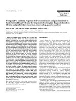
Figure 1 shows the image of a laser-fabricated three-
cantilever array. Each cantilever is 600
m long and
250
m wide. The base area is machined for the purpose of
mounting. A gold film of 50 nm thickness is evaporated on
a)
Electronic mail:
FIG. 1. Image of a three-cantilever array made with the laser microfabrica-
tion technique (cantilever dimension: width 250ϫ length 600ϫ thickness
6
m).
APPLIED PHYSICS LETTERS VOLUME 85, NUMBER 12 20 SEPTEMBER 2004
0003-6951/2004/85(12)/2423/3/$22.00 © 2004 American Institute of Physics2423
Downloaded 05 Oct 2004 to 128.46.190.164. Redistribution subject to AIP license or copyright, see />one side of the cantilever freshly after the laser machining
for DNA immobilization.
The biosensor system we developed in this work in-
cludes a fluid cell inside which the microcantilever is
mounted, a syringe or a syringe pump, an optical beam de-
flection measuring system, and a charge-coupled-device
(CCD) monitoring system, as shown in Fig. 2. The whole
detection system is mounted on an optical table to reduce
vibration. A cubic box made of acrylic is used to cover the
biosensor to prevent disturbance from the air flow and back-
ground light. The base of the sensor system is made of brass
to improve stability. The fluid cell is made of acrylic, which
is inert to chemicals involved in our experiments. The moni-
toring optics is basically a microscope system, which in-
cludes a black/white CCD (SY-VCB3524, SANYO),a10
ϫ objective lens (Olympus, Inc.), and a television monitor.
The optical resolution of the monitoring system is about
5
m, which is sufficient for helping to direct the laser beam
onto the cantilever. The polymer cantilever is mounted in the
chamber using adhesives. A diode laser is focused on the
cantilever and the reflected laser beam is aligned onto a
position-sensitive detector (PSD) for the deflection measure-
ment.
We perform DNA hybridization experiments to demon-
strate applications of the polymer biosensor. The probe DNA
is a thiolated single-strained DNA and is absorbed on the
side of cantilevers coated with gold. It is a 12 base oligo-
nucleotide with the sequence of 5
Ј
-HS-͑CH
2
͒6-
TGC ACT AGA CCT-3
Ј
, abbreviated as HS-ssDNA. The
thiolated modification enables covalent binding to the gold-
coated surface. The complementary DNA used as the target
DNA is an ss-DNA with the sequence of 5
Ј
-
AGG TCT AGT GCA-3
Ј
. A noncomplementary ss-DNA
with the sequence of 5
Ј
-TGC ACT AGA CCT-3
Ј
is used as
a reference. The DNA used in this study is synthesized by
standard phosphoramidite chemistry and is purchased from
Integrated DNA Technologies (Coralville, IA). Cantilever
functionalization is prepared before the DNA hybridization
experiment by inserting the fresh coated cantilevers into a
reservoir which is filled with 10
M solution of HS-ssDNA
in 1.0 M potassium phosphate for around 2 h at room tem-
perature. Functionalized cantilevers are stored in a refrigera-
tor at 4°C. They are equilibrated for several hours in the
liquid cell to reach room temperature before use.
DNA hybridization is performed in a saline sodium cit-
rate hybridization buffer—5ϫ SSC buffer (Calbiochem, La
Jolla, CA) at room temperature. The functionalized cantile-
ver is mounted inside the liquid cell and the target DNA is
injected into the cell using a syringe (by hand injection or by
a syringe pump). Nonspecific binding, pH value, polymer–
liquid reaction, as well as polymer swelling, could induce
signal drift. In order to detect the cantilever deflection caused
by DNA hybridization only, the target DNA is injected after
a stable signal is obtained, which typically takes several
hours. The experiment proceeds as follows. First, the liquid
cell is filled with the 5ϫ SSC buffer. After deflection is sta-
bilized, the target DNA in the 5ϫ SSC buffer solution is then
injected. The PSD signal changes are recorded during the
whole hybridization period using a computer data acquisition
system. Only one of the cantilevers in the cantilever array is
monitored since our current sensing system has only one
light source and one PSD.
The environmental and electronic noises of the sensor
system are found by monitoring reflection from a probe
DNA-coated cantilever mounted in the fluid cell filled with
the 5ϫ SSC buffer. The data show that the noise level of the
cantilever in the fluid cell is about 2 nm. Although the opti-
cal system is able to measure cantilever deflection of less
than 1 nm, the detection limit is set by other factors such as
temperature fluctuation and fluid motion.
Cantilever deflection as a function of time for the target
ss-DNA is shown in Fig. 3. For the experiments shown in
Fig. 3, the injection is done by hand which generally causes
some disturbance (a spike) to the signal, as shown in Fig. 3.
The liquid with a total volume of 0.2 mL is injected within
10 s, causing a fast response in the deflection signal, as
shown in Fig. 3. The final deflection of the cantilever is
122 nm for the DNA concentration of 0.5
M. According to
the calibration, the increased deflection indicates that the
cantilever bends downward, away from the DNA-coated side
(the probe DNA is coated on the gold film on the top of the
cantilever). To confirm that the deflection signals are caused
by DNA hybridization, the buffer containing 0.5
M non-
complimentary ss-DNA is also injected. As shown in Fig. 3,
there is no deflection produced after injection.
In the experiments, it is found to be difficult to detect
target ss-DNA with a concentration lower than 0.1
M when
the total injected volume is 0.2 mL; the cantilever deflection
caused by DNA hybridization is close to the noise level at
lower concentrations. In order to increase the detection reso-
lution, a larger volume of target ss-DNA is injected at a slow
and constant speed using a syringe pump. It is thought that
FIG. 2. Experimental setup of the biosensor including a fluid cell, optical
beam deflection measuring system, and CCD monitoring system.
FIG. 3. Detection of microcantilever deflection induced by DNA hybridiza-
tion (hand injections of 0.5
M noncomplementary ss-DNA and 0.5
M
target ss-DNA, injected volume 0.2 mL).
2424 Appl. Phys. Lett., Vol. 85, No. 12, 20 September 2004 X. R. Zhang and X. Xu
Downloaded 05 Oct 2004 to 128.46.190.164. Redistribution subject to AIP license or copyright, see />more target ss-DNA would bind to the probe DNA if a larger
volume of the target ss-DNA solution is continuously in-
jected. Therefore, deflection can be detected at lower DNA
concentrations. In this work, the volume flow rate of the
syringe pump is set at 4 mL/h, and a total volume of
1.67 mL solution is injected into the fluid cell in 25 min. The
results of DNA hybridization at DNA concentrations of 0.05
and 0.01
M are shown in Fig. 4. The resulting cantilever
deflections are 85 and 18 nm for 0.05 and 0.01
M, respec-
tively. For comparison, the 0.5
M noncomplementary ss-
DNA is also injected. A fluctuation the deflection of about
±5 nm is observed which is caused by the syringe pump, but
the mean deflection remains zero. A larger disturbance is
induced when larger injecting speeds are used.
The experimental procedures are repeated for a number
of target ss-DNA concentrations. The results are summarized
in Fig. 5. Comparing the results obtained from biosensors
made of silicon cantilevers,
5
which reported a lowest concen-
tration of the target ss-DNA of 0.08
M, our biosensor is
able to detect lower concentrations ͑0.01
M͒. We believe it
is possible to further improve the sensitivity of our biosen-
sors. Methods for improving a cantilever’s sensitivity are
implied by Eq. (1). For instance, larger deflection could be
produced by increasing the cantilever length or reducing its
thickness while keeping other parameters the same. The
main challenge for a thinner cantilever is to overcome the
cantilever stability problem because the thinner cantilever is
more liable to the flow disturbance. Another method for re-
ducing the noise is to use a reference cantilever for monitor-
ing the disturbance from the environment such as tempera-
ture fluctuation and flow motion.
5,8
Various techniques for
improving sensitivity are currently under development.
In conclusion, we developed a highly sensitive biosensor
based on polymer microcantilevers which are fabricated us-
ing laser micromachining techniques. In DNA hybridization
experiments, we showed that our biosensor is capable of de-
tecting 12 base oligonucleotide with concentrations as low as
0.01
M, higher than that reported in the literature. There-
fore, polymer cantilevers, combined with the laser fabrica-
tion techniques can be a viable alternative to silicon-based
sensors and surface machining techniques.
Support of this work by the National Science Foundation
is acknowledged.
1
C. Clark, Jr. and C. Lyons, Ann. N.Y. Acad. Sci. 102,29(1962).
2
B. Eggins, Biosensors: An Introduction (Wiley, Chichester, 1996),p.8.
3
R. Raiteri, M. Grattarola, H. J. Butt, and P. Skladal, Sens. Actuators B 79,
115 (2001).
4
H. P. Lang, M. Hegner, E. Meyer, and Ch. Gerber, Nanotechnology 13,29
(2002).
5
J. Fritz, M. K. Baller, H. P. Lang, H. Rothuizen, P. Vettiger, E. Meyer,
H J. Güntherodt, Ch. Gerber, and J. K. Gimzeski, Science 288,316
(2000).
6
G. Wu, H. Ji, K. M. Hansen, T. Thundat, R. H. Datar, R. J. Cote, M.
Hagan, A. K. Chakraborty, and A. Majumdar, Proc. Natl. Acad. Sci.
U.S.A. 98, 1560 (2001).
7
G. Wu, R. H. Datar, K. M. Hansen, T. Thundat, R. J. Cote, and A. Ma-
jumdar, Nat. Biotechnol. 19, 856 (2001).
8
C. A. Savran, T. P. Burg, J. Fritz, and S. R. Manalis, Appl. Phys. Lett. 83,
1659 (2003).
9
C. L. Britton, Jr., R. L. Jones, P. I. Oden, Z. Hu, R. J. Warmack, S. F.
Smith, W. L. Bryan, and J. M. Rochelle, Ultramicroscopy 82,17(2000).
10
F. M. Battiston, J P. Ramseyer, H. P. Lang, M. K. Baller, Ch. Gerber, J. K.
Gimzewski, E. Meyer, and H J. Guntherodt, Sens. Actuators B 77,122
(2001).
11
H. Ji, K. M. Hansen, Z. Hu, and T. Thundat, Sens. Actuators B 72,233
(2001).
12
R. Bashir, J. Z. Hilt, O. Elibol, and N. A. Peppas, Appl. Phys. Lett. 81,
3091 (2002).
13
R. Raiteri, H J. Butt, and M. Grattarola, Electrochim. Acta 46,157
(2000).
14
G. G. Stoney, Proc. R. Soc. London, Ser. A 82, 172 (1909).
15
H. Watanabe and M. Yamamoto, J. Appl. Polym. Sci. 64, 1203 (1997).
16
J. Kim and X. Xu, J. Laser Appl. 15,255(2003).
FIG. 4. Detection of microcantilever, deflection induced by DNA hybridiza-
tion (syringe pump injections of 0.5
M noncomplementary ss-DNA, target
ss-DNA with concentrations of 0.05
M and 0.01
M, injected volume
1.67 mL).
FIG. 5. Detection of microcantilever deflection induced by different target
ss-DNA concentrations.
Appl. Phys. Lett., Vol. 85, No. 12, 20 September 2004 X. R. Zhang and X. Xu 2425
Downloaded 05 Oct 2004 to 128.46.190.164. Redistribution subject to AIP license or copyright, see />