plasmonic effects in near field optical
Bạn đang xem bản rút gọn của tài liệu. Xem và tải ngay bản đầy đủ của tài liệu tại đây (508.02 KB, 7 trang )
DOI: 10.1007/s00340-006-2237-7
Appl. Phys. B 84, 3–9 (2006)
Lasers and Optics
Applied Physics B
e.x. jin
x. xu
✉
Plasmonic effects in near-field optical
transmission enhancement through
a single bowtie-shaped aperture
School of Mechanical Engineering, Purdue University, West Lafayette, IN 47907, USA
Received: 27 December 2005/Revised version: 31 March 2006
Published online: 13 May 2006 • © Springer-Verlag 2006
ABSTRACT In this paper, the enhanced optical transmission
through a special type of aperture of a bowtie shape is in-
vestigated through near-field imaging and finite-difference nu-
merical analysis. Under linear polarizations in two orthogonal
directions, the optical near fields of the bowtie aperture and
comparable square and rectangular apertures made in gold and
chromium thin films are measured and compared. The bowtie
aperture is able to provide a nanometer-sized optical spot when
the incident light is polarized across the bowtie gap and deliv-
ers a considerable amount of light. Localized surface plasmons
are clearly observed in the near-field images for both bowtie and
rectangular apertures in gold, but invisible in chromium. Finite-
difference time-domain calculations reveal that, depending on
the polarization of the incident light, the unique optical prop-
erties of the bowtie aperture are a result of either the optical
waveguide and the coupled surface plasmon polariton modes
existing in the bowtie gap or the coupling between the two open
arms of the bowtie aperture.
PACS 81.07 b; 07.79.Fc; 71.36.+c; 78.66.Bz; 42.79.Gn;
42.79.Vb
1 Introduction
The zero-order transmission spectra through a pe-
riodic array of subwavelength holes in metal films have been
shownto exhibitstrong wavelength and geometry dependence
and multiple transmission maxima [1], which are much larger
than the value of a single hole predicted by the standard aper-
ture theory [2]. This extraordinary optical transmission (EOT)
has attracted intensive investigations in order to understand
the fundamental physics involved. Further experiments have
been conducted to analyze the influence of system parame-
ters (for example, metal surface [3, 4] and hole depth [5]),
as well as the reflectance and absorbance spectra [6]. Simi-
lar observations have also been made in systems working in
other frequency regimes [7–9]. Despite the successful experi-
mental demonstrations, the theoretical exploration of EOT
was not straightforward. EOT was initially attributed to the
surface plasmon polaritons (SPPs) [1, 6, 10–13], in which
✉ Fax: +1-765-4940539, E-mail:
(1) the incident light is coupled to SPP modes through the mo-
mentum match provided by the periodicity of the hole array,
(2) light is coupled through the holes due to the evanescent
tunneling effect [14, 15], (3) SPP modes are excited on the
exit side and scattered into transmitted light, again through
the periodic structure, and (4) the efficient transmission oc-
curs via the resonant excitation of SPPs on either or both
sides of the metal film. In order to explain the transmission
enhancement observed in hole arrays in non-metallic and per-
fect conductor films [16, 17], which do not inherently support
SPPs, the initial SPP model was extended by including the
surface EM modes [18] that can be produced by the corru-
gated non-metallic surfaces or perfect conductors [19].
Fundamentally, the optical transmission through a hole ar-
ray is a process involving multiple diffraction of light from
the periodic structure. Therefore, in principle, a complete de-
scription of the diffracted light can be obtained by solving
Maxwell’s equations if
ε, µ, and the geometry of the periodic
structures are known. A dynamical diffraction model was pro-
posed to describe the diffracted wave field in hole arrays in
terms of Bloch wave modes [20]. It is likely that the inherently
coherent diffraction of the Bloch modes (in which the SPP
mode is an integral part) offers a better chance to explain the
physics underlying the enhanced transmission phenomenon.
However, solving the three-dimensional eigenvalue equations
in terms of the complex optical properties of the metallic pe-
riodic structures is not an easy task. A simplified first-order
diffraction model termed the composite diffracted evanescent
wave (CDEW) model including all non-propagating compo-
nents diffracted by the subwavelength feature (only one of
which matches the SPP mode) was therefore proposed [16]
and is able to successfully explain the transmission anomalies
(both enhancement and suppression) in a simple and intuitive
way. Compared to the SPP model, the CDEW model predicts
both the position and the shape of the transmission peak closer
to the experimental data [16] and the solution of the Maxwell
equations [21]. It also explains the time delay experienced by
the light passing through the hole array [22].
Orders ofmagnitude enhancement in transmission through
hole arrays was initially claimed [1] and subsequently quoted,
but a careful comparison between the transmission of a hole
array and that of an isolated hole in a real metal film re-
veals that the transmission efficiency through the hole array
can be enhanced at most by one order at the transmis-
4 Applied Physics B – Lasers and Optics
sion peaks [16, 23]. The modest transmission enhancement
through periodic arrays of subwavelength holes relative to
isolated holes is mainly due to the intrinsic low transmission
property of single circular apertures operated under the cutoff
condition [24], i.e. the low efficiency of evanescent tunnel-
ing through non-propagating modes. In fact, there has been
increased interest recently to demonstrate the effect of the
aperture shape on the transmission properties [25–28]. The
transmission can be further enhanced (one order higher) by
using a subwavelength aperture in a rectangular shape instead
of a circular one as the fundamental element of the periodic ar-
ray [26]. This additional transmission enhancement is related
to the excitation of localized surface plasmon (LSP) modes in-
duced by the polarization effect [23]. The LSP modes enable
the subwavelength rectangular aperture to act as a propagat-
ing waveguide [28] and increase the transmission efficiency
through each aperture.
More recently, a type of unconventional aperture, a ridge
aperture, has been proposed in the context of achieving both
high optical transmission and subwavelength optical reso-
lution as a single subwavelength aperture structure [29–35].
The ridge aperture, featuring a narrow gap connecting two
open arms, adopts the concept of a ridge waveguide in mi-
crowave engineering [36] while having nanometric dimen-
sions designed for optical wavelengths. As a special type
of ridge aperture, a bowtie aperture has been both numer-
ically [31, 35] and experimentally [37] demonstrated to pro-
vide a confined nanometer-scale light spot withintense optical
intensity, therefore providing enhanced optical transmission
at the length scale far beyond the diffraction limit. How-
ever, the mechanism of transmission enhancement through
bowtie apertures has not been fully understood. In this work,
we investigate the near-field optical transmission properties
of bowtie apertures made in gold and chromium films. In
particular, the optical near fields from the bowtie apertures
and comparable regularly shaped (square and rectangular)
apertures are measured using near-field scanning optical mi-
croscopy (NSOM) with a high resolution aperture probe. The
effects of the polarization of incident light and the light-
induced surface plasmons are investigated. Numerical com-
putations based on the finite-difference method are performed
to explore the detailed mechanism of the optical transmission
enhancement through the bowtie aperture.
2 Sample fabrication and the NSOM setup
Nanofabrication techniques are employed to make
the bowtie apertures and comparable regular apertures in two
metal films, gold and chromium. First, a gold or chromium
film is deposited onto quartz substrates by e-beam evapora-
tion. The thickness of both films is chosen to be
160 nm to
limit the direct light transmission through the films. For the
gold sample, a
4-nm-thick chromium film is evaporated first
on the substrate as an adhesion layer. Second, the apertures
are fabricated into the metal films by focused ion beam (FIB)
milling (FEI Strata DB 235). The bowtie aperture is made in
a 2 by 2 array together with comparable regular apertures for
the purpose of comparison. The apertures are separated by
more than
1 µm both in the x and y directions to limit the in-
teractions among apertures. In the gold sample as shown in
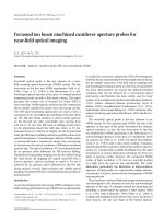
FIGURE 1 SEM images of bowtie apertures and comparable square and
rectangular apertures fabricated in (a) a 160-nm gold film, (b) a 160-nm
chromium film on quartz substrates. The scale bars are 1 µm
the scanning electron microscopy (SEM) image in Fig. 1a, the
bowtie aperture has an outline of about
190 nm by 230 nm and
the gap spacing between the two tips is about
36 nm,whichis
limited by the finite ion-beam size. A small square nanoaper-
ture (upper right in Fig. 1a) of
36 nm by 36 nm is made to
have about the same area as the gap region between the two
tips of the bowtie aperture. The larger square and the rectan-
gular apertures in the lower half of Fig. 1a are about
136 nm
by 136 nm and 450 nm by 50 nm, respectively, approximately
the same opening area as that of the bowtie aperture. In the
chromium sample shown in Fig. 1b, the bowtie aperture has
a
210 nm by 210 nm outline and a 40-nm gap, and the sizes
of the other apertures are
68 nm by 50 nm, 140 nm by 140 nm,
and
500 nm by 50 nm. Much larger rectangular apertures of
a few microns in size are also made in both samples away from
the aperture array for locating the aperture array and aligning
the incident laser beam.
We use NSOM to measure the optical near field transmit-
ted through these apertures. Our NSOM is operated in the
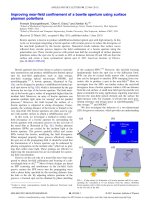
transmission–collection mode. As schematized in Fig. 2, the
aperture sample is illuminated by a linearly polarized helium–
neon laser at
633-nm wavelength from the quartz-substrate
side. The incident laser beam is loosely focused to a spot of
tens of micrometers on the metal film. The transmitted light
through the apertures is collected by a specially fabricated
NSOM probe having a
65 nm by 80 nm silicon nitride core
surrounded with a thin aluminum film. Detailed fabrication
procedures of the NSOM probes will be presented elsewhere.
JIN et al. Plasmonic effects in near-field optical transmission enhancement through a single bowtie-shaped aperture 5
FIGURE 2 Schematic view of near-field scanning optical microscopy
(NSOM) in the illumination–collection mode to measure the optical near
field from the aperture samples
A ×20 objective lens is used to direct the collected photons
into a photomultiplier tube (PMT) placed in the far field. The
same objective lens is also used for imaging purposes. The
probe is first scanned over the sample surface in the constant-
force mode. Although the resolution of the topography image
(not shown here) is in the tens of nanometers range due to the
finite size of the aperture probe, it can still be used to locate the
aperture array. A second scan over the aperture array immedi-
ately follows and the optical signal from the PMT is recorded
by a photon-counting unit to form a NSOM image. The sec-
ond scan is operated in the constant-height mode in order to
limit the topography effect in the NSOM image, and the dis-
tance between the probe and the surface is controlled by the
normal-force feedback based on the cantilever beam deflec-
tion technique, typically in a few nanometers range. For both
samples, the polarization of the illuminating laser is aligned
to be either in the
y direction across the two tips of the bowtie
aperture or in the
x direction while maintaining the same in-
put power in order to determine the polarization dependence
of light transmission through the apertures.
3 Experimental results and discussion
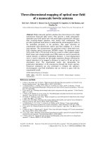
Figure 3a shows a NSOM image obtained from a 2
by 2 aperture array on the gold sample displayed in Fig. 1a,
FIGURE 3 NSOM images of aper-
ture array in the gold sample as
showninFig.1afor(a) y-polarized
and (b) x-polarized light. The arrows
indicate the direction of polarization
with y-polarized laser illumination indicated by the arrow.
The NSOM image is rotated by
45
◦
clockwise with respect
to the corresponding SEM image. With constant-height scan-
ning, the NSOM image can essentially be considered as the
electric field intensity profile at a few nanometers distance
away from the exit plane of the apertures [24]. It can be seen
that three pronounced near-field optical spots are located in
the position of three apertures but there is no discernible op-
tical signal coming out of the smallest square aperture due to
its low transmission compared to other apertures. The peak of
the collected optical signal from the bowtie aperture is com-
parable to that from the rectangular aperture, but significantly
higher than that from the square aperture. The full width at
half magnitude (FWHM) of the optical spots are measured as
98 nm by 75 nm, 103 nm by 134 nm,and186 nm by 86 nm
for the bowtie, square, and rectangular apertures, respectively.
Due to the convolution effect of the finite aperture probe
(
65 nm by 80 nm aperture size), the actual spot size should be
considerably smaller than the measured ones [37]. The trans-
mitted light spot from the bowtie aperture is much smaller
than those from the comparable regular apertures and the
overall size of the bowtie aperture. Considering the symme-
try of the bowtie aperture and the NSOM spot, it is expected
that the light is emitted from the gap of the bowtie aperture. It
therefore confirms that the bowtie aperture is able to provide
enhanced optical transmission at the nanometer scale.
Small signal peaks are found in the vicinity of the ma-
jor optical spots of the bowtie and rectangular apertures and
are distributed along the direction of polarization. These small
peaks are located outside the opening area of both apertures,
indicating that the detected optical emission originates from
the metal surface. As will be discussed later, further near-field
measurements at adifferent laser polarization and on the chro-
mium sample will confirm that the origin of the small peaks is
the LSPs. This direct measurementof theexcitation of LSPs at
near field provides experimental evidence of the role of LSPs
as proposed in explaining the far-field transmission enhance-
ment through a single rectangular aperture [38] or aperture
array [23, 26, 28].
The optical transmission through apertures shows a strong
polarization dependence as evidenced in the NSOM image
in Fig. 3b taken with
x-polarized illumination. First, no op-
tical spot is found in the position of the large rectangular
aperture, showing its low transmission in this polarization.
6 Applied Physics B – Lasers and Optics
Second, the peak signal from the larger square aperture main-
tains the same level as that in Fig. 3a (note that Fig. 3a and
b have different scales), as expected from the symmetry of
the square aperture. Third, the optical spot from the bowtie
aperture is significantly enlarged and featured with two peaks.
Fourth, the magnitude of the peak signal of the bowtie aper-
ture is comparable to the other polarization. Fifth, small signal
peaks are found again in the vicinity of the major peaks of the
bowtie aperture but distributed along the
x direction, i.e. the
direction of laser polarization. The polarization dependence is
a key feature of LSPs, i.e. the LSPs are always excited along
the direction of laser polarization, which further confirms the
excitation of LSPs in shaped apertures.
We treat the square and rectangular apertures in the
160-nm-thick metal films as short optical waveguides in the
z direction [33]. The waveguide cutoff analysis of the optical
waveguide can help us to understand the difference of near-
field light transmission between the square and rectangular
apertures. It is well known that the fundamental (TE mode)
cutoff wavelength for a rectangular waveguide in a perfect
metal is twice the side length of the rectangular cross section
in the direction perpendicular to the transverse electric field.
For the larger square aperture in the array, the cutoff wave-
length is estimated to be about
460 nm considering the red
shift of the cutoff wavelength in real metals [39], i.e. below
the illumination wavelength at
633 nm for both polarizations.
Since there is no propagating mode existing in the wave-
guide when the excitation wavelength is longer than the cutoff
wavelength, an evanescent mode occurs in the square aperture
and the intensity of this mode experiences exponential decay
along the thickness of the metal film, resulting in the attenu-
ated optical signal at the exit side of the aperture as seen in
the NSOM images. On the other hand, the rectangular aper-
ture has two different cutoff wavelengths depending on the
polarization direction of the illuminating laser. It can support
propagating modes when the helium–neon laser is
y polar-
ized or significantly attenuates the
x-polarized light as seen in
Fig. 3.
The enhancement of optical transmission through bowtie
apertures has been previously studied [33, 37]. It was found
that, when illuminated by a
y-polarized light beam, the bowtie
aperture in aluminum is able to support a propagating wave-
guide mode that is localized in the bowtie gap between the
two tips, which not only enhances the optical transmission
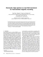
FIGURE 4 NSOM images of aper-
ture array in the chromium sample as
showninFig.1bfor(a) y-polarized
and (b) x-polarized light. The arrows
indicate the direction of polarization
but also provides a nanometer-sized near-field light spot [37].
For the bowtie aperture made in noble metals (silver or gold),
in addition to the propagating waveguide mode, the SPPs ex-
cited along the walls of the bowtie gap also contribute to
the transmission enhancement as will be shown later. The
transmission enhancement for
x-polarized light has not been
reported in the literature. Intuitively, the two open arms of
the bowtie aperture might be treated as cutoff waveguides
considering their subwavelength dimensions. However, these
two triangle-shaped apertures are closely connected by a nar-
row gap, which might introduce a coupling effect in a simi-
lar fashion as the electromagnetic coupling between adjacent
nanoparticles [40] and therefore enhances the transmission
for the
x-polarized illumination. The detailed transmission
mechanism of the bowtie aperture for both polarizations will
be further discussed through finite-difference numerical an-
alysis.
The apertures made in chromium shown in Fig. 1b were
also investigated using NSOM. Figure 4a and b show the
NSOM images for the
y-andx-polarized light illumina-
tions, respectively. For
y-polarized illumination (Fig. 4a), the
bowtie aperture results in the smallest near-field optical spot
with a peak intensity slightly less than that from the rectan-
gular aperture. The bowtie aperture has the highest optical
transmission when the polarization is changed to the
x di-
rection, while no light signal from the rectangular aperture
can be seen in Fig. 4b. A couple of differences between the
chromium and gold samples are worthy of mention. First, the
peak value of the optical spot obtained from the chromium
sample is weaker. Considering the identical illumination con-
ditions, this low light transmission through the chromium film
is mainly due to the smaller skin depth and larger absorption,
which result from the greater absolute value of the imaginary
part of the dielectric constant. The peak intensities from both
the bowtie and rectangular apertures for the
y polarization are
less in chromium than those in gold, and the square aperture
in chromium did not produce transmitted light for both polar-
izations. Second, both the bowtie and rectangular apertures in
chromium produce a clean and single optical near-field spot,
lacking LSP-induced small peaks that are clearly visible in
the gold sample. This confirms the previously observed LSPs
in the gold sample. The excitation of LSPs is associated with
strong local fields as a result of resonant oscillations of free
electrons in noble metals. Noble metals, such as gold and sil-
JIN et al. Plasmonic effects in near-field optical transmission enhancement through a single bowtie-shaped aperture 7
ver, are known to be favorable for SPP/LSP excitations since
their bulk plasma frequencies are in the visible range and the
imaginary part of the dielectric constant has a very small value
at the SPP
/LSP excitation wavelengths [41].
4 Finite-difference numerical analysis
To further illustrate the underlying mechanisms of
the enhanced optical transmission, the finite-difference time-
domain (FDTD) method [42] is used to numerically solve
Maxwell’s equations of light propagation through apertures.
The computational system consists of a quartz substrate layer
(ε =2.25),a160-nm gold or chromium film, and air on each
side. The bowtie apertures with the same dimensions as the
fabricated ones are configured in the middle of the films.
The computational domain of
500 nm×500 nm ×600 nm is
divided into cubic Yee cells [43] of
2nm×2nm×2nm in
size to ensure that the bowtie structure is accurately repre-
sented. The six sides of the computational domain are termi-
nated with the Liao absorbing boundary condition which pro-
vides boundary absorption in the second-order accuracy [44].
The modified Debye model [4] is employed to describe the
frequency-dependent dielectric functions of gold and chro-
mium. The parameters of the Debye model are chosen to
be
σ =1.592 ×10
7
S/m,ε
inf
=10.5,ε
s
=−16889.5,andτ =
9.398 ×10
−15
s to closely fit the experimental data for the real
and imaginary parts of the dielectric constant of gold [45]
in the wavelength range between 550 and
950 nm.Forchro-
mium at
633-nm wavelength [46], the parameters of the De-
bye model are determined to be
σ = 8.62 ×10
5
S/m,ε
inf
=
1.023,ε
s
=−6.92,andτ =8.16×10
17
s.
The incident plane wave at
633-nm wavelength illumi-
nates the bowtie apertures from the quartz substrate side. Both
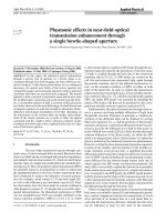
FIGURE 5 Time-averaged (a), (c)
|E
y
|
2
and (b), (d) |E
z
|
2
distributions
of the bowtie aperture in a 160-nm
gold film on quartz substrate com-
puted by the FDTD method. The
y-polarized plane wave at 633-nm
wavelength is incident from the sub-
strate side. (a), (b) show the middle
yz plane across the bowtie gap, and
(c), (d) show the xy plane cutting
through the middle of the gold film
polarizations of incident light used in the NSOM experiments
are calculated. The FDTD results for the gold and chromium
samples under
y-polarized illumination are shown in Figs. 5
and 6, respectively. Figure 5a and b show the time-averaged
|E
y
|
2
and |E
z
|
2
distributions in the middle yz plane across the
bowtie gap, and Fig. 5c and d show these two electric field
components in the
xy plane cutting through the middle of the
gold film. The
E
x
component is orders of magnitude smaller
that the other two components; therefore, it is not displayed.
The
E
y
component shows the character of a TE
10
waveguide
mode from Fig. 5a and c, which is evenly distributed across
the gap. The magnitude of
|E
y
|
2
is enhanced near both the
entrance and exit sides of the aperture, which is associated
with LSP excitation. This feature is also evident in Fig. 5b for
|E
z
|
2
. It should be noted that greater enhanced fields can be
introduced when LSPs are resonantly excited [35]. In Fig. 5b
and d, two SPPs can be distinguished from the distribution of
|E
z
|
2
across the bowtie gap. In fact, this coupled SPP mode
existing in the gap between two metallic walls has been pro-
posed for a new type of waveguide: a metal–dielectric–metal
waveguide [47, 48]. In the bowtie aperture in noble metals,
the combination of the TE
10
waveguide mode and the coupled
SPP mode helps to efficiently deliver the photon energy from
the entrance side to the exit side of the aperture, therefore
enhancing the light transmission together with the excitation
of LSPs induced by the bowtie tips. In addition, both modes
are localized around the nanometer-scale gap between the
two bowtie tips,producing amajor nanometer-sized near-field
light spot as seen in the NSOM measurement(Fig. 3a).The in-
teraction of LSPs with the NSOM probe results in side peaks
with less intensity in the NSOM image. The obtained NSOM
image of the bowtie aperture can therefore be regarded as the
coupling of the near-field probe with the field intensity distri-
8 Applied Physics B – Lasers and Optics
FIGURE 6 Time-averaged (a), (c)
|E
y
|
2
and (b), (d) |E
z
|
2
distributions
of the bowtie aperture in a 160-nm
chromium film on quartz substrate
computed by the FDTD method. The
y-polarized plane wave at 633-nm
wavelength is incident from the sub-
strate side. (a), (b) show the middle
yz plane across the bowtie gap, and
(c), (d) show the xy plane cutting
through the middle of the chromium
film
butions on the exit plane of the aperture, which are similar to
what are shown in Fig. 5c and d. For the bowtie aperture in the
chromium film, the FDTD numerical results show that there is
no SPP mode in the aperture (Fig. 6b and d). The TE
10
wave-
guide mode is dominant in the process of light propagation as
shown in Fig. 6a and c. The
z component of the electric field
at the edges in both the entrance and exit planes of the bowtie
aperture (see Fig. 6b) is caused by the scattering effect [35],
but its intensity is less than the LSP-induced field as compared
with the bowtie aperture in the gold film. As a result, a single
and clean optical spot is found in the NSOM image as shown
in Fig. 4a.
Figure 7 shows the computational results for the bowtie
aperture in the gold film under
x-polarized illumination. Com-
plicated distributions of the electric field are found inside the
aperture, which are no longer confined in the gap area but lo-
cated in the two open arms, therefore resulting in a near-field
spot comparable to the overall area of the bowtie aperture.
FIGURE 7 Time-averaged |E|
2
dis-
tributions of the bowtie aperture
in a 160-nm gold film on quartz
substrate computed by the FDTD
method. The x-polarized plane wave
at 633-nm wavelength is incident
from the substrate side. (a)shows
the middle xz plane cutting through
the middle of the bowtie gap, and
(b)showsthexy plane cutting
through the middle of the gold film
Similar results are seen for the bowtie aperture in the chro-
mium film, which is not displayed here. Therefore, the FDTD
calculations agree with the NSOM measurements in that the
transmitted spots at
x polarization are larger than those at y
polarization. It is possible that the coupling of the two open
arms increases the cutoff property of a single triangular aper-
ture, allowing complicated propagating waveguide modes in
the bowtie aperture.
5 Conclusions
Enhanced optical near-field transmission from
bowtie apertures fabricated in gold and chromium films
was observed via NSOM measurements operated in the
illumination–collection mode. Compared to square and rect-
angular apertures of the same opening area, the bowtie aper-
ture is able to provide a nanometer-sized near-field optical
spot for the incident light polarized across the bowtie gap.
JIN et al. Plasmonic effects in near-field optical transmission enhancement through a single bowtie-shaped aperture 9
The bowtie aperture also delivers a considerable amount of
light when the polarization of the incident light is rotated by
90
◦
. The transmission through the rectangular aperture, on the
other hand, strongly depends on the polarization due to the
high aspect ratio of the two side lengths. LSPs are observed
in the NSOM images for both bowtie and rectangular aper-
tures in gold, but invisible in chromium. The LSP excitation
further enhances the transmission through the apertures but
introduces side peaks around the major optical spot. FDTD
computations reveal that the coupled SPP mode assists the
TE
10
waveguide mode to efficiently deliver the photon en-
ergy from the entrance to the exit of the bowtie aperture in
the gold film when the incident light is polarized across the
bowtie gap, and the coupling of the two open arms enables the
bowtie aperture to act as a propagating waveguide when the
polarization of the incident light is changed to the orthogonal
direction.
ACKNOWLEDGEMENTS The financial support of this work by
the National Science Foundation is gratefully acknowledged. Fabrication of
the aperture samples by FIB machining was carried out in the Center for Mi-
croanalysis of Materials, University of Illinois, which is partially supported
by the US Department of Energy under Grant No. DEFG02-91-ER45439.
REFERENCES
1 T.W. Ebbesen, H.J. Lezec, H.F. Ghaemi, T. Thio, P.A. Wolff, Nature 391,
667 (1998)
2 H. Bethe, Phys. Rev. 66, 163 (1944)
3 D.E. Grupp, H.J. Lezec, T.W. Ebbesen, K.M. Pellerin, T. Thio, Appl.
Phys. Lett. 77, 1569 (2000)
4 T. Thio, H.F. Ghaemi, H.J. Lezec, P.A. Wolff, T.W. Ebbesen, J. Opt. Soc.
Am. B 16, 1743 (1999)
5 A. Degiron, H.J. Lezec, W.L. Barnes, T.W. Ebbesen, Appl. Phys. Lett.
81, 4327 (2002)
6 W.L. Barnes, W.A. Murray, J. Dintinger, E. Devaux, T.W. Ebbesen, Phys.
Rev. Lett. 92, 107 401 (2004)
7 S. Williams, A. Stafford, T. Rogers, S. Bishop, J. Coe, Appl. Phys. Lett.
85, 1472 (2004)
8 J. Rivas, C. Schotsch, P. Bolivar, H. Kurz, Phys. Rev. B 68, 201306
(2003)
9 H. Cao, A. Nahata, Opt. Express 12, 1004 (2004)
10 H. Ghaemi, T. Thio, D. Grupp, T.W. Ebbesen, H. Lezec, Phys. Rev. B 58,
6779 (1998)
11 E. Popov, M. Neviere, S. Enoch, R. Reinisch, Phys. Rev. B 62, 16100
(2000)
12 L. Mart
´
ın-Moreno, F. Garc
´
ıa-Vidal, H. Lezec, K. Pellerin, T. Thio,
J. Pendry, T.W. Ebbesen, Phys. Rev. Lett. 86, 1114 (2001)
13 A. Krishnan, T. Thio, T. Kima, H. Lezec, T. Ebbesen, P. Wolff, J. Pendry,
L. Mart
´
ın-Moreno, F. Garc
´
ıa-Vidal, Opt. Commun. 200, 1 (2001)
14 W. Liu, D. Tsai, Phys. Rev. B 65, 155 423 (2002)
15 S. Darmanyan, A. Zayats, Phys. Rev. B 67, 035 424 (2003)
16 H. Lezec, T. Thio, Opt. Express 12, 3629 (2004)
17 H. Sarrazin, J P. Vigneron, Phys. Rev. E 68, 016603 (2003)
18 L. Mart
´
ın-Moreno, F. Garc
´
ıa-Vidal, Opt. Express 12, 3619 (2004)
19 J.B. Pendry, L. Mart
´
ın-Moreno, F. Garc
´
ıa-Vidal, Sci. Express 10, 1126
(2004)
20 M. Treacy, Phys. Rev. B 66, 195105 (2002)
21 F. Garc
´
ıa-Vidal, H. Lezec, T. Ebbesen, L. Mart
´
ın-Moreno, Phys. Rev.
Lett. 90, 213901 (2003)
22 A. Dogariu, T. Thio, L. Wang, T. Ebbesen, H. Lezec, Opt. Lett. 26, 450
(2001)
23 A. Degiron, T. Ebbesen, J. Opt. A 7
, S90 (2005)
24 S H. Chang, S.K. Gray, G.C. Schatz, Opt. Express 13, 3150 (2005)
25 R. Gordon, A. Brolo, A. McKinnon, A. Rajora, B. Leathem, K. Ka-
vanagh, Phys. Rev. Lett. 92, 037 401 (2004)
26 K.J.K. Koerkamp, S. Enoch, F.B. Segerink, N.F. van Hulst, L. Kuipers,
Phys. Rev. Lett. 92, 183901 (2004)
27 H. Cao, A. Nahata, Opt. Express 12, 3664 (2004)
28 K.L. van der Molen, K.J.K. Koerkamp, S. Enoch, F.B. Segerink, N.F. van
Hulst, L. Kuipers, Phys. Rev. B 72, 045 421 (2005)
29 X. Shi, L. Hesselink, Jpn. J. Appl. Phys. 41, 1632 (2002)
30 K. Tanaka, M. Tanaka, J. Microsc. 210, 294 (2002)
31 K. Sendur, W. Challener, J. Microsc. 210, 279 (2002)
32 A.V. Itagi, D.D. Stancil, J.A. Bain, T.E. Schlesinger, Appl. Phys. Lett.
83, 4474 (2003)
33 E.X. Jin, X. Xu, Jpn. J. Appl. Phys. 1 43, 407 (2004)
34 J. Matteo, D. Fromm, Y. Yuen, P. Schuck, W. Moerner, L. Hesselink,
Appl. Phys. Lett. 85, 648 (2004)
35 E.X. Jin, X. Xu, Appl. Phys. Lett. 86, 111106 (2005)
36 J. Helszajn, Ridge Waveguides and Passive Microwave Components
(IEE, London, 2000)
37 E.X. Jin, X. Xu, Appl. Phys. Lett. 88, 153110 (2006)
38 A. Degiron, H.J. Lezec, N. Yamamoto, T.W. Ebbesen, Opt. Commun.
239, 61 (2004)
39 R. Gordon, A.G. Brolo, Opt. Express 13, 1933 (2005)
40 S.A. Maier, P.G. Kik, H.A. Atwater, Appl. Phys. Lett. 81, 1714 (2002)
41 H. Raether, Surface Plasmons on Smooth and Rough Surfaces and on
Gratings (Springer, Berlin, 1988)
42 K. Kunz, R. Luebbers, The Finite Difference Time Domain Method for
Electromagnetics (CRC, Boca Raton, FL, 1996)
43 S. Yee, IEEE Trans. Antennas Propag. 14, 302 (1966)
44 Z.P. Liao, H.L. Wong, G.P. Yang, Y.F. Yuan, Sci. Sin. 28, 1063 (1984)
45 P.B. Johnson, R.W. Christy, Phys. Rev. B 6, 4370 (1972)
46 D.R. Lide, CRC Handbook of Chemistry and Physics (CRC, Boca Raton,
FL, 1996)
47 K. Tanaka, M. Tanaka, Appl. Phys. Lett. 82, 1158 (2003)
48 B. Wang, G.P. Wang, Appl. Phys. Lett. 85, 3599 (2004)