P4 data path and control
Bạn đang xem bản rút gọn của tài liệu. Xem và tải ngay bản đầy đủ của tài liệu tại đây (3.94 MB, 80 trang )
Part IV
Data Path and Control
Feb. 2007
Computer Architecture, Data Path and Control
Slide 1
About This Presentation
This presentation is intended to support the use of the textbook
Computer Architecture: From Microprocessors to Supercomputers,
Oxford University Press, 2005, ISBN 0-19-515455-X. It is updated
regularly by the author as part of his teaching of the upperdivision course ECE 154, Introduction to Computer Architecture,
at the University of California, Santa Barbara. Instructors can use
these slides freely in classroom teaching and for other
educational purposes. Any other use is strictly prohibited. ©
Behrooz Parhami
Edition
Released
Revised
Revised
Revised
Revised
First
July 2003
July 2004
July 2005
Mar. 2006
Feb. 2007
Feb. 2007
Computer Architecture, Data Path and Control
Slide 2
A Few Words About Where We Are Headed
Performance = 1 / Execution time
simplified to 1 / CPU execution time
CPU execution time = Instructions CPI / (Clock rate)
Performance = Clock rate / ( Instructions CPI )
Try to achieve CPI = 1
with clock that is as
high as that for CPI > 1
designs; is CPI < 1
feasible? (Chap 15-16)
Design memory & I/O
structures to support
ultrahigh-speed CPUs
(chap 17-24)
Feb. 2007
Define an instruction set;
make it simple enough
to require a small number
of cycles and allow high
clock rate, but not so
simple that we need many
instructions, even for very
simple tasks (Chap 5-8)
Computer Architecture, Data Path and Control
Design hardware
for CPI = 1; seek
improvements with
CPI > 1 (Chap 13-14)
Design ALU for
arithmetic & logic
ops (Chap 9-12)
Slide 3
IV Data Path and Control
Design a simple computer (MicroMIPS) to learn about:
• Data path – part of the CPU where data signals flow
• Control unit – guides data signals through data path
• Pipelining – a way of achieving greater performance
Topics in This Part
Chapter 13 Instruction Execution Steps
Chapter 14 Control Unit Synthesis
Chapter 15 Pipelined Data Paths
Chapter 16 Pipeline Performance Limits
Feb. 2007
Computer Architecture, Data Path and Control
Slide 4
13 Instruction Execution Steps
A simple computer executes instructions one at a time
• Fetches an instruction from the loc pointed to by PC
• Interprets and executes the instruction, then repeats
Topics in This Chapter
13.1 A Small Set of Instructions
13.2 The Instruction Execution Unit
13.3 A Single-Cycle Data Path
13.4 Branching and Jumping
13.5 Deriving the Control Signals
13.6 Performance of the Single-Cycle Design
Feb. 2007
Computer Architecture, Data Path and Control
Slide 5
13.1 A Small Set of Instructions
R
I
31
op
25
rs
20
rt
15
rd
10
sh
fn
5
6 bits
5 bits
5 bits
5 bits
5 bits
6 bits
Opcode
Source 1
or base
Source 2
or dest’n
Destination
Unused
Opcode ext
J
jta
imm
Operand / Offset, 16 bits
Jump target address, 26 bits
inst
Instruction, 32 bits
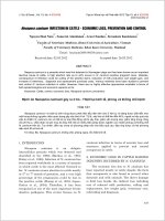
Fig. 13.1
MicroMIPS instruction formats and naming of the various fields.
We will refer to this diagram later
Seven R-format ALU instructions (add, sub, slt, and, or, xor, nor)
Six I-format ALU instructions (lui, addi, slti, andi, ori, xori)
Two I-format memory access instructions (lw, sw)
Three I-format conditional branch instructions (bltz, beq, bne)
Four unconditional jump instructions (j, jr, jal, syscall)
Feb. 2007
Computer Architecture, Data Path and Control
Slide 6
0
The MicroMIPS
Instruction Set
Copy
Arithmetic
Logic
Memory access
Control transfer
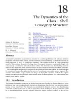
Table 13.1
Feb. 2007
Instruction
Usage
Load upper immediate
Add
Subtract
Set less than
Add immediate
Set less than immediate
AND
OR
XOR
NOR
AND immediate
OR immediate
XOR immediate
Load word
Store word
Jump
Jump register
Branch less than 0
Branch equal
Branch not equal
Jump and link
System call
lui
rt,imm
add
rd,rs,rt
sub
rd,rs,rt
slt
rd,rs,rt
addi rt,rs,imm
slti rd,rs,imm
and
rd,rs,rt
or
rd,rs,rt
xor
rd,rs,rt
nor
rd,rs,rt
andi rt,rs,imm
ori
rt,rs,imm
xori rt,rs,imm
lw
rt,imm(rs)
sw
rt,imm(rs)
j
L
jr
rs
bltz rs,L
beq
rs,rt,L
bne
rs,rt,L
jal
L
syscall
Computer Architecture, Data Path and Control
op fn
15
0
0
0
8
10
0
0
0
0
12
13
14
35
43
2
0
1
4
5
3
0
Slide 7
32
34
42
36
37
38
39
8
12
13.2 The Instruction Execution Unit
beq,bne
syscall
R
31
I
Next addr
bltz,jr
jta
op
25
rs
20
10
sh
fn
5
5 bits
5 bits
5 bits
5 bits
6 bits
Opcode
Source 1
or base
Source 2
or dest’n
Destination
Unused
Opcode ext
J
jta
imm
Operand / Offset, 16 bits
Jump target address, 26 bits
(rs)
12 A/L,
lui,
lw,sw
ALU
22 instructions
Address
Data
Data
cache
(rt)
imm
op fn
Control
Fig. 13.2
Abstract view of the instruction execution unit for MicroMIPS.
For naming of instruction fields, see Fig. 13.1.
Feb. 2007
0
inst
Reg
file
inst
rd
Instruction, 32 bits
rs,rt,rd
Instr
cache
15
6 bits
j,jal
PC
rt
Computer Architecture, Data Path and Control
Slide 8
13.3 A Single-Cycle Data Path
Incr PC
Next addr
jta
Next PC
(PC)
PC
Instr
cache
ALUOvfl
rs
rt
inst
rd
31
0
1
2
op
(rs)
Ovfl
Reg
file
ALU
(rt)
/
16
imm
Instruction fetch
Fig. 13.3
Feb. 2007
ALU
out
Data
addr
Data
cache
Data
out
Data
in
Func
0
32
SE / 1
0
1
2
Register input
fn
RegDst
Br&Jump
Register
writeback
ALUSrc
RegWrite
Reg access / decode
ALUFunc
ALU operation
DataRead
RegInSrc
DataWrite
Data access
Key elements of the single-cycle MicroMIPS data path.
Computer Architecture, Data Path and Control
Slide 9
ConstVar
Shift function
Constant
5
amount
0
Amount
5
1
5
Variable
amount
2
00
01
10
11
No shift
Logical left
Logical right
Arith right
Shifter
Function
class
32
5 LSBs
x
Shifted y
c0
32
Adder
y
32
k
/
c 31
imm
x y
0 or 1
MSB
32
c 32
0
An ALU for
MicroMIPS
lui
00
01
10
11
Shift
Set less
Arithmetic
Logic
2
1
32
2
Shorthand
symbol
for ALU
s
Control
3
x
Func
AddSub
s
ALU
Logic
unit
AND
OR
XOR
NOR
00
01
10
11
y
32input
NOR
Zero
Ovfl
2
Logic function
Zero
Ovfl
Fig. 10.19 A multifunction ALU with 8 control signals (2 for function class,
1 arithmetic, 3 shift, 2 logic) specifying the operation.
Feb. 2007
Computer Architecture, Data Path and Control
Slide 10
13.4 Branching and Jumping
Update
options
for PC
(PC)31:2 + 1
(PC)31:2 + 1 + imm
(PC)31:28 | jta
(rs)31:2
SysCallAddr
Default option
When instruction is branch and condition is met
When instruction is j or jal
When the instruction is jr
Start address of an operating system routine
Lowest 2 bits of
PC always 00
IncrPC
BrTrue
/
30
Adder
/
30
c in
0
1
2
3
NextPC
/
30
PCSrc
Fig. 13.4
Feb. 2007
/
30
/
30
/
30
/
30
4 MSBs 1
/
30
Branch
condition
checker
/
32
30
MSBs
SE
/
30
/
32
/
30
4
16
imm
MSBs
/
26
(rt)
(rs)
(PC)31:2
jta
SysCallAddr
BrType
Next-address logic for MicroMIPS (see top part of Fig. 13.3).
Computer Architecture, Data Path and Control
Slide 11
13.5 Deriving the Control Signals
Table 13.2 Control signals for the single-cycle MicroMIPS implementation.
Control signal
Reg
file
ALU
Data
cache
Next
addr
Feb. 2007
0
1
2
3
RegWrite
Don’t write
Write
RegDst1, RegDst0
rt
rd
$31
RegInSrc1, RegInSrc0
Data out
ALU out
IncrPC
ALUSrc
(rt )
imm
AddSub
Add
Subtract
LogicFn1, LogicFn0
AND
OR
XOR
NOR
FnClass1, FnClass0
lui
Set less
Arithmetic
Logic
DataRead
Don’t read
Read
DataWrite
Don’t write
Write
BrType1, BrType0
No branch
beq
bne
bltz
PCSrc1, PCSrc0
IncrPC
jta
(rs)
SysCallAddr
Computer Architecture, Data Path and Control
Slide 12
Feb. 2007
Computer Architecture, Data Path and Control
0
1
1
0
1
0
0
FnClass
LogicFn
00
01
10
11
00
01
10
00
10
10
01
10
01
11
11
11
11
11
11
11
10
10
0
0
0
0
0
0
0
0
0
0
0
0
0
1
0
0
0
0
0
0
0
0
0
0
0
0
0
0
0
0
0
0
0
0
0
0
1
0
0
0
0
0
0
0
PCSrc
10 10
1
0
0
0
1
1
0
0
0
0
1
1
1
1
1
Add’Sub
01
01
01
01
01
01
01
01
01
01
01
01
01
00
ALUSrc
00
01
01
01
00
00
01
01
01
01
00
00
00
00
BrType
1
1
1
1
1
1
1
1
1
1
1
1
1
1
0
0
0
0
0
0
1
0
DataW rite
001111
000000 100000
000000 100010
000000 101010
001000
001010
000000 100100
000000 100101
000000 100110
000000 100111
001100
001101
001110
100011
101011
000010
000000 001000
000001
000100
000101
000011
000000 001100
DataRead
Load upper immediate
Add
Subtract
Set less than
Add immediate
Set less than immediate
AND
OR
XOR
NOR
AND immediate
OR immediate
XOR immediate
Load word
Store word
Jump
Jump register
Branch on less than 0
Branch on equal
Branch on not equal
Jump and link
System call
fn
RegInSrc
op
RegDst
Table 13.3
Instruction
RegWrite
Control
Signal
Settings
00
00
00
00
00
00
00
00
00
00
00
00
00
00
00
00
00
00
00
00
00
00
00
00
00
00
00
00
00
00
01
10
00
00
00
01
11
11
01
10
00
Slide 13
Control Signals in the Single-Cycle Data Path
Incr PC
Next addr
jta
Next PC
(PC)
PC
Instr
cache
Br&Jump
001111
000000
BrType
Fig. 13.3
Feb. 2007
0
1
2
rd
31
(rs)
Ovfl
Reg
file
ALU
(rt)
/
16
imm
op
00 00
00 00
rs
rt
inst
lui
slt
PCSrc
ALUOvfl
ALU
out
Register input
fn
00
01
RegDst
010101
1
1
RegWrite
1
0
ALUSrc
Data
cache
Data
out
Data
in
Func
0
32
SE / 1
Data
addr
x xx 00
1 xx 01
ALUFunc
0
0
0
0
01
01
DataRead
RegInSrc
DataWrite
AddSub LogicFn FnClass
Key elements of the single-cycle MicroMIPS data path.
Computer Architecture, Data Path and Control
0
1
2
Slide 14
fn
0
RtypeInst
3
4
5
bltzInst
jInst
jalInst
beqInst
bneInst
8
addiInst
1
2
10
sltiInst
12
13
14
15
andiInst
oriInst
xoriInst
luiInst
35
lwInst
43
Feb. 2007
0
8
jrInst
12
syscallInst
32
addInst
34
subInst
36
37
38
39
andInst
orInst
xorInst
norInst
42
sltInst
swInst
63
Fig. 13.5
/6
fn Decoder
1
/6
op Decoder
Instruction
Decoding
op
63
Instruction decoder for MicroMIPS built of two 6-to-64 decoders.
Computer Architecture, Data Path and Control
Slide 15
Control Signal Generation
Auxiliary signals identifying instruction classes
arithInst = addInst subInst sltInst addiInst sltiInst
logicInst = andInst orInst xorInst norInst andiInst oriInst xoriInst
immInst = luiInst addiInst sltiInst andiInst oriInst xoriInst
Example logic expressions for control signals
RegWrite = luiInst arithInst logicInst lwInst jalInst
addInst
subInst
jInst
ALUSrc = immInst lwInst swInst
AddSub = subInst sltInst sltiInst
DataRead = lwInst
PCSrc0 = jInst jalInst syscallInst
Feb. 2007
Computer Architecture, Data Path and Control
.
.
.
Control
.
.
.
sltInst
Slide 16
Putting It All Together
Fig. 13.4
/
30
IncrPC
/
30
/
30
Adder
0
1
2
3
/
30
/
30
/
30
/
30
/
30
/
30
1
4 MSBs
/
32
/
32
/
30
4
16
imm
MSBs
ConstVar
/
26
Cons tant
5
amount
0
Amount
(rs)
Variable
amount
5
1
5
(PC)31:2
jta
2
00
01
10
11
imm
Shifted y
5 LSBs
x
y
BrType
No shift
Logical lef t
Logical right
Arith right
Shifter
0 or 1
c0
32
Adder
SysCallAddr
PCSrc
Shift function
(rt)
32
30
MSBs
SE
c in
NextPC
Branch
condition
checker
BrTrue
Fig. 10.19
32
k
/
c
c 32 31
x y
MSB
32
Function
class
0
00
01
10
11
lui
Shift
Set less
Arithmetic
Logic
2
1
32
2
Shortha
symb
for AL
s
Cont
3
x
Fun
AddSub
A
Incr PC
Next addr
jta
Next PC
(PC)
PC
Instr
cache
rd
31
imm
op
AND
OR
XOR
NOR
ALUOvfl
rs
rt
inst
Logic
unit
Fig. 13.3
0
1
2
00
01
10
11
2
Logic function
(rs)
Ovfl
Reg
file
ALU
(rt)
/
16
0
32
SE / 1
Func
ALU
out
Data
addr
Data
cache
Data
out
Data
in
Zero
Ovfl
addInst
subInst
jInst
0
1
2
Register input
fn
y
32input
NOR
.
.
.
Control
.
.
.
sltInst
Br&Jump
Feb. 2007
RegDst
RegWrite
ALUSrc
ALUFunc
DataRead
RegInSrc
DataWrite
Computer Architecture, Data Path and Control
Slide 17
Zero
O
13.6 Performance of the Single-Cycle Design
An example combinational-logic data path to compute z := (u + v)(w – x) / y
u
v
w
x
y
Feb. 2007
Add/Sub
latency
2 ns
Multiply
latency
6 ns
Divide
latency
15 ns
+
Note that the divider gets its
correct inputs after 9 ns,
but this won’t cause a problem
if we allow enough total time
Total
latency
23 ns
/
z
Beginning with inputs u, v, w, x, and y
stored in registers, the entire computation
can be completed in 25 ns, allowing 1
ns each for register readout and write
Computer Architecture, Data Path and Control
Slide 18
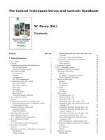
Performance Estimation for Single-Cycle MicroMIPS
Instruction access
2 ns
Register read
1 ns
ALU operation
2 ns
Data cache access
2 ns
Register write
1 ns
Total
8 ns
Single-cycle clock = 125 MHz
R-type 44%
6 ns
Load
24%
8 ns
Store
12%
7 ns
Branch 18%
5 ns
Jump
2%
3 ns
Weighted mean 6.36 ns
ALU-type
P
C
Load
P
C
Store
P
C
Branch
P
C
Jump
P
C
(and jr)
(except
jr & jal)
Not
used
Not
used
Not
used
Not
used
Not
used
Not
used
Not
used
Not
used
Not
used
Fig. 13.6 The MicroMIPS data path unfolded (by depicting the register write
step as a separate block) so as to better visualize the critical-path latencies.
Feb. 2007
Computer Architecture, Data Path and Control
Slide 19
How Good is Our Single-Cycle Design?
Clock rate of 125 MHz not impressive
How does this compare with
current processors on the market?
Not bad, where latency is concerned
Instruction access
2 ns
Register read
1 ns
ALU operation
2 ns
Data cache access
2 ns
Register write
1 ns
Total
8 ns
Single-cycle clock = 125 MHz
A 2.5 GHz processor with 20 or so pipeline stages has a latency of about
0.4 ns/cycle 20 cycles = 8 ns
Throughput, however, is much better for the pipelined processor:
Up to 20 times better with single issue
Perhaps up to 100 times better with multiple issue
Feb. 2007
Computer Architecture, Data Path and Control
Slide 20