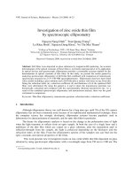
controlled growth of zinc oxide microrods by hydrothermal process
Bạn đang xem bản rút gọn của tài liệu. Xem và tải ngay bản đầy đủ của tài liệu tại đây (1.59 MB, 7 trang )
Controlled growth of zinc oxide microrods by hydrothermal process
on porous ceramic supports for catalytic application
Supamas Danwittayakul
a,b
, Joydeep Dutta
b,c,
⇑
a
National Metal and Materials Technology Center, 114 Thailand Science Park, Paholyothin Rd., Klong Luang, Pathumthani, Thailand
b
Center of Excellence in Nanotechnology, Asian Institute of Technology, P.O. Box 4, Klong Luang, Pathumthani 12120, Thailand
c
Chair in Nanotechnology, Water Research Center, Sultan Qaboos University, P.O. Box 33, 123 Al Khoud, Oman
article info
Article history:
Received 16 July 2013
Received in revised form 1 October 2013
Accepted 3 October 2013
Available online 14 October 2013
Keywords:
ZnO microrods
Hydrothermal process
Porous ceramic substrates
Catalytic application
abstract
The growth of zinc oxide (ZnO) microrods on porous ceramic substrates by mild hydrothermal process
was studied. One-dimensional ZnO microrods were grown on ZnO nanoparticle seeded substrates by
using equimolar concentration of zinc nitrate and hexamethylenetetramine at temperatures lower than
100 °C. We found that the growth of ZnO microrods on alumina and diatomite substrates were affected
due to hydrolysis of substrate surfaces. Stunted ZnO microrod growth on
c
-alumina and diatomite sub-
strates were attributed to arise due to the degradation of hexamine molecules in the growth solution.
Adjusting the pH prior to the growth of ZnO microrods on both alumina and diatomite lead to the growth
of ZnO microrods similar to what is observed on flat glass substrates. Cordierite does not hydrolyze easily
and hence ZnO microrods with aspect ratio as high as 24, were obtained without any pH control of the
growth solution. Copper nanoparticles deposited on ZnO microrods were utilized as a catalyst for meth-
anol steam reforming and about 14% hydrogen yield was obtained with almost 90% methanol conversion
at reforming temperature of 350 °C.
Ó 2013 Elsevier B.V. All rights reserved.
1. Introduction
Porous ceramics are important for many industries where high
surface area, chemical physical and thermally resistant materials
are a requirement [1,2]. Applications of porous ceramics extends
from filtration to use in mechanical seals and as catalyst supports.
Zinc oxide (ZnO) nanostructures have recently attracted consid-
erable attention due to diverse potential applications [3]. ZnO crys-
tals have anisotropic structure with polar and non-polar surfaces
that lead to the possibility of growing nanorod or nanowire struc-
tures [4]. One-dimensional structures like nanorods or nanowires
of ZnO have been used in a wide range of applications from gas
sensors, solar cells, optoelectronics to piezoelectric devices. It is
generally agreed that varying the morphology suits different appli-
cations of ZnO nanomaterials [4]. For gas sensor applications, high
surface area of the sensing parts in devices can improve sensitivity
and allow the possibility to miniaturize devices [5]. While highly
dense ZnO microrods on a substrates are preferred for gas sensor
and solar cell applications [6], ZnO based nanogenerators require
gap between nanorods for bending during the energy harvesting
processes [7–9]. ZnO as a component in catalysts for hydrogen
production through methanol reforming process is also being pur-
sued by several groups including ours [10–14]. Copper–zinc oxide–
alumina (Cu/ZnO/Al
2
O
3
) has been used as a catalyst for methanol
synthesis and it was demonstrated that the use of catalyst support
enhanced catalytic stability due to its ability to withstand higher
temperatures [14,15].
Several techniques have been utilized to synthesize ZnO nano-
rod arrays such as chemical vapor deposition, sol–gel and hydro-
thermal processes, etc. Chemical vapor deposition is an
expensive technique while sol–gel and hydrothermal processes
are relatively straight-forward as they do not require any compli-
cated systems during synthesis. Hydrothermal process is a simple
and low temperature technique for the growth of zinc oxide single
crystals [16]. Vayssieres et al. first proposed the low temperature
epitaxial growth of ZnO microrods on various substrates from
equimolar concentrations of zinc nitrate ((Zn(NO
3
)
2
) and hexa-
methylenetetramine (hexamine, C
6
H
12
N
4
) precursors [17]. Since
this early work, ZnO microrods were successfully grown on flat
substrates such as glass [4], transparent conducting oxide film
[18], stainless steel [14], paper and flexible polymeric fibers
[19,20], amongst others. Though many groups have worked on
ZnO microrod growth on solid substrates, there still is a gap in
the understanding of hydrothermal growth of ZnO microrods on
porous ceramic substrates.
In this study, we compare the growth of ZnO microrods on
popular ceramic substrates specifically, alumina, calcined
0925-8388/$ - see front matter Ó 2013 Elsevier B.V. All rights reserved.
/>⇑
Corresponding author at: Chair in Nanotechnology, Water Research Center,
Sultan Qaboos University, P.O. Box 33, 123 Al Khoud, Oman. Tel.: +968 24143266;
fax: +968 24413532.
E-mail address: (J. Dutta).
Journal of Alloys and Compounds 586 (2014) 169–175
Contents lists available at ScienceDirect
Journal of Alloys and Compounds
journal homepage: www.elsevier.com/locate/jalcom
diatomite and cordierite with an aim to understand and control the
growth of ZnO microrods by hydrothermal process on porous sub-
strates. The ZnO microrods on ceramic supports were utilized as a
catalyst support for methanol steam reformation (MSR). Different
catalysts have been used for methanol steam reforming amongst
which copper (Cu) on ZnO supports show very high catalytic activ-
ity and hydrogen selectivity [21]. In this work, copper nanoparti-
cles were deposited on ZnO microrods (Cu–ZnO MR) by
conventional impregnation technique. Prepared Cu–ZnO MR cata-
lysts were then utilized for examining the catalytic activities on
MSR using a packed tubular reactor operating at temperatures up
to 350 °C.
2. Experimental
ZnO microrods were grown using a modified method suggested by Guo et al. [4]
that compose of ZnO seeding on a substrate followed by a hydrothermal growth
process for the microrod growth [4]. Seeding the substrates lead to the formation
of ZnO microrods in a preferential direction [22]. Prior to seeding and growth pro-
cesses, all ceramic and reference glass substrates were prepared and cleaned to re-
move any surface contaminants.
The glass slides were immersed in detergent solution, sonicated for 20 min and
then thoroughly washed with deionized water. The glass slides were then dried in
an atmospheric oven at 95 °C overnight. Three types of ceramic substrates namely
alumina, calcined diatomite and cordierite which were selected to study the growth
of ZnO microrods on porous substrates, and were prepared from commercially
available materials (Table 1) that were uniaxially pressed using a hydraulic press
to form 1–2 mm thick pellets of 20 mm diameter. All pellets were then calcined
at 1000 °C for 2 h in the ambient for strengthening, prior to further use. All pellets
were then cleaned by sonication in deionized water for 5 min and dried in a furnace
at 200 °C for 1 h in air. Substrate densities were examined by following ASTM C20
(2010) protocal [23]. Specific surface areas (S.S.A.) of substrates were determined
using gas adsorption technique (Autosorb-1C; Quantachrome Ins.) where 0.5 g of
each sample was outgassed at 300 °C for 5 h prior to the 5-point BET measure-
ments. X-ray diffraction analysis (XRD; PANalytical, X’Pert PRO) was carried out
to study the crystal structure of the modified ceramic substrates.
2.1. Zinc oxide seeding process
All chemicals used for ZnO nanoparticle synthesis were of analytical grade. Zinc
acetate dihydrate (Zn(CH
3
COO)
2
2H
2
O) and sodium hydroxide obtained from Merck
were used as a zinc and hydroxyl precursors to synthesize ZnO nanoparticles. 4 mM
zinc acetate solution was gradually mixed with 4 mM sodium hydroxide in ethanol
(Merck) and then the Zn
2+
sol was allowed to hydrolyze under controlled aging in
air at 60 °C for 3 h. Hydrolyzed Zn
2+
sol initially formed Zn(OH)
2
gel that turns into
ZnO colloids upon aging. Seeding the substrates were then conducted by dipping
ceramic substrates into ZnO colloids for 15 min and then dried in an oven for
15 min; this process was repeated thrice. The seeded substrates were then annealed
at 350 °C for 5 h in air and stored in a dehumidified chamber for further use.
2.2. Hydrothermal growth of zinc oxide microrods
Zinc nitrate hexahydrate (Zn(NO
3
)
2
6H
2
O) purchased from Merck was used as a
zinc precursor during the ZnO microrod growth. The seeded substrates were in-
serted in an equimolar solution of zinc nitrate and hexamine heated to 95 °C for
up to 10 h. In a sealed chemical bath, equimolar (5–10 mM) solution of zinc nitrate
and hexamine was replenished every 5 h to ascertain the ready availability of zinc
ions in the growth solution [24]. The substrates after ZnO growth were finally an-
nealed at 350 °C for 1 h in the ambient prior to further use. Each specimen was
investigated using field emission scanning electron microscope (FESEM,
JEOL-6301) working at 20 kV to record the morphology of microrods. Shape and
sizes of ZnO microrods were determined from the micrographs by using standard
image analysis software (ImageJ software).
2.3. A catalyst support application of ZnO microrods on cordierite subtrates
2.3.1. Preparation copper/zinc oxide microrod catalysts (Cu–ZnO MR)
Copper nanoparticles used in this work have been prepared as a colloidal dis-
persion by heterogeneous precipitation. The synthesis was carried out in an aque-
ous solution under constant stirring using 0.46 mM copper nitrate as a copper
precursor and hydrazine as a reducing agent [25,26]. Polyvinylpyrolidone (PVP)
5 wt% in deionized water was added for stabilization of the colloids. Copper nano-
particles were deposited on ZnO microrods grown on the substrates by impregna-
tion technique. The ZnO microrod supports were immersed in the copper colloidal
suspensions at 95 °C for 2 h. Excess copper nanoparticles which did not attach to
the microrods were then removed by rinsing the samples with deionized water.
The immersed samples were finally calcined at 300 °C for 1 h in air. Each specimen
was investigated using field emission scanning electron microscope (FESEM, JEOL-
6301) working at 20 kV to record the morphology of copper nanoparticles on ZnO
microrods. Copper and zinc contents were determined using inductively coupled
plasma-optical emission spectrometer (ICP-OES: Horiba, Activa). First, the catalyst
samples were weighed and heated at 95 °C and then soaked in strong sulfuric acid
for 3 h to allow metals and metal oxides to be released from the substrates. Zinc
oxide, copper and copper (I) oxide are readily dissolved in sulfuric acid while copper
(II) oxide forms copper sulfate before dissolving in water. Adjusted final volume of
released metal ions in the solution were used to determine the contents of copper
and zinc using ICP-OES.
2.3.2. Steam reforming of methanol
The steam reforming of methanol were carried out at atmospheric pressure in a
packed electrically heated tubular reactor of 20 mm diameter in a 20 cm long
heated zone schematically represented in Fig. 1. Methanol steam reforming was
performed at varying temperatures ranging from 200 °C to 350 °C in the presence
of 0.5 g of as-prepared catalysts that were ground and packed in the reactor. Prior
to methanol steam reforming process, catalyst were activated by flowing 60 mL/
min of 5% H
2
in argon at 300 °C for 1 h. Water to methanol ratio of 0.8 mol was used
for all the reforming experiments. An ultrasonic transducer was used to generate
aerosols of the reactant which was then carried into the reaction zone by flowing
20 mL/min of argon gas through the aerosol generator chamber. Gas products were
collected and analyzed by a gas chromatograph (GC, Buck Scientific) connected to a
thermal conductivity detector (TCD). Packed columns of Hyesep D (polyvinylben-
zene, PVB) and molecular sieve 13x were used to separate the gas mixtures.
Table 1
Properties of the ceramic substrates used in this work.
Substrates Source Specific surface
area (m
2
/g)
Substrate density
(g/cm
3
)
Alumina
(
c
-Al
2
O
3
)
Merck 11.21 0.76
Calcined
diatomite
China 9.11 1.58
Cordierite Zhongtian,
Jiangxi, China
14.41 1.70
Fig. 1. Schematically experimental set up for methanol steam reforming system.
170 S. Danwittayakul, J. Dutta /Journal of Alloys and Compounds 586 (2014) 169–175
3. Results and discussion
3.1. ZnO microrod microstructures
Hydrothermal growth of ZnO micro and nanostructures depend
on several synthesis parameters like pH, temperature of hydrolysis,
precursor concentration, etc. [24]. Essentially the concentration of
zinc ions and the availability of hydroxyl groups in the growth
solution balance the consumption or removal of these ions until
it finds an energetically favorable position leading to the epitaxial
growth of the ZnO microrods [17,27].
Growth of ZnO microrods on the three ceramic substrates were
found to be different with exactly similar precursor solution and
growth conditions possibly arising from the ionization reactions
that take place on surfaces of porous ceramic substrates leading
to a change in pH of the growth solution. Strength of ionization
reactions depend on the pH and temperature of reaction [28–30].
It has already been reported that during initial stages of ZnO
growth on glass substrates, growth solution changes from being
slightly acidic to mildly basic, within about one hour of the onset
of the hydrothermal process [24,31]. The growth solution turns ba-
sic during growth process because of hydrolysis reaction as shown
in Eq. (1). Baruah et al. reported that the growth rate of ZnO micro-
rod was maximum in basic conditions during hydrothermal syn-
thesis [23] as hydroxyl ions dominate the reaction process and
the hydrolysis reaction shifts backward following the Le Châtelier’s
principle, resulting in a higher growth rate.
ZnO þ H
2
O $ Zn
2þ
þ 2OH
$ ZnðOHÞ
2
ð1Þ
In order to attain ZnO microrod growth by hydrothermal pro-
cess on ceramic substrates similar to what is achieved on glass sub-
strates, an experiment was designed to monitor the surface state of
these substrates upon continuous exposure to water [4,18].In
Fig. 2, we have plotted the changes in pH of deionized water upon
continued soaking of the porous substrates in 25 mL deionized
water. We found that water in the presence of alumina and diato-
mite substrates showed rapidly increasing pH during first immer-
sion period (30 min) while cordierite and glass substrates did not
influence any substantial changes in the pH over 150 min of
soaking.
The specific surface area and densities of the three ceramic sub-
strates used in this work are summarized in Table 1.
c
-Al
2
O
3
and
diatomite showed almost comparable specific surface areas
(10 m
2
/g) but diatomite was twice as dense as the
c
-Al
2
O
3
sub-
strates (Table 1). Alumina also has larger terminated surfaces than
calcined diatomite and cordierite [32–34]. Cordierite has a higher
specific surface areas (14 m
2
/g) and also higher monolith density
(1.7 g/cm
3
). It is well known that alumina hydrolyzes readily in
contact with water forming hydroxides and forms complexes such
as Al(OH)
2+
,AlðOHÞ
þ
2
, Al(OH)
3
and AlðOHÞ
4
that can raise the pH to-
wards the basic region [29,30,35].
X-ray diffraction (XRD) shows that the cordierite samples
matched with JCPDS No. 09-0472 showing (Mg,Fe)
2
Al
4
Si
5
O
18
while
quartz (JCPDS No. 82-1403), muscovite (JCPDF No. 21-0993) and
anorthite (89-1460) were found in calcined diatomite. Corundum
(calcined alumina, Al
2
O
3
) structure was confirmed for the alumina
substrates (JCPDS No. 76-0144). These results are shown in Fig. 3.
As mentioned before, ZnO microrods grow faster in the basic re-
gion, and hence the growth rate of ZnO microrods on alumina and
diatomite substrates should be faster than on cordierite and glass
substrates [24]. Scanning electron micrograph (SEM) of ZnO micro-
rods shows the homogeneous growth on glass substrate with an
average rod thickness of 170 nm (Fig. 4). The uniformity of the
ZnO microrods on glass substrate is evident with the formation
of microrods 3
l
m in length and 170 nm in diameter. Aspect ra-
tio of ZnO microrods grown on cordierite substrates estimated
from the ratio of length over width was found to be 24. Morphol-
ogy of ZnO microrods grown on cordierite substrate were similar to
Fig. 2. Change in pH of deionized water upon continued soaking of the porous
substrates in 25 mL deionized water.
Fig. 3. XRD patterns of all substrates used in this work, namely, alumina, cordierite and diatomite.
S. Danwittayakul, J. Dutta /Journal of Alloys and Compounds 586 (2014) 169–175
171
the ones observed on glass substrates (Fig. 5). The morphology
could however be controlled by varying Zn
2+
concentration in the
starting precursor solution. In contrast, morphology of ZnO rods
grown on alumina and diatomite substrates exhibited very large
diameter of the microrods as shown in Figs. 6 and 7 which are visu-
ally noticeable in the case of microrods growth with 10 mM Zn
2+
.
For lower concentration of Zn
2+
(5 mM) in the starting solution,
no clear evidence of ZnO microrod growth could be observed on
c
-alumina (Fig. 6a). At slightly higher precursor concentrations
(7–10 mM), microrods with lower aspect ratios are formed as
shown in Fig. 6b and c. Table 2 summarizes length, diameter and
aspect ratios of ZnO microrods grown on different substrates
(Figs. 4–7). As can be observed in Fig. 6b and c and Fig. 7a–c,
ZnO microrod growth was stunted on alumina or diatomite sub-
strates and no growth perpendicular to the substrate were
observed as it is seen for ZnO microrod growth on glass substrates
(Fig. 4). Baruah and Dutta [24] reported that the growth rate of ZnO
microrods were highest in both lateral ½10
10 and longitudinal
[0001] directions in basic conditions and that ZnO nanorods are
known to get eroded in acidic conditions with the final growth
depending upon the competition between growth and dissolution
processes. This explains why thicker ZnO microrods grow on alu-
mina substrates. Similar justification holds true for the ZnO micro-
rod growth on diatomite substrates since it consists of comparable
hygroscopic materials as alumina, leading to a similar change in pH
to basic region, albeit not as strong as in the case of growth on alu-
mina substrates.
In order to grow ZnO microrods with high aspect ratio (ratio of
length to width of the microrods) similar to what we obtained on
glass and cordierite substrates, several experiments of ZnO micro-
rod growth were performed under controlled pH conditions. ZnO
seeded on
c
-alumina and diatomite substrates were immersed in
equimolar concentrations of zinc nitrate and hexamine (10 mM)
and pH of the growth solutions were then adjusted to about 6.4
by gradually adding 1% HNO
3
and then the other growth procedure
were followed as reported. Dense ZnO microrods with high aspect
ratio (20) were successfully grown on both alumina and diato-
mite substrates (Fig. 8) confirming that surface ionization strongly
affects the growth of ZnO microrods on porous substrates.
The observed larger diameter of ZnO microrods grown on alu-
mina and diatomite substrates as compared to the microrods
grown on glass substrates can be attributed to arise due to the con-
tribution of hexamine for the growth of anisotropic ZnO microrods.
The initial growth solution at the substrate interface is slightly
acidic about pH 5.8–6.2 which probably leads to decomposition
of hexamine into ammonia and formaldehyde [4,36]. Hexamine
is well known to degrade in not only acidic conditions but also at
elevated temperatures [36]. Tada [37] reported that in acidic aque-
ous solutions, protonated hexamine ((CH
2
)
6
N
4
H
+
) decomposes to
protonated ammonia raising pH of the solutions which can thus
subsequently lead to accelerated growth of ZnO microrods. Baruah
and Dutta [4] reported that thermal degradation releases the hy-
droxyl ions and first forms Zn(OH)
2
that finally transforms to
ZnO. Hexamine is a chelating agent that attaches to ZnO microrods
securing ZnO non polar facets (10
10) from the deposition of Zn
2+
,
therefore degradation of hexamine lead to a lack of complete cov-
erage on these facets hindering the Zn
2+
attachment. This leads to a
growth in both lateral and longitudinal directions in the ZnO
microrods on alumina and diatomite substrates. Moreover, as ob-
served in earlier section, alumina and diatomite hydrolysis raises
pH of growth solution to basic regions that can promote ZnO
growth [24].
3.2. Copper nanoparticle deposition on zinc oxide microrods (Cu/ZnO
MR)
Uniform copper nanoparticles of 20 nm size were obtained after
stirring the precursor for 30 min at room temperature (Fig. 9a). Cu
colloidal suspension was yellowish-brown in color with the optical
absorption peak at about 570 nm. Spherical copper nanoparticles
of about 50 nm in sizes are firmly attached on ZnO microrods as
shown in Fig. 9b. There are two major causes of an increase in cop-
per nanoparticle size from 20 nm to 50 nm. Firstly, 20 nm sized
particles formed the copper colloids but during the deposition pro-
cess, copper colloid suspension was heated at 95 °C for 2 h in
which ZnO nanorods samples were immersed, as reported in the
literature [38,39]. Upon prolonged heating (for 2 h) at 95 °C,
agglomeration of copper nanoparticles occurred leading to a parti-
cle size of 50 nm. Secondly, the synthesized samples (Cu/ZnO
microrods) were annealed at 300 °C for 1 h which increases the
size of the nanoparticles. The contents of copper and zinc on the
Cu nanoparticle modified ZnO microrods determined using ICP-
OES are summarized in Table 3. The results show that copper
and zinc contents are about 1.3% and 3.7% by weight while Cu/Zn
weight ratio is about 2.8. The copper nanoparticles are mixed
Fig. 4. ZnO microrods grown on glass substrate by hydrothermal process with
20 mM Zn
2+
after 20 h of growth. The precursor solution (equimolar concentration
of Zn(NO
3
)
2
and hexamine) was changed every 5 h during the growth process.
Fig. 5. Morphology of ZnO microrods grown on cordierite substrates by hydrothermal process after 10 h of growth. The precursor solution (equimolar concentration of
Zn(NO
3
)
2
and hexamine) was changed every 5 h during the growth process; (a) 5 mM of Zn
2+
, (b) 10 mM of Zn
2+
and (c) 20 mM of Zn
2+
.
172 S. Danwittayakul, J. Dutta / Journal of Alloys and Compounds 586 (2014) 169–175
phases of copper in the as-prepared catalysts (copper metal form,
copper (I) oxide and copper (II) oxide). However, prior to the refor-
mation process, the catalyst were reduced by flowing 5% hydrogen
in argon gas at 300 °C for 1 h to convert all phases into copper
metal phase. During the reformation process, hydrogen gas pro-
duced from the reforming reaction also adds as a self-reducing
agent for the catalyst system.
3.3. Catalytic activities on MSR
Fig. 10 shows the methanol reforming results using Cu nanopar-
ticles on ZnO microrods (Cu–ZnO MR) grown on cordierite sub-
strate. It was found that the prepared Cu–ZnO MR catalyst
exhibited high methanol conversion (about 90%) even at a low
operating temperature of 200 °C, but low hydrogen yield was ob-
served under these conditions (4% at 200 °C). At elevated temper-
atures, higher hydrogen yields could be obtained (14% hydrogen
yield at 350 °C working temperature). As the hydrogen yields were
lower than the estimated levels, this can be attributed to the for-
mation of intermediate compounds like methoxy (CH
3
O), formal-
dehyde (CH
2
O), methylformate (CH
3
COOH) and formate (HCOOH)
species which could not be further dehydrogenated to produce
hydrogen gas [40–42]. The active site O
(ads)
in Eqs. (2)–(6) can be
a surface Cu–O–Cu group, with Cu in the oxidation state +1 (Cu(II)
is inactive for MSR) [43–46]. Methanol can then react at this site
leading to adsorbed methoxy and OH species (Eq. (2)) followed
Fig. 6. Morphology of ZnO rods grown on
c
-Al
2
O
3
substrates by hydrothermal process after 10 h of growth. The precursor solution (equimolar concentration of Zn(NO
3
)
2
and
hexamine) was changed every 5 h during the growth process; (a) 5 mM of Zn
2+
, (b) 7 mM of Zn
2+
and (c) 10 mM of Zn
2+
; insets of (a) and (c) is the high magnification of top
view ZnO microrod.
Fig. 7. Morphology of ZnO rods grown on calcined diatomite substrates by hydrothermal process after 10 h of growth. The precursor solution (equimolar concentration of
Zn(NO
3
)
2
and hexamine) was changed every 5 h during the growth process; (a) 5 mM of Zn
2+
, (b) 7 mM of Zn
2+
and (c) 10 mM of Zn
2+
.
Table 2
Summary of width, length and aspect ratio of zinc oxide rods grown on glass,
cordierite, alumina and calcined diatomite.
Zn
2+
conc.
(mM)
Glass Cordierite Alumina Calcined
Diatomite
Length (m) 5 1.19 2.38 0 4.84
7 – – 3.86 5.66
10 2.07 2.68 4.05 6.48
20 3.04 3.40 – –
Width (m) 5 0.10 0.11 0 1.73
7 – – 0.79 2.87
10 0.10 0.11 1.03 1.29
20 0.17 0.26 – –
Aspect ratio 5 24.48 22.42 0 2.80
7 – – 4.90 1.97
10 23.75 23.64 3.95 5.04
20 24.01 12.95 – –
Fig. 8. Morphology of ZnO rods grown on
c
-alumina and calcined diatomite substrates by hydrothermal process after 10 h of growth. Prior to the growth process, pH of
growth solution after immersing the substrate was adjusted to about 6.4. The precursor solution (10 mM of equimolar concentration of Zn(NO
3
)
2
and hexamine) was changed
every 5 h during the growth process; (a) on
c
-alumina substrate, (b) calcined diatomite substrate.
S. Danwittayakul, J. Dutta / Journal of Alloys and Compounds 586 (2014) 169–175
173
by the dehydrogenation of the methoxy species, giving rise to ad-
sorbed formaldehyde with simultaneous reduction at the Cu site
(Eq. (3)). Desorption of formaldehyde from the copper surface
can occur upon the oxidation of formaldehyde into formate species
possibly through an intermediate dioxymethylene group (Eqs. (4)
and (5)) [43,47]. During ideal SRM conditions, formate would
decompose to CO
2
(Eq. (6)) instead of forming CO [48–50]. Cu(I)
sites react with H
2
O (Eqs. (8) and (9), where H(ads) is a H atom
bound to a Cu metal site) and is reactivated. Thus Cu undergoes
an oxidation–reduction cycle, catalyzing the abstraction of hydro-
gen atoms from the adsorbed species with subsequent recombina-
tion to form gaseous H
2
(Eq. (10)). The determining step in this
mechanism is the dehydrogenation of adsorbed methoxy groups
[51,52]. For this catalyst carbon dioxide evolution is more prefer-
ential than carbon monoxide and hence it is suitable for fuel cell
applications.
CH
3
OH
ðgÞ
þ O
ðadsÞ
! CH
3
O
ðadsÞ
þ OH
ðadsÞ
ð2Þ
CH
3
O
ðadsÞ
þ OH
ðadsÞ
! CH
2
O
ðadsÞ
þ H
2
O
ðadsÞ
ð3Þ
CH
2
O
ðadsÞ
þ O
ðadsÞ
! CH
2
O
ðadsÞ
ð4Þ
CH
2
O
2ðadsÞ
þ O
ðadsÞ
! HCOO
ðadsÞ
þ OH
ðadsÞ
ð5Þ
HCOO
ðadsÞ
þ O
ðadsÞ
! CO
2ðadsÞ
þ OH
ðadsÞ
ð6Þ
H
2
O
ðgÞ
! H
2
O
ðadsÞ
ð7Þ
OH
ðadsÞ
! O
ðadsÞ
þ H
ðadsÞ
ð8Þ
H
2
O
ðadsÞ
! H
ðadsÞ
þ OH
ðadsÞ
ð9Þ
2H
ðadsÞ
! H
2ðgÞ
ð10Þ
4. Conclusions
We have successfully grown ZnO microrods on porous ceramic
substrates showing morphology similar to what is achieved on flat
glass substrates by a hydrothermal process. ZnO microrods grow
faster on alumina and diatomite substrates compared to cordierite
and glass substrates which was attributed to arise from the surface
basicity of the alumina substrates due to its hydrolysis in the pres-
ence of water. Large ZnO microrods were found on alumina and
diatomite substrates upon hydrothermal growth which were ar-
gued to occur due to the degradation of hexamine into ammonia
and formaldehyde effectively exposing the non-polar facets of
the ZnO crystals and thus adding to the homogeneous growth in
all directions. Surface hydrolysis of alumina and diatomite sub-
strates could be circumvented controlling the pH of the growth
solution during hydrolysis. Cordierite which is not hygroscopic
was found to be an appropriate porous ceramic substrate for the
hydrothermal growth of ZnO microrods with high aspect ratio,
similar to what is achieved on flat glass substrates. Proper under-
standing of ZnO microrod growth on porous substrates allows its
applications as catalytic support for methanol steam reformation
as the deposition of Cu–ZnO microrod on cordierite substrates
could be utilized to reform methanol resulting in 90% conversion
with 14% hydrogen yield at 350 °C.
Acknowledgements
The authors would like to acknowledge partial financial support
from the Center of Excellence in Nanotechnology at the Asian Insti-
tute of Technology, National Nanotechnology Center (NANOTEC)
and National Metal and Materials Technology Center (MTEC),
belonging to the National Science & Technology Development
Agency (NSTDA), Thailand. The authors would also like to acknowl-
edge the support of the Research Council of Oman for partial
support.
Fig. 9. Scanning electron micrographs; (a) copper nanoparticles prepared by using hydrazine as a reducing agent, and (b) copper nanoparticles decorated ZnO nanorods
prepared by a typical impregnation process at 95 °C for 2 h.
Table 3
Copper and zinc contents in the catalyst samples determined by ICP-OES.
Replicate Concentration (wt%)
Cu Zn
1 1.245 3.783
2 1.357 3.562
3 1.282 3.628
Average 1.295 ± 0.057 3.658 ± 0.113
Fig. 10. Catalytic activities on methanol steam reforming using Cu (nps)/ZnO
nanorods grown on cordierite ceramic. The catalysts were activated by flowing
5%H
2
gas (60 mL/min) at 300 °C for 1 h before determination; (a) % methanol
conversion, (b) % hydrogen selectivity, (c) % carbon dioxide selectivity and (d) %
carbon monoxide selectivity.
174 S. Danwittayakul, J. Dutta / Journal of Alloys and Compounds 586 (2014) 169–175
Appendix A. Supplementary material
Supplementary data associated with this article can be found, in
the online version, at />019.
References
[1] R.R. Dessaia, J.A.E. Desaa, D. Senb, S. Mazumderb, J. Alloys Comp. 564 (2013)
125–129
.
[2] T.D. Senguttuvan, Mater. Chem. Phys. 67 (2001) 146–150.
[3] C. Falconi, G. Mantini, A.D. Amico, Z.L. Wang, Sensors Actuator B 139 (2009)
511–519
.
[4] S. Baruah, J. Dutta, Sci. Technol. Adv. Mater. 10 (2009) 013001.
[5] Z. Jing, J. Wang, F. Li, L. Tan, Y. Fu, Q. Li, J. Nanoeng. Nanomanuf. 2 (2012) 133–
142
.
[6] J.J. Hassan, M.A. Mahdi, C.W. Chin, H.A. Hassan, Z. Hassan, J. Alloys Comp. 546
(2013) 107–111
.
[7] Z.L. Wang, Mater. Sci. Eng. Report 64 (2009) 33–71.
[8] R.C. Singh, O. Singh, M.P. Singh, P.S. Chandi, Sensor Actuator B 135 (2008) 352–
357
.
[9] J. Chung, J. Lee, S. Lim, Phys. B Condens. Matter 405 (2010) 2593–2598.
[10] S. Liu, K. Takahashi, K. Fuchigami, K. Uematsu, Appl. Catal. A 299 (2006) 58–65.
[11] Y. Matsumura, H. Ishibe, J. Catal. 268 (2009) 282–289.
[12] Y. Matsumura, H. Ishibe, Appl. Catal. B 91 (2009) 524–532.
[13] S. Danwittayakul, J. Dutta, Chem. Eng. J. 223 (2013) 304–308.
[14] Y.G. Lin, Y.K. Hsu, S.Y. Chen, Y.K. Lin, L.C. Chen, K.H. Chen, Angew. Chem. Int.
Edit. 48 (2009) 7586–7590
.
[15] Z. Wang, W. Wang, G. Lu, Int. J. Hydrogen Energy 28 (2003) 151–158.
[16] S H. Hu, Y C. Chen, C C. Hwang, C H. Peng, D C. Gong, J. Alloys Comp. 500
(2010) L17–L21
.
[17] L. Vayssieres, K. Keis, S.E. Lindquist, A. Hagfeldt, Phys. Chem. B 105 (2001)
3350–3352
.
[18] Q. Huang, L. Fang, X. Chen, M. Saleem, J. Alloys Comp. 509 (2011) 9456–9459.
[19] M. Jaisai, S. Baruah, J. Dutta, Beilstein J. Nanotechnol. 3 (2012) 684–691.
[20] C.T. Hsieh, J.Y. Lin, S.Y. Yang, Phys. E: Low. Dimens. Syst. Nanostruct. 42 (2010)
2319–2323
.
[21] Y W. Suh, S H. Moon, H K. Rhee, Catal. Today 63 (2000) 447–452.
[22] J. Song, S. Lim, J. Phys. Chem. C 111 (2006) 596–600.
[23] ASTM C20-00, 2010.
[24] S. Baruah, J. Dutta, J. Cryst. Growth 311 (2009) 2549–2554.
[25] Z.G. Wu, M. Munoz, O. Montero, Adv. Powder Technol. 21 (2010) 165–168.
[26] M. Vaseem, K.M. Lee, D.Y. Kim, Y.B. Hahn, Mater. Chem. Phys. 125 (2010) 334–
341
.
[27] L. Vayssieres, Adv. Mater. 15 (2003) 464–466.
[28] G.V. Franks, Y. Gan, J. Am. Ceram. Soc. 90 (2007) 3373–3388.
[29] F.B. Charles, E.M. Robert, The Hydrolysis of Cations, John Wiley & Sons, New
York, 1976
.
[30] J. Liu, L.Q. Wang, B.C. Bunker, G.L. Graff, J.W. Virden, R.H. Jones, Mater. Sci. Eng.
A 204 (1995) 169–175
.
[31] S. Baruah, J. Dutta, J. Sol-Gel Sci. Technol. 50 (2009) 456–464.
[32] Y. Song, J. Che, Y. Zhang, Petrol. Sci. Technol. 29 (2010) 254–259.
[33] Z. Lodziana, N.Y. Topsoe, J.K. Norskov, Nat. Mater. 3 (2004) 289–293.
[34] B. Eftekhari-Yekta, T. Ebadzadeh, N. Ameri-Mahabad, Adv. Appl. Ceram. 106
(2007) 276–280
.
[35] B.A. Dempsey, in: N. Gayle, D. David (Eds.), Interface Science in Drinking
Water Treatment, Elsevier Publishers, 2006, pp. 5–24
.
[36] J.M. Dreyfors, S.B. Jones, Y. Sayed, Am. Ind. Hyg. Assoc. J. 50 (1989) 579–585.
[37] H. Tada, J. Am. Ceram. Soc. 82 (1960) 255–263.
[38] J. Wen, J. Li, S. Liu, Q.Y. Chen, Colloids Surf. A 373 (2011) 29–35.
[39] Q.L. Zhang, Z.M. Yang, B.J. Ding, X.Z. Lan, Y.J. Guo, Trans. Nonferrous. Met. Soc.
China. 20 (2010) s240–s244
.
[40] V.E. Ostrovskii, Catal. Today. 77 (2002) 141–160.
[41] N. Takezawa, N. Iwasa, Catal. Today 36 (1997) 45–56.
[42] M.A. Newton, J. Catal. 182 (1996) 357–366.
[43] R.O. Idem, N.N. Bakhshi, Chem. Eng. Sci. 51 (1996) 3697–3708.
[44] G S. Wu, L C. Wang, Y M. Liu, Y. Cao, W L. Dai, H Y. He, K N. Fan, Appl. Surf.
Sci. 253 (2006) 974–982
.
[45] Y. Choi, H.G. Stenger, Appl. Catal. B: Environ. 38 (2002) 259–269.
[46] M.M. Gunter, T. Ressler, R.E. Jentoft, B. Bems, J. Catal. 203 (2001) 133–149.
[47] M. Turco, G. Bagnasco, U. Costantino, F. Marmottini, T. Montanari, G. Ramis, G.
Busca, J. Catal. 228 (2004) 56–65
.
[48] I.A. Fisher, A.T. Bell, J. Catal. 184 (1999) 357–376.
[49] J.P. Breen, F.C. Meunier, J.R.H. Ross, Chem. Commun. (1999) 2247–2248.
[50] A.F. Carley, A.W. Owens, M.K. Rajumon, M.W. Roberts, S.D. Jackson, Catal. Lett.
37 (1996) 79–87
.
[51] B.A. Peppley, J.C. Amphlett, L.M. Kearns, R.F. Mann, Appl. Catal. A: Gen. 179
(1999) 31–49
.
[52] B. Frank, F.C. Jentoft, H. Soerijanto, J. Kröhnert, R. Schlögl, R. Schomacker, J.
Catal. 246 (2007) 177–192
.
S. Danwittayakul, J. Dutta / Journal of Alloys and Compounds 586 (2014) 169–175
175