photocatalytic properties of hierarchical zno flowers synthesized by a
Bạn đang xem bản rút gọn của tài liệu. Xem và tải ngay bản đầy đủ của tài liệu tại đây (727.28 KB, 5 trang )
Applied
Surface
Science
259 (2012) 557–
561
Contents
lists
available
at
SciVerse
ScienceDirect
Applied
Surface
Science
j
our
nal
ho
me
p
age:
www.elsevier.com/loc
ate/apsusc
Photocatalytic
properties
of
hierarchical
ZnO
flowers
synthesized
by
a
sucrose-assisted
hydrothermal
method
Wei
Lv
a
,
Bo
Wei
b
,
Lingling
Xu
a,b,∗
,
Yan
Zhao
c,∗∗
,
Hong
Gao
a
,
Jia
Liu
a
a
Key
Laboratory
of
Photonic
and
Electric
Bandgap
Materials,
Ministry
of
Education,
School
of
Physics
and
Electronic
Engineering,
Harbin
Normal
University,
Harbin
150025,
PR
China
b
Center
for
Condensed
Matter
Science
and
Technology,
Department
of
Physics,
Harbin
Institute
of
Technology,
Harbin
150080,
PR
China
c
Department
of
Physics,
Northeast
Forestry
University,
Harbin
150040,
PR
China
a
r
t
i
c
l
e
i
n
f
o
Article
history:
Received
6
November
2011
Received
in
revised
form
4
April
2012
Accepted
5
April
2012
Available online 24 July 2012
Keywords:
ZnO
flowers
Photocatalytic
properties
Hydrothermal
method
Sucrose
a
b
s
t
r
a
c
t
In
this
work,
hierarchical
ZnO
flowers
were
synthesized
via
a
sucrose-assisted
urea
hydrother-
mal
method.
The
thermogravimetric
analysis/differential
thermal
analysis
(TGA–DTA)
and
Fourier
transform
infrared
spectra
(FTIR)
showed
that
sucrose
acted
as
a
complexing
agent
in
the
synthe-
sis
process
and
assisted
combustion
during
annealing.
Photocatalytic
activity
was
evaluated
using
the
degradation
of
organic
dye
methyl
orange.
The
sucrose
added
ZnO
flowers
showed
improved
activity,
which
was
mainly
attributed
to
the
better
crystallinity
as
confirmed
by
X-ray
photoelec-
tron
spectroscopy
(XPS)
analysis.
The
effect
of
sucrose
amount
on
photocatalytic
activity
was
also
studied.
© 2012 Elsevier B.V. All rights reserved.
1.
Introduction
In
the
last
decade,
zinc
oxide
(ZnO)
nanostructures
have
aroused
tremendous
attention
due
to
its
distinguished
performance
in
piezoelectric
systems,
optoelectronics,
photovoltaic
energy
con-
version,
photocatalytic
decomposition
of
organic
pollutants
and
as
chemical
sensing
elements.
Also,
it
has
been
found
that
those
prop-
erties
can
be
improved
with
special
morphologies,
shapes,
sizes
and
crystallinity
of
ZnO
nanostructures
[1–6].
Thus,
the
designed
and
controllable
fabrications
of
ZnO
with
specific
morphologies
and
structures
have
been
explored
to
gain
superior
properties
in
recent
years
[7–10].
Three-dimensional
hierarchical
ZnO
exhibited
excellent
optical
and
catalytic
properties.
Primary
routes
for
three-dimensional
hier-
archical
ZnO
synthesis
include
vapor–liquid–solid
(VLS)
growth
at
relatively
high
temperature,
electrochemical
and
solution-based
methods
for
self-assembly
of
hierarchical
ZnO
[11,12].
Among
these
synthesis
methods,
the
hydrothermal
method
is
a
simple,
facile
and
∗
Corresponding
author
at:
Key
Laboratory
of
Semiconducter
Nanocomposite
Materials,
Ministry
of
Education
Department
of
Physics,
School
of
Physics
and
Elec-
tronic
Engineering,
Harbin
Normal
University,
Harbin
150025,
PR
China.
Tel.:
+86
451
88060526;
fax:
+86
451
88060629.
∗∗
Corresponding
author.
Tel.:
+86
451
88060526;
fax:
+86
451
88060629.
addresses:
xulingling
(L.
Xu),
(Y.
Zhao).
controllable
way
to
obtain
large
yields
with
unique
morphology.
ZnO
can
be
used
as
a
kind
of
photocatalyst,
which
decomposes
organic
pollutants
with
ultra-violet
light
excitation
[2,4,13].
The
hierarchical
structures
increased
the
efficiency
of
optical
absorp-
tion
and
enhanced
the
photocatalytic
activity.
To
synthesize
the
hierarchical
mesoporous
ZnO,
the
multi-layered
basic
zinc
car-
bonate
(LBZC)
was
reported
to
be
used
as
a
precursor
in
the
urea
precipitation
or
hydrothermal
method
[14,19].
Several
reports
about
the
fabrication
of
LBZC
have
concerned
about
the
effects
of
surfactants.
In
the
past
decade,
kinds
of
morphologies
of
ZnO
can
be
synthesized
with
different
surfactant,
like
cetyltricetyl-
trimethylammonium
bromide
(CTAB),
sodium
dodecyl
sulfate
(SDS),
polyethylene
glycol
(PEG)
and
so
on
[21,4,22,23].
Usu-
ally,
the
environmentally-friendly,
low-cost
and
easily-obtainable
sucrose
is
used
as
fuel
in
the
combustion
synthesis
procedure
for
ceramic
material
fabrication
[5,6,15–17].
Also,
it
is
reported
that
sucrose
can
play
the
role
of
chealting
agent
after
the
hydroly-
sation
in
acid
solution.
In
this
work,
sucrose
was
introduced
in
the
urea
hydrothermal
procedure
to
fabricate
hierarchical
ZnO
flowers
as
a
chelating
agent
and
fuel.
The
annealing
process
of
sucrose
added
precursor
was
performed
and
more
heat
and
gases
were
released,
resulting
in
the
good
crystallization
and
large
reaction
areas
in
ZnO
flowers.
The
photocatalytic
proper-
ties
of
ZnO
flowers
dependent
on
the
sucrose
content
were
also
discussed.
0169-4332/$
–
see
front
matter ©
2012 Elsevier B.V. All rights reserved.
/>558 W.
Lv
et
al.
/
Applied
Surface
Science
259 (2012) 557–
561
2.
Experimental
2.1.
Preparation
of
ZnO
flowers
All
the
chemicals
were
analytical
grade
reagents
and
were
used
without
further
purification.
Firstly,
0.002
M
zinc
nitrate
solution
was
prepared
by
dissolving
proper
Zn(NO
3
)
2
in
deionized
water.
In
a
typical
procedure,
0.006
mol
urea
powder
was
added
into
20
mL
0.002
M
Zn(NO
3
)
2
solution
with
variable
quantity
of
sucrose.
After
a
continuous
stirring
for
15
min,
the
mixed
solution
was
transferred
into
a
50
mL
Teflon
bottle
held
in
a
stainless
steel
autoclave,
which
was
kept
at
90
◦
C
for
2
h.
The
white
precursor
was
washed
for
sev-
eral
times
with
deionized
water
followed
by
drying
in
air
at
75
◦
C
for
12
h.
Further
heat-treated
was
carried
out
to
obtain
the
final
ZnO
at
300
◦
C
for
2
h.
The
samples
with
0.08
g
and
0
g
sucrose
added
were
labeled
as
P
0
and
S
0
.
In
order
to
assess
the
relationship
between
the
amount
of
sucrose
and
the
photocatalytic
activity
of
ZnO,
vari-
able
amount
of
sucrose
added
samples
were
prepared
through
the
similar
process,
labeled
as
P
−2
,
P
−1
,
P
1
and
P
2
for
0.04
g,
0.06
g,
0.1
g
and
0.25
g,
respectively.
2.2.
Characterization
The
thermal
decomposition
process
of
the
precursors
was
inves-
tigated
by
thermogravimetric
analysis/differential
thermal
analysis
(TGA–DTA)
using
a
TA
SDT
2960
instrument.
It
was
performed
in
air
from
40
to
1000
◦
C
with
a
heating
rate
and
flow
rate
of
10
◦
C
min
−1
and
100
mL
min
−1
,
respectively.
Powder
X-ray
diffraction
(XRD)
analysis
was
carried
out
by
a
Rigaku
D/Max-2550/pc
diffractome-
ter
using
Cu-K␣
radiation.
The
IR
spectra
of
sucrose
and
samples
before/after
heat
treatment
were
determined
by
Fourier
trans-
form
infrared
spectroscopy
(FTIR,
Bruker
IFS
66
v/s)
using
KBr
disc
method.
The
ratio
of
KBr
to
samples
was
about
300:1
in
weight.
The
morphologies
of
ZnO
flowers
obtained
with
various
sucrose
amounts
were
revealed
by
a
scanning
electron
microscope
(SEM,
Hitachi
S-4800).
X-ray
photoelectron
spectroscopy
(XPS)
experi-
ments
were
measured
with
a
K-Alpha
(Thermofisher
Scienticfic
Company)
X-ray
photoelectron
spectrometer
using
Al
K␣
radiation
(12
kV,
6
mA).
The
binding
energies
of
elements
were
calibrated
by
taking
carbon
C1s
(285.06
eV)
as
reference.
2.3.
Photocatalytic
activities
tests
In
this
work,
the
photocatalytic
activities
of
hierarchical
struc-
tures
ZnO
were
tested
by
using
methyl
orange
(MO)
as
the
model
pollutant.
0.02
g
sample
was
added
into
50
mL,
1.2
×
10
−5
M
MO
solution
and
mechanically
stirred
in
dark
for
20
min
to
achieve
the
adsorption
equilibrium
of
MO
with
ZnO
before
the
UV
irradiation.
In
a
cool
water
bath,
the
mixture
was
irradiated
by
two
UV
lamps
(Philips,
8
W)
with
continuous
stirring.
The
samples
were
taken
out
from
the
mixed
suspension
at
every
20
min
to
check
the
changes
of
MO
concentration.
To
remove
the
catalysts
of
ZnO,
centrifugation
was
carried
out
at
10,000
rpm
for
10
min.
The
UV–vis
absorption
spectra
of
the
centrifuged
solutions
were
measured
on
the
HITACHI
UV/vis
spectrometer
(U-3010).
3.
Results
and
discussion
To
investigate
the
appropriate
calcinations
temperature
for
the
transformation
of
the
precursor
to
ZnO,
the
thermal
analysis
in
air
atmosphere
was
conducted.
Typical
TGA/DTA
plots
for
the
pre-
cursor
of
sample
P
0
is
shown
in
Fig.
1.
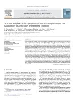
At
the
beginning,
a
small
endothermic
peak
with
5.4%
weight
loss
can
be
observed,
which
is
mainly
attributed
to
the
evaporation
of
water
in
the
precursors.
In
the
temperature
range
of
100–400
◦
C,
an
obvious
endothermic
Fig.
1.
TGA–DTA
curves
of
the
precursor
of
P
0
.
Fig.
2.
XRD
patterns
of
the
samples:
(a)
the
precursor
of
P
0
,
(b)
P
0
.
peaks
centered
at
259.3
◦
C
can
be
found
in
DTA
curve.
Simultane-
ously,
a
faster
weight
loss
stage,
claimed
as
25.8%
can
be
observed
in
TGA
curve.
The
thermal
decomposition
processes
can
be
ascribed
to
the
decomposition
and
oxidation
of
the
precursor
by
the
releasing
of
water
and
carbon
dioxide.
Therefore,
the
annealing
temperature
was
chosen
at
300
◦
C
to
obtain
the
final
products.
The
purity
and
crystalline
phase
of
P
0
and
the
precursor
of
P
0
were
determined
by
XRD.
Fig.
2(a)
showed
the
XRD
patterns
of
the
precursor.
As
a
comparison,
the
XRD
pattern
of
ZnO
product
(P
0
)
after
calcination
was
also
presented
(Fig.
2(b)).
The
diffraction
peaks
in
Fig.
2(a)
can
be
identified
as
the
Zn
4
(CO
3
)(OH)
6
H
2
O,
which
was
consistent
with
JCPDS
Card
No.11-0287.
While,
the
diffraction
peaks
of
P
0
can
be
identified
as
pure
hexagonal
ZnO
(JCPDS
Card
No.
36-1451).
The
XRD
patterns
of
P
0
and
the
precursor
are
con-
sistent
with
our
previous
results
with
no
sucrose
added
synthesis
procedure
[19].
It
shows
that
the
sucrose
as
complexing
agent
will
not
influence
the
formation
of
the
precursor
(Zn
4
(CO
3
)(OH)
6
H
2
O)
and
the
final
product
ZnO.
In
the
synthesis
process,
sucrose
was
introduced
into
the
urea
hydrothermal
procedure.
To
clarify
the
role
of
sucrose
acting
in
the
crystal
growth,
FTIR
spectra
were
measured
to
verify
the
possi-
ble
intermediate
by-products
and
the
results
were
shown
in
Fig.
3.
We
found
that
sucrose
played
the
roles
of
complexing
agent
and
fuel
in
the
synthesis
process.
In
acidic
solution,
the
sucrose
firstly
hydrolyzes
into
glucose
and
fructose,
which
can
be
further
oxidized
into
saccharic
acid,
glycolic
acid
and
trihydroxy-butyric
acid
with
a
large
number
of–COOH
and–OH
groups.
Furthermore,
the
COOH
groups
can
easily
combine
with
metal
ions
in
the
solution,
which
is
quite
similar
to
the
citric
acid
complexing
mechanisms.
W.
Lv
et
al.
/
Applied
Surface
Science
259 (2012) 557–
561 559
Fig.
3.
FTIR
spectra
of
samples
(a)
sucrose
(b)
the
precursor
of
P
0
(c)
calcined
at
300
◦
C
(P
0
).
Fig.
3(a)
shows
the
FTIR
spectrum
of
sucrose
and
its
typical
absorptions
are
in
agreement
with
the
spectrum
in
database
[18].
It
is
worth
noticing
that
no
obvious
absorption
is
present
between
1500
cm
−1
and
2500
cm
−1
.
While,
the
spectrum
for
the
precursor
of
P
0
shown
in
Fig.
3(b)
clearly
shows
the
coordinated
COO
−
sym-
metric
stretching
with
broad
absorption
around
1618
cm
−1
,
which
comes
from
the
products
of
the
sucrose
hydrolyzation
[20].
Consid-
ering
the
complexing
ability
mentioned
above,
it
can
be
identified
that
the
metal
ions
are
well
complexed
by
the
COOH
groups,
form-
ing
stable
COOZn
2+
.
And
in
fact,
no
precipitation
was
observed
during
the
stirring.
Moreover,
the
broad
absorption
band
centered
at
3400
cm
−1
can
be
observed
due
to
the
OH
stretching
vibration,
which
can
be
attributed
to
the
existence
of
crystallization
water
in
the
precursor.
The
absorption
band
around
1385
cm
−1
is
typ-
ical
asymmetric
stretching
vibration
of
NO
3
−
,
which
comes
from
the
raw
material
Zn(NO
3
)
2
.
After
calcination
at
300
◦
C
(Fig.
3c),
the
chelating
complexes
decomposed
and
a
mass
of
gases
are
gener-
ated,
which
are
favored
for
the
formation
of
porous
product.
As
curve
(b)
showed,
in
infrared
absorption
spectra
of
the
precursor,
the
absorption
peak
at
1048
cm
−1
,
830
cm
−1
,
711
cm
−1
are
ascribed
to
CO
3
2−
lattice
vibration
induced
infrared
absorption.
Therefore,
the
FTIR
shows
the
precursor
is
the
Zn
4
(CO
3
)(OH)
6
H
2
O,
which
is
consistent
with
the
XRD
results.
After
annealing
at
300
◦
C,
the
infrared
absorption
spectra
(Fig.
3(c))
shows
that
a
new
absorption
peak
centered
at
474
cm
−1
appears,
indicating
the
formation
of
ZnO
and
the
complete
decomposition
of
the
precursors.
Fig.
4(a)
shows
the
typical
SEM
images
of
the
products
after
annealing
at
300
◦
C.
Obviously,
the
hierarchical
structure
was
con-
structed
by
large
quantities
of
fluffy
nanosheetes
with
a
uniform
size
distribution
of
micro-flowers.
The
enlarge
view
of
the
P
0
in
Fig.
4(b)
shows
that
the
diameter
of
ZnO
flowers
is
about
10
m.
The
nanosheets
petals
are
narrow
in
width
and
ended
with
a
sharp
tip.
The
abundance
of
petals
will
greatly
increase
the
con-
tact
area
between
the
catalysts
and
organic
dyes.
Moreover,
the
gap
formed
by
the
adjacent
nanosheets
would
enhance
the
absorption
of
exciting
light
and
promote
the
photocatalytic
activities
of
ZnO.
The
optical
absorption
efficiency
increased
by
the
diffuse
reflec-
tion
happens
among
the
petals,
as
shown
in
the
inserted
figure
of
Fig.
4(b).
On
the
other
hand,
the
microstructure
of
the
nanosheets
petals
also
shows
differences
between
sucrose
adding
sample
P
0
and
no
sucrose
adding
one
S
0
.
The
high
magnification
SEM
images
of
petals
from
S
0
and
P
0
were
shown
in
Fig.
4(c,
d).
Apparently,
the
pores
on
the
nanosheets
are
quite
distinguished
from
each
other.
The
microstructure
of
S
0
presents
that
the
pores
are
embedded
in
the
petals,
like
large
number
of
holes
on
a
flat
surface.
While,
for
the
sucrose
added
sample
P
0
,
the
pores
were
formed
by
the
Fig.
4.
SEM
images.
(a)
Flower-like
ZnO
of
P
0
.
(b)
An
enlarge
view
of
P
0
.
The
inserted
shows
the
abridged
general
view
of
the
possible
light
absorption
in
the
sample
P
0
.
(c)
The
microstructure
of
S
0
(d)
the
microstructure
of
P
0
.
560 W.
Lv
et
al.
/
Applied
Surface
Science
259 (2012) 557–
561
Fig.
5.
Photodegradation
of
MO
in
the
solution
with
S
0
and
P
0
ZnO
flowers.
connection
of
a
great
quantities
of
ZnO
nanoparticles
presenting
larger
surface
areas
compared
with
S
0
.
In
fact,
there
is
no
obvi-
ous
difference
in
the
flowerlike
status
between
the
precursors
of
P
0
and
S
0
,
indicating
that
the
sucrose
effects
on
the
morphology
of
LBZC
(Zn
4
(CO
3
)(OH)
6
H
2
O)
is
not
obvious.
However,
to
gain
the
final
ZnO
hierarchical
structures,
annealing
process
was
carried
out
and
the
role
of
sucrose
was
activated
during
the
decomposition
of
LBZC.
In
the
process
of
synthesis,
the
sucrose
hydrolyzes
into
two
kinds
of
monosaccharides,
glucose
and
fructose
that
is
homodis-
perse
in
the
Zn
4
(CO
3
)(OH)
6
H
2
O
and
assist
combustion
during
the
annealing.
Considering
the
sucrose
can
be
used
as
fuel
in
the
fab-
rication
of
oxides,
the
high
temperature
decomposition
process
of
LBZC
with
sucrose
adding
can
be
treated
as
a
more
intensive
and
rapid
combustion,
leading
to
the
precursor
burning
much
more
sufficiently
and
the
crystallinity
of
ZnO
particles
improved.
Good
crystalline
quality
can
be
reflected
from
the
micro
structure
of
sam-
ples.
Spherical
nanoparticles
constituting
the
resultant
nanosheets
were
formed
by
the
additional
heating
from
the
added
sucrose,
which
would
be
beneficial
to
the
photocatalytic
activity.To
evaluate
the
sucrose
effects
on
the
photocatalytic
activity,
the
performances
of
S
0
and
P
0
were
investigated
by
the
degradation
of
MO
dye
under
UV
irradiation.
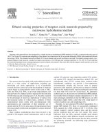
Fig.
5
compares
the
photodegradation
of
MO
as
a
function
of
irradiation
time
for
the
P
0
and
S
0
samples.
As
clearly
shown,
after
irradiation
for
100
min,
the
photocatalytic
degradation
of
MO
on
S
0
is
80%.
In
fact,
we
have
discussed
the
superior
photocat-
alytic
properties
of
the
multi-layered
mesoporous
ZnO
structures
(S
0
)
decomposing
the
MO,
which
showed
the
superior
photocat-
alytic
activity
to
the
commercial
ZnO
19
.
Surprisingly,
in
comparison
with
the
S
0
,
a
small
amount
of
sucrose
adding
sample
P
0
displayed
much
higher
decomposition
efficiency
with
a
degradation
rate
of
nealy
100%
after
irradiation
for
80
min.
Considering
the
differences
in
the
synthesized
procedure,
sucrose
adding
plays
an
important
role
in
improving
the
photocatalytic
properties.
The
surface
sensitive
diagnostic
test
XPS
was
conducted
to
elu-
cidate
the
oxidation
states
of
S
0
and
P
0
.
Fig.
6
demonstrates
the
high-resolution
XPS
spectra
of
O1s
states
of
sample
S
0
and
P
0
.
Obvi-
ously,
the
XPS
spectra
of
O1s
peaks
is
asymmetric
and
broadening,
which
can
be
resolved
into
two
peaks
by
a
Gaussian
distribution
fitting
centered
at
530.1
±
0.2
eV
and
531.7
±
0.2
eV,
respectively.
The
fitting
indicates
that
at
least
two
oxygen
species
are
present
in
the
near-surface
region.
O
A
signal
peaks
are
centered
at
530.1
±
0.2
eV
is
due
to
oxygen
in
the
wurtzite
structure
of
ZnO
(lattice
oxygen),
and
the
intensity
of
this
peak
is
a
measure
of
fully
oxidized
oxygen
atoms
[24].
O
B
signal
526
528
530 53
2
534
(a)
S
0
Intensity (a.u.)
Bindin
g Energ
y (e
V)
O1s Scan
B
O1s Scan
A
526 52
8
530
532
534
(b)
P
0
Intensity (a.u.)
Binding En
ergy (eV)
O1s Scan A
O1s Sc
an B
Fig.
6.
The
high-resolution
XPS
spectra
of
O1s
states
of
sample
S
0
(a)
and
P
0
(b).
peaks
at
531.7
±
0.2
eV
corresponds
to
the
adsorbed
oxygen,
which
is
ascribed
to
the
presence
of
adsorbed
oxygen,
including
hydroxyl
and
carbonate
groups
adsorbed
on
the
material
surface.[25–28]
The
integrated
intensity
of
peak
O
A
can
be
compared
with
that
of
peak
O
B
using
the
O
A
to
O
B
integrated
intensity
ratio
“X,”
which
was
approximately
2.0
and
1.7
for
P
0
and
S
0
,
respectively.
Apparently,
the
lattice
oxygen
in
the
sucrose
added
sample
P
0
is
higher
than
that
of
sample
S
0
.
This
result
also
indicates
that
the
crystallinity
of
P
0
is
superior
to
S
0
due
to
the
added
sucrose
providing
with
more
energy
during
annealing.
Under
the
UV
excitation,
electron-hole
pairs
carried
out
redox
reaction
and
more
surface
defects
will
be
companied
with
higher
combination
probability
of
surface
states
and
hole.
However,
the
high
crystallinity
would
decrease
surface
defects
and
the
combination
probability
of
surface
states
and
holes
that
can
enhance
photocatalytic
activity.
[5,6]
Considering
the
pho-
tocatalytic
activity
of
P
0
and
S
0
,
the
sucrose
induced
crystallinity
improvement
is
an
effective
treatment
to
increase
the
photoactiv-
ity
of
ZnO
photocatalysts.In
order
to
find
the
relationship
between
the
amount
of
sucrose
and
the
photocatalytic
activity
of
ZnO,
vari-
able
amount
of
sucrose
added
samples
were
prepared
through
the
similar
process.
Fig.
7
shows
the
plot
of
the
decolorization
efficien-
cies
of
MO
by
the
ZnO
with
variable
sucrose
after
40
min
reaction
time.
It
can
be
seen
that
no
sucrose
added
ZnO
S
0
show
nearly
60%
decolorization
efficiency.
With
the
sucrose
added,
ZnO
samples
showed
much
better
photocatalytic
activity
and
the
decolorization
efficiencies
were
greatly
increased.
As
shown
in
Fig.
7,
P
0
shows
the
superior
photocatalytic
activity
and
decolorization
efficiency
was
achieved
95%.
While,
other
ZnO
sample
with
fewer
or
more
sucrose
W.
Lv
et
al.
/
Applied
Surface
Science
259 (2012) 557–
561 561
Fig.
7.
Photocatativity
comparison
of
ZnO
flowers
after
MO
degradation
for
40
min.
The
sucrose
contents
of
S
0
,
P
−2
,
P
−1
,
P
0
,
P
1
,
P
2
were
0
g,
0.04
g,
0.06
g
0.08
g
0.1
g
and
0.25
g,
respectively.
added
show
lower
decolorization
efficiencies
during
the
same
reac-
tion
time.
Since
the
small
amount
of
sucrose
added
can
result
in
negligible
effects
on
the
morphology,
the
crystallinity
and
agglom-
eration
of
photocatalysts
should
be
considered.
In
some
cases,
it
was
found
that
the
heat
generated
during
the
reaction
could
be
more
prominent
to
cause
sintering
or
agglomeration
of
particles,
resulting
in
grain
growth
and
low
photocatalytic
reaction
sites.
Therefore,
the
optimization
of
reaction
condition
was
established
for
0.08
g
sucrose
added
ZnO
flowers.
4.
Conclusion
In
this
study,
hierarchical
structures
ZnO
was
successfully
syn-
thesized
via
a
sucrose
added
urea
hydrothermal
method.
The
prepared
ZnO
flowers
were
characterized
by
TG-DTA,
FTIR,
XRD
and
SEM.
The
photocatalytic
activities
of
ZnO
flowers
were
evalu-
ated
by
the
degradation
of
MO
and
results
show
that
the
sucrose
added
sample
presents
superior
decolorization
efficiency.
The
XPS
analysis
reflected
that
the
adding
of
sucrose
can
improve
the
crystallization
of
ZnO.
The
ZnO
flowers
synthesized
via
variable
sucrose
amount
were
also
estimated
by
the
decolorization
effi-
ciency
of
MO
after
40
min
reaction
time.
It
was
found
that
higher
sucrose
added
would
induce
a
slightly
reduction
effect
on
the
photocatalytic
activities
and
the
optimized
reaction
condition
was
estimated.
Acknowledgments
This
work
was
partly
supported
by
the
National
Natural
Science
Foundation
of
China
(No.
51102069).
This
work
was
also
supported
by
Heilongjiang
Education
Department
(12511164)
and
Innovative
Talents
Fund
of
Harbin
(2010RFQXG034).
References
[1]
Z.L.
Wang,
Materials
Science
and
Engineering
Reports
64
(2009)
33–71.
[2]
H.Q.
Wang,
G.H.
Li,
L.C.
Jia,
G.Z.
Wang,
C.J.
Tang,
Journal
of
Physical
Chemistry
C
112
(2008)
11738–11743.
[3]
Q.Z.
Wu,
X.
Chen,
P.
Zhang,
Y.C.
Han,
X.M.
Chen,
Y.H.
Yan,
S.P.
Li,
Crystal
Growth
&
Design
8
(2008)
3010–3018.
[4]
X.F.
Zhou,
D.Y.
Zhang,
Y.
Zhu,
Y.Q.
Shen,
X.F.
Guo,
W.P.
Ding,
Y.
Chen,
Journal
of
Physical
Chemistry
B
110
(2006)
25734–25739.
[5]
Q.H.
Zhang,
L.
Gao,
J.K.
Guo,
Applied
Catalysis
B:
Environmental
26
(2000)
207–215.
[6] D.
Li,
H.
Haneda,
Chemosphere
51
(2003)
129–137.
[7]
J.
Wang,
X.M.
Fan,
K.
Tian,
Z.W.
Zhou,
Y.
Wang,
Applied
Surface
Science
257
(2011)
7763–7770.
[8]
S.
Cho,
S.H.
Jung,
K.H.
Lee,
Journal
of
Physical
Chemistry
C
112
(2008)
12769–12776.
[9]
J.M.
Jang,
S.D.
Kim,
H.M.
Choi,
J.Y.
Kim,
W.G.
Jung,
Materials
Chemistry
and
Physics
113
(2009)
389–394.
[10]
S.J.
Henley,
M.N.R.
Ashfold,
D.P.
Nicholls,
P.
Wheatley,
D.
Cherns,
Applied
Physics
A:
Materials
Science
&
Processing
79
(2004)
1169–1173.
[11]
D.F.
Zhang,
L.D.
Sun,
J.
Zhang,
Z.G.
Yan,
C.H.
Yan,
Crystal
Growth
and
Design
8
(2008)
3609–3615.
[12]
X.F.
Zhou,
Z.L.
Hu,
Y.Q.
Fan,
S.
Chen,
W.P.
Ding,
N.P.
Xu,
Journal
of
Physical
Chemistry
C
112
(2008)
11722–11728.
[13]
F.
Xu,
Z.Y.
Yuan,
G.H.
Du,
M.
Halasa,
B.L.
Su,
Applied
Physics
A:
Materials
Science
&
Processing
86
(2007)
181–185.
[14] K.
Kakiuchi,
E.
Hosono,
T.
Kimura,
H.
Imai,
S.
Fujihara,
Journal
of
Sol-Gel
Science
and
Technology
39
(2006)
63–72.
[15]
S.
Bose,
S.K.
Saha,
Journal
of
the
American
Ceramic
Society
86
(2003)
1055–1057.
[16] S.
Bose,
Y.
Wu,
Journal
of
the
American
Ceramic
Society
88
(2005)
1999–2002.
[17]
Y.
Wu,
A.
Bandyopadhyay,
S.
Bose,
Materials
Science
and
Engineering
A
380
(2004)
349–355.
[18] />[19] L.L.
Xu,
Z.M.
Li,
Q.H.
Cai,
H.X.
Wang,
H.
Gao,
W.
Lv,
J.
Liu,
CrystEngComm
12
(2010)
2166–2171.
[20]
H.R.
Philipp,
L.M.
Levinson,
Journal
of
Applied
Physics
47
(1976)
1112–1122.
[21] J.P.
Liu,
X.T.
Huang,
K.M.
Sulieman,
F.L.
Sun,
X.
He,
Journal
of
Physical
Chemistry
B
110
(2006)
10612–10618.
[22]
P.L.
Zhu,
J.W.
Zhang,
Z.S.
Wu,
Z.J.
Zhang,
Crystal
Growth
&
Design
8
(2008)
3148–3153.
[23] H.Y.
Yin,
Z.D.
Xu,
Q.S.
Wang,
J.Y.
Bai,
H.H.
Bao,
Materials
Chemistry
and
Physics
91
(2005)
130–133.
[24]
Q.
Ma,
A.
Ogino,
T.
Matsuda,
K.
Shinji,
M.
Nagatsu,
Thin
Solid
Films
518
(2010)
3517.
[25] L.Q.
Jing,
F.L.
Yuan,
H.G.
Hou,
B.F.
Xin,
W.M.
Cai,
H.G.
Fu,
Science
in
China
Series
B:
Chemistry
48
(2005)
25–30.
[26]
M.
Alvarez,
T.
Lopez,
J.A.
Odriozola,
M.A.
Centeno,
M.I.
Domınguez,
M.
Montesd,
P.
Quintana,
D.H.
Aguilar,
R.D.
Gonza
ˇ
ılez,
Applied
Catalysis
B:
Environmental
73
(2007)
34–41.
[27]
J.J.
Benitez,
M.A.
Centeno,
J.A.
Odriozola,
R.
Conanec,
R.
March,
Y.
Laurent,
Catal-
ysis
Letters
34
(1995)
379.
[28]
M.J.
Capitan,
M.A.
Centeno,
P.
Malet,
I.
Carrizosa,
J.A.
Odriozola,
A.
Marquez,
J.F.
Sanz,
Journal
of
Physical
Chemistry
99
(1995)
4655.