Chapter 4 design for single reactions
Bạn đang xem bản rút gọn của tài liệu. Xem và tải ngay bản đầy đủ của tài liệu tại đây (2.13 MB, 21 trang )
Chapter 4. Design for Single Reactions
The reactor system selected will influence the economics of the process by
dictating the size of the units needed and by fixing the ratio of products (product
distribution) formed.
For single reactions, product distribution is fixed; hence, the important factor in
comparing designs is the reactor size.
1. Size comparision of single reactors
1.1. Mixed versus plug flow reactors: first- and second-order reactions
The ratio of sizes of mixed and plug flow reactors will depend on the extent of
reaction, the stoichiometry, and the form of the rate equation.
For the general case, a comparison of Eqs. 3.9 and 3.14 will give this size ratio.
Let us make this comparison for the reactions with the nth-order rate law:
(4.1)
where n varies anywhere from zero to three.
1
Chapter 4. Design for Single Reactions
For mixed flow, Eq. 3.9 gives
(4.2)
whereas for plug flow, Eq. 3.14 gives
(4.3)
Dividing Eq. 4.2 by Eq. 4.3 gives
(4.4)
2
Chapter 4. Design for Single Reactions
With constant density, or ε = 0, this expression integrates to
(4.5)
or
Equations 4.4 and 4.5 are displayed in graphical form in Fig. 4.1 to provide a
quick comparison of the performance of plug flow with mixed flow reactors.
3
Chapter 4. Design for Single Reactions
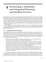
Figure 4.1
Comparison of
performance of
single mixed flow
and plug flow
reactors for the nthorder reactions
4
Chapter 4. Design for Single Reactions
Figure 4.1 shows the following:
1. For any particular duty and for all positive reaction orders the mixed reactor
is always larger than the plug flow reactor. The ratio of volumes increases with
reaction order.
2. When conversion is small, the reactor performance is only slightly affected
by flow type. The performance ratio increases very rapidly at high conversion;
consequently, a proper representation of the flow becomes very important in this
range of conversion.
3. Density variation during reaction affects design; however, it is normally of
secondary importance compared to the difference in flow type.
5
Chapter 4. Design for Single Reactions
1.2 Variation of Reactant Ratio for Second-Order Reactions
Second-order reactions of two components:
behaves as second-order reactions of one component when the reactant ratio is
unity. Thus
When a large excess of reactant B is used then its concentration does not change
appreciably (CB ~ CBO) and the reaction approaches first-order behavior with
respect to the limiting component A, or
Thus in Fig. 4.1, and in terms of the limiting component A, the size ratio of
mixed to plug flow reactors is represented by the region between the first-order
and the second-order curves.
6
Chapter 4. Design for Single Reactions
2. Multiple-reactor systems
2.1. Plug flow reactors in series and/or in parallel
• Consider N plug flow reactors connected in series,
• X1, X2, . . . , XN is the fractional conversion of component A leaving reactor 1,
2, . . . , N.
Basing the material balance on the feed rate of A to the first reactor, we find for
the ith reactor from Eq. 3.15
(4.6)
or for the N reactors in series
(4.7)
7
Chapter 4. Design for Single Reactions
Hence, N plug flow reactors in series with a total volume V gives the same
conversion as a single plug flow reactor of volume V.
2.2. Equal-size mixed flow reactors in series
In plug flow, the concentration of reactant decreases progressively through the
system; in mixed flow, the concentration drops immediately to a low value.
Consider a system of N mixed flow reactors connected in series:
• The concentration is uniform in each reactor,
• The concentration changes as fluid moves from reactor to reactor.
This stepwise drop in concentration, illustrated in Fig. 4.2, suggests that the larger
the number of units in series, the closer should the behavior of the system
approach plug flow.
8
Chapter 4. Design for Single Reactions
Figure 4.2 Concentration profile through an N-stage mixed flow reactor
system compared with single flow reactors.
9
Chapter 4. Design for Single Reactions
Evaluate the behavior of a series of N equal-size mixed flow reactors. Density
changes will be assumed to be negligible; hence ε = 0 and t = τ.
Figure 4.3 Notation for a system of N equal-size mixed reactors in series.
First-Order Reactions:
For component A about vessel i, it can be written:
(4.8)
10
Chapter 4. Design for Single Reactions
Because ε = 0 this may be written in terms of concentrations:
(4.9)
Or
(4.10)
The space-time r (or mean residence time t) is the same in all the equal-size
reactors of volume Vi. Therefore,
(4.11)
Rearranging Eq. 4.11 gives for the system:
(4.12)
11
Chapter 4. Design for Single Reactions
For N ∞, this equation reduces to the plug flow equation
(4.13)
With Eqs. 4.12 and 4.13 we can compare performance of N reactors in series with
a plug flow reactor or with a single mixed flow reactor. This comparison is shown
in Fig. 4.4 for first-order reactions in which density variations are negligible.
12
Chapter 4. Design for Single Reactions
Figure 4.4 Comparison of performance of a series of N equal-size mixed flow
reactors with a plug flow reactor for the first-order reaction.
13
Chapter 4. Design for Single Reactions
Second-Order Reactions
Consider reaction:
N reactors in series:
(4.14)
Whereas for plug flow:
(4.15)
A comparison of the performance of these reactors is shown in Fig. 4.5.
14
Chapter 4. Design for Single Reactions
Figure 4.5 Comparison
of performance of a
series of N equal-size
mixed flow reactors
with a plug flow reactor
for elementary secondorder reactions
15
Example
1. At present 90% of reactant A is converted into product by a second-order reaction
in a single mixed flow reactor. We plan to place a second reactor similar to the
one being used in series with it.
(a) For the same treatment rate as that used at present, how will this addition
affect the conversion of reactant?
(b) For the same 90% conversion, by how much can the treatment rate be increased?
2. The following liquid-phase hydration reaction occurs in a 10,000 L CSTR:
A+H2O → B
with a first-order rate constant of 2.5 x 10⁻³ min-1.
a) What is the steady-state fractional conversion of A if the feed rate is 0.3 L/sec and
the feed concentration CAo = 0.12 mol/L?
b) If the feed rate suddenly drops to 70% of its original value and is maintained there,
what is the fractional conversion of A after 60 minutes, and what is the new
steady state fractional conversion?
16
Chapter 4. Design for Single Reactions
2.3 Mixed Flow Reactors of Different Sizes in Series
2.3.1 Finding the Conversion in a Given System
Consider three mixed flow reactors in series as shown in Figure 4.6.
Figure 4.6 Notation for a series of unequal-size mixed flow reactors.
17
Chapter 4. Design for Single Reactions
Noting that ε = 0, it can be written for component A in the first reactor:
(4.16)
or
(4.17)
Similarly, for the ith reactor we may write:
(4.18)
18
Chapter 4. Design for Single Reactions
4.18)
4.18)
Figure 4.7 Graphical procedure for finding compositions in a series
of mixed flow reactors.
19
Chapter 4. Design for Single Reactions
2.3.2 Determining the Best System for a Given Conversion
Suppose we want to find the minimum size of two mixed flow reactors in series to
achieve a specified conversion of feed which reacts with arbitrary but known
kinetics. It can be written for component A in the first and second reactor:
and
(4.19)
These relationships are displayed in Fig. 4.8 for two alternative reactor
arrangements, both giving the same final conversion X2. Figure 4.8 shows that the
total reactor volume is as small as possible (total shaded area is minimized) when
the rectangle KLMN is as large as possible.
20