- Trang chủ >>
- Khoa Học Tự Nhiên >>
- Vật lý
Tài liệu Open channel hydraulics for engineers. Chapter 4 non uniform flow ppt
Bạn đang xem bản rút gọn của tài liệu. Xem và tải ngay bản đầy đủ của tài liệu tại đây (270.64 KB, 20 trang )
OPEN CHANNEL HYDRAULICS FOR ENGINEERS
-----------------------------------------------------------------------------------------------------------------------------------
-----------------------------------------------------------------------------------------------------------------------------------
Chapter 4: NON-UNIFORM FLOW
70
Chapter
NON-UNIFORM FLOW
_________________________________________________________________________
4.1. Introduction
4.2. Gradually-varied steady flow
4.3. Types of water surface profiles
4.4. Drawing water surface profiles
_________________________________________________________________________
Summary
Linking up with Chapter 2, dealing with uniform flow in open channels, it may be noted
that any change in the flow phenomenon (i.e. flow rate, velocity, flow depth, flow area,
bed slope do not remain constant) causes the flow to be non-uniform. This chapter will
discuss the effect of change in any one of the above quantities, including specific energy,
critical depth and slope, and flow types. How to draw water surface profiles will also be
introduced.
Key words
Non-uniform; specific energy; critical; gradually-varied steady flow; water surface profiles
_________________________________________________________________________
4.1. INTRODUCTION
4.1.1. General
In the previous Chapter 2, the flow was uniform under all circumstances under
consideration. In many situations the flow in an open channel is not of uniform depth along
the channel. In this chapter the flow conditions studied relate to steady, but non-uniform,
flow. This type of flow is created by, among other things, the following major causes:
Changes in the channel cross-section.
Changes in the channel slope.
Certain obstructions, such as dams or gates, in the stream’s path.
Changes in the discharge – such as in a river, where tributaries enter the main
stream.
A non-uniform flow is characterized by a varied depth and a varied mean flow velocity:
0
s
V
or
h
0
s
(4-1)
If the bottom slope and the energy line slope are not equal, the flow depth will vary along
the channel, either increasing or decreasing in the flow direction. Physically, the difference
between the component of weight and the shear forces in the direction of flow produces a
change in the fluid momentum which requires a change in velocity and, from continuity
considerations, a change in depth. Whether the depth increases or decreases depends on
various parameters of the flow, with many types of surface profile configurations possible.
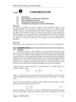
Fig. 4.1. illustrates some typical longitudinal free-surface profiles. Upstream and
downstream controls can induce various flow patterns. In some cases, a hydraulic jump
might take place. A jump is a rapid-varied flow phenomenon; calculations were developed
in Chapter 3. However, it is also a control section and it affects the free surface profiles
upstream and downstream.
OPEN CHANNEL HYDRAULICS FOR ENGINEERS
-----------------------------------------------------------------------------------------------------------------------------------
-----------------------------------------------------------------------------------------------------------------------------------
Chapter 4: NON-UNIFORM FLOW
71
Fig. 4.1. Examples of non-uniform flow
4.1.2. Accelerated and Retarded flow
An idealized section of a reach of a channel with accelerated and retarded flow
conditions is shown in Fig. 4.2a and Fig. 4.2b, respectively. As flow accelerates, with the
rate of flow constant, the depth h must decrease form point 1 to point 2, and a water
surface profile as shown in Fig. 4.2a results. Retarded flow will produce water surface
profiles as shown in Fig. 4.2b.
Significant in each one of the above cases is the fact that now the water surface is a curved
line and not longer parallel to the channel bottom and the energy line, as was the case for
uniform flow. The following points are made in connection with the above observations.
upstream control
downstream control
control
sluice
gate
rapid
varied
flow
hydraulic jump
sharp-crested
weir
rapid
varied
flow
rapid
varied
flow
gradually
varied
flow
gradually
varied
flow
upstream control
downstream
control
hydraulic
jump
supercritical
flow
subcritical
flow
critical
depth
overflow
(critical depth)
control
h
c
h
c
rapid
varied
flow
rapid
varied
flow
rapid
varied
flow
gradually
varied
flow
gradually
varied
flow
OPEN CHANNEL HYDRAULICS FOR ENGINEERS
-----------------------------------------------------------------------------------------------------------------------------------
-----------------------------------------------------------------------------------------------------------------------------------
Chapter 4: NON-UNIFORM FLOW
72
The water surface, as will be shown later, can have a concave or a convex shape.
The energy line is not necessarily a straight line; however, it is assumed that the
energy gradient is constant along the length of a reach and the energy line will be
represented and considered to have a slope i
e
= H
L
/L.
As was done in the case of uniform flow, it is here also accepted that the depth of
flow, h, is equal to the pressure head in the energy equation. Obviously, this applies
only when the slope of the channel bottom is small. For very steep slopes,
allowances for this discrepancy must be made.
i
L
z
1
z
2
water surface
H
L
1
1
p
h
2
2
p
h
2
1
V
2g
2
2
V
2g
energy-head line
hydraulic grade line
datum
Fig. 4.2a. Accelerated flow
i
L
z
1
z
2
water surface
H
L
1
1
p
h
2
2
p
h
2
1
V
2g
2
2
V
2g
energy-head line
hydraulic grade line
datum
Fig. 4.2b. Retarded flow
OPEN CHANNEL HYDRAULICS FOR ENGINEERS
-----------------------------------------------------------------------------------------------------------------------------------
-----------------------------------------------------------------------------------------------------------------------------------
Chapter 4: NON-UNIFORM FLOW
73
4.1.3. Equation of non-uniform flow
Fig. 4.3. Non-uniform flow
Consider a non-uniform flow in an open channel between section 1-1 and section 2-2, in
which the water surface has a rising trend (i.e. the energy-head gradient is less than the bed
slope) as shown in Fig. 4.3.
Let V = velocity of water at section 1-1;
h = depth of water at section 1-1;
V+dV = velocity of water at section 2-2;
h+dh = depth of water at section 2-2;
i
b
= slope of channel bed;
i
e
= slope of the energy grade line;
dl = distance between section 1-1 and section 2-2;
b = average width of the channel,
Q = discharge through the channel,
z
b
= change of bottom elevation between section 1-1 and section 2-2, and
h
e
= H
L
, change of energy grade line between section 1-1 and section 2-2.
Since the depth of water at section 2-2 is larger than at section 1-1, the velocity of water at
section 2-2 will be smaller than that at section 1-1.
Applying Bernoulli’s equation at section 1-1 and section 2-2:
2 2
b e
V (V dV)
z h (h dh) h
2g 2g
(4-2)
2
2
b e
V dV
V
i .dl h h dh i .dl
2g 2g
(4-3)
b e
V.dV
i .dl dh i .dl
g
, neglecting
2
(dV)
2g
(small of second order) (4-4)
or
b e
dh V.dV
i i
dl g.dl
(dividing by dl) (4-5)
1
1
2
2
i
e
i
b
dl
flow
h
e
water surface
2
V
2g
2
(V+dV)
2g
h
h+dh
z
b
OPEN CHANNEL HYDRAULICS FOR ENGINEERS
-----------------------------------------------------------------------------------------------------------------------------------
-----------------------------------------------------------------------------------------------------------------------------------
Chapter 4: NON-UNIFORM FLOW
74
b e
dh V.dV
i i
dl g.dl
(4-6)
We know that the quantity of water flowing per unit width is constant, therefore
q = V.h = constant (4-7)
dq
0
dl
(4-8)
or
d(Vh)
0
dl
(4-9)
Differentiating the above equation (treating both V and h as variables),
V.dh h.dV
0
dl dl
(4-10)
dV V dh
dl h dl
(4-11)
Substituting the above value of
dV
dl
in Eq. (4-6), yields
2
b e
dh V dh
i i
dl gh dl
(4-12)
2
b e
dh V
1 i i
dl gh
(4-13)
b e
2
i idh
dl
V
1
gh
(4-14)
Notes: The above relation gives the slope of the water surface with respect to the bottom
of the channel. Or in other words, it gives the variation of water depth with respect to the
distance along the bottom of the channel. The value of dh/dl (i.e. zero, positive or negative)
gives the following important information:
If dh/dl is equal to zero, it indicates that the slope of the water surface is equal to
the bottom slope. Or in other words, the water surface is parallel to the channel
bed.
If dh/dl is positive, it indicates that the water surface rises in the direction of flow.
The profile of water, so obtained, is called backwater curve.
If dh/dl is negative, it indicates that the water surface falls in the direction of flow.
The profile of water, so obtained, is called downward curve.
OPEN CHANNEL HYDRAULICS FOR ENGINEERS
-----------------------------------------------------------------------------------------------------------------------------------
-----------------------------------------------------------------------------------------------------------------------------------
Chapter 4: NON-UNIFORM FLOW
75
Example 4.1: A rectangular channel, 20 m wide and having a bed slope of 0.006, is
discharging water with a velocity of 1.5 m/s. The flow is regulated in such a way that the
slope of the water energy gradient is 0.0008. Find the rate at which the depth of water will
be changing at a point where the water is flowing 2 m deep.
Solution:
Given: width of the channel: b = 20 m
bed slope: i
b
= 0.006
velocity of water: V = 1.5 m/s
slope of energy line: i
e
= 0.0008
depth of water: h = 2 m
Let
dh
dl
be the rate of change of water depth. Using equation in (4-14):
b e
2
i idh
dl
V
1
gh
= 0.0059 Ans.
4.2. GRADUALLY-VARIED STEADY FLOW
4.2.1. Backwater calculation concept
Gradually varied flow is a steady, non-uniform flow in which the depth variation in
the direction of motion is gradual enough to consider the transverse pressure distribution as
being hydrostatic. This allows the flow to be treated as one-dimensional with no transverse
pressure gradients other than those due to gravity.
For subcritical flows the flow situation is controlled by the downstream flow conditions. A
downstream hydraulic structure (e.g. bridge piers, gate) will increase the upstream depth
and create a “backwater” effect. This concept has been introduced shortly in section 4.1.3.
The term “backwater calculation” refers more generally to the calculation of the
longitudinal free-surface profile for both subcritical and supercritical flows. The backwater
calculation is developed assuming:
a non-uniform flow
a steady flow
that the flow is gradually varied, and
that, at a given section, the flow resistance is the same as for a uniform flow with
the same depth and discharge, regardless of trends of the depth.
4.2.2. Equation of gradually-varied flow
In addition to the basic gradually-varied flow assumption, we further assume that
the flow occurs in a prismatic channel, or one that is approximately so, and that the slope
of the energy grade line can be evaluated from uniform flow formulas with uniform flow
resistance coefficients, using the local depth as though the flow were locally uniform.
Referring to Fig. 4.4., the total energy head at any cross-section is
OPEN CHANNEL HYDRAULICS FOR ENGINEERS
-----------------------------------------------------------------------------------------------------------------------------------
-----------------------------------------------------------------------------------------------------------------------------------
Chapter 4: NON-UNIFORM FLOW
76
2
V
H z h
2g
(4-15)
in which z = channel bed elevation; h = water depth, = kinetic-energy correction
coefficient as introduced in Chapter 2, and V = mean flow velocity.
Fig 4.4. Definition sketch for gradually-varied flow
If this expression for H is differentiated with respect to x, the coordinate in the flow
direction, the following equation is obtained:
dx
dE
ii
dx
dH
be
with
2
V
E h
2g
(4-16)
in which i
e
is defined as the slope of the energy grade line; i
b
is the bed slope (= - dz/dx);
and E is the specific-energy head (i.e. the energy head with respect to the bottom). Solving
for dE/dx gives the first form of the equation of gradually varied flow:
eb
ii
dx
dE
(4-17)
It appears from this equation that the specific-energy head can either increase or decrease
in the downstream direction, depending on the relative magnitudes of the bed slope and the
slope of the energy grade line. Yen (1973) showed that, in the general case, i
e
is not the
same as the friction slope i
f
(=
0
/R, this equation will be introduced again in Chapter 7)
or the energy dissipation gradient. Netherless, we have no better way of evaluating this
slope than applying uniform-flow formulas such as those of Manning or Chezy. It is
incorrect, however, to mix the friction slope, which clearly comes from a momentum
analysis, with terms involving , the kinetic-energy correction (Martin and Wiggert, 1975).
Note: The bed slope i
e
and the friction slope i
f
are defined as:
o
e f
z H
i = sin tan and i
x x R
respectively, where H is the mean total energy-head, z is the bed elevation, is the channel
slope and
o
is the bottom shear stress.
bed
h
2
V
2 g
z
slope of energy grade line, i
e
datum
dH
H
bed slope i
b
dx
OPEN CHANNEL HYDRAULICS FOR ENGINEERS
-----------------------------------------------------------------------------------------------------------------------------------
-----------------------------------------------------------------------------------------------------------------------------------
Chapter 4: NON-UNIFORM FLOW
77
The second form of the equation of gradually-varied flow can be derived if it is recognized
that
dE dE dh
dx dh dx
and that, applying equation (4-11),
2
dE
1 Fr
dh
, provided that the
Froude number is properly defined. Then, equation (4-17) becomes:
b e
2
i idh
dx 1 Fr
(4-18)
The definition of the Froude number in equation (4-18) depends on the channel geometry.
For a compound channel, it should be the compound-channel Froude-number, while for a
regular, prismatic channel, in which d/dh is negligible, it assumes the conventional
energy definition given by Q
2
B/gA
3
.
The ratio dh/dx in Eq. (4-18) represents the slope or the tangent to the water surface at any
point along the channel. This relationship therefore indicates whether at any point along
the channel the water surface is rising (backwater condition) or dropping (drawdown
condition). Immediately the following deductions can be made:
When
dh
0
dx
, the slope of the water surface is dropping in the downstream
direction and the depth decreases downstream.
When
dh
0
dx
, the slope of water surface is parallel to the channel bottom and
uniform flow exists. This can be readily seen from Eq. (4-18) since, for this
condition, i
b
= i
e
must equal zero.
When
dh
0
dx
, the slope of water surface rises in the downstream direction and the
depth h increases downstream.
When
dh
dx
, which requires that 1 – Fr
2
= 0 or Fr = 1, the slope of the water
surface must theoretically be vertical. This flow occurs when the flow changes
from subcritical to supercritical, or vice versa, as indicated by the value of the
Froude number. The formulas derived do not actually apply any longer due to the
assumptions made. A vertical water surface also does not occur in reality; however,
a very noticeable change in the water surface takes place. This is especially so
when the flow changes from below h
c
to above h
c
. In such instance a phenomenon
known as the hydraulic jump occurs.
4.3. TYPES OF WATER SURFACE PROFILES
4.3.1. Classification of flow profiles
From the foregoing, it is evident that the relationship expressed in Eq. (4-18)
provides a considerable amount of information as to the shape of the water surface profile
in an open channel. Investigation of this formula yields the following results: