Điện tử số part 4
Bạn đang xem bản rút gọn của tài liệu. Xem và tải ngay bản đầy đủ của tài liệu tại đây (1.87 MB, 185 trang )
4/1
©
R.Lauwereins
Imec 2001
Digital
design
Combina-
torial
circuits
Sequential
circuits
FSMD
design
VHDL
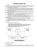
Course contents
•
Digital design
•
Combinatorial circuits: without status
•
Sequential circuits: with status
FSMD design: hardwired processors
•
Language based HW design: VHDL
4/2
©
R.Lauwereins
Imec 2001
Digital
design
Combina-
torial
circuits
Sequential
circuits
FSMD
design
VHDL
FSMD design
FSMDs
•
Models
•
Synthesis techniques
4/3
©
R.Lauwereins
Imec 2001
Digital
design
Combina-
torial
circuits
Sequential
circuits
FSMD
design
VHDL
FSMD
•
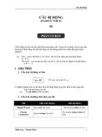
FSMD: Finite State Machine with Datapath
•
FSMD = hardcoded processor
Consists of a datapath that performs the
computations
and a controller which indicates to the
datapath which operations have to be carried
out on which data
The controller always executes the same
algorithm: hardcoded
•
A traditional ASIC consists of multiple
interconnected FSMDs
4/4
©
R.Lauwereins
Imec 2001
Digital
design
Combina-
torial
circuits
Sequential
circuits
FSMD
design
VHDL
FSMD
Datapath
Controller
Control
signals
Status
signals
Data
inputs
Data
outputs
Control
inputs
Control
outputs
4/5
©
R.Lauwereins
Imec 2001
Digital
design
Combina-
torial
circuits
Sequential
circuits
FSMD
design
VHDL
FSMD design
•
FSMDs
Datapath design
Controller design
•
Models
•
Synthesis techniques
4/6
©
R.Lauwereins
Imec 2001
Digital
design
Combina-
torial
circuits
Sequential
circuits
FSMD
design
VHDL
FSMD design
•
FSMDs
Datapath design
Controller design
•
Models
•
Synthesis techniques
4/7
©
R.Lauwereins
Imec 2001
Digital
design
Combina-
torial
circuits
Sequential
circuits
FSMD
design
VHDL
Datapath design
•
Datapath
Temporary storage: registers, register files,
FIFO’s, …
Functional units: arithmetic and logic units,
shifters
Connections: busses, multiplexors, tri-state bus
drivers
4/8
©
R.Lauwereins
Imec 2001
Digital
design
Combina-
torial
circuits
Sequential
circuits
FSMD
design
VHDL
Datapath design
∑
=
=
2
1i
i
xsum
Task:
sum = 0
FOR i = 1 TO 2
sum = sum + x
i
ENDFOR
y = sum
Algorithm:
Processing
Control
Datapath construction rules:
•
each variable and constant corresponds to a register
•
each operator corresponds to a functional unit
•
connect outputs of registers to input of functional
units; when multiple outputs connect to the same input:
MUX or bus with tristate drivers
•
connect output of functional units to input
of registers; when multiple outputs connect to the same
input: MUX or bus with tristate drivers
4/9
©
R.Lauwereins
Imec 2001
Digital
design
Combina-
torial
circuits
Sequential
circuits
FSMD
design
VHDL
Datapath design
sum = 0
FOR i = 1 TO 2
sum = sum + x
i
ENDFOR
y = sum
Algorithm:
Variables: sum
Reset
Load
Clk
Register
SUM
0
1
2
Wait
100
Add
Operators: add
x
i
Connections
Add2
010
Output
001
Add1
010
Start=1
y
0
Start
Output order:
‘Reset’,’Load’,
’Out’
210
4/10
©
R.Lauwereins
Imec 2001
Digital
design
Combina-
torial
circuits
Sequential
circuits
FSMD
design
VHDL
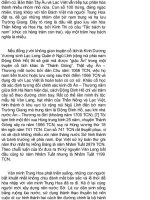
Datapath design
Task: count the number of ‘1’s in a word
Data = Inport || OCnt = 0 || Mask = 1
WHILE Data <> 0 DO
Temp = Data AND Mask
OCnt = OCnt + Temp || Data = Data >> 1
ENDWHILE
Outport = OCnt
Algorithm:
All instructions on a single line are executed concurrently:
maximum speed, but highest cost
Trading-off speed for area is explained in the section on
‘Synthesis techniques’
All hardware components work in parallel. Implementing
hardware is hence not writing a sequential software
program and implementing this directly in hardware. Above
algorithm is a ‘concurrent’ description!
4/11
©
R.Lauwereins
Imec 2001
Digital
design
Combina-
torial
circuits
Sequential
circuits
FSMD
design
VHDL
Datapath design
Data = Inport; OCnt = 0; Mask = 1
WHILE Data <> 0 DO
Temp = Data AND Mask
OCnt = OCnt + Temp; Data = Data >> 1
ENDWHILE
Outport = OCnt
0
1
2
3
4
5
Comp
x00000
Update
010100
Load
111x00
s=1
Temp
x00010
z=0
Out
x00001
z=1
s=0
s
Data
Data = Inport; OCnt = 0; Mask = 1
WHILE Data <> 0 DO
Temp = Data AND Mask
OCnt = OCnt + Temp; Data = Data >> 1
ENDWHILE
Outport = OCnt
OCnt
R
Data = Inport; OCnt = 0; Mask = 1
WHILE Data <> 0 DO
Temp = Data AND Mask
OCnt = OCnt + Temp; Data = Data >> 1
ENDWHILE
Outport = OCnt
Mask
Data = Inport; OCnt = 0; Mask = 1
WHILE Data <> 0 DO
Temp = Data AND Mask
OCnt = OCnt + Temp; Data = Data >> 1
ENDWHILE
Outport = OCnt
Temp
Data = Inport; OCnt = 0; Mask = 1
WHILE Data <> 0 DO
Temp = Data AND Mask
OCnt = OCnt + Temp; Data = Data >> 1
ENDWHILE
Outport = OCnt
<>0
Data = Inport; OCnt = 0; Mask = 1
WHILE Data <> 0 DO
Temp = Data AND Mask
OCnt = OCnt + Temp; Data = Data >> 1
ENDWHILE
Outport = OCnt
AND
Data = Inport; OCnt = 0; Mask = 1
WHILE Data <> 0 DO
Temp = Data AND Mask
OCnt = OCnt + Temp; Data = Data >> 1
ENDWHILE
Outport = OCnt
Add
Data = Inport; OCnt = 0; Mask = 1
WHILE Data <> 0 DO
Temp = Data AND Mask
OCnt = OCnt + Temp; Data = Data >> 1
ENDWHILE
Outport = OCnt
>>1
Data = Inport; OCnt = 0; Mask = 1
WHILE Data <> 0 DO
Temp = Data AND Mask
OCnt = OCnt + Temp; Data = Data >> 1
ENDWHILE
Outport = OCnt
Data = Inport; OCnt = 0; Mask = 1
WHILE Data <> 0 DO
Temp = Data AND Mask
OCnt = OCnt + Temp; Data = Data >> 1
ENDWHILE
Outport = OCnt
Data = Inport; OCnt = 0; Mask = 1
WHILE Data <> 0 DO
Temp = Data AND Mask
OCnt = OCnt + Temp; Data = Data >> 1
ENDWHILE
Outport = OCnt
Data = Inport; OCnt = 0; Mask = 1
WHILE Data <> 0 DO
Temp = Data AND Mask
OCnt = OCnt + Temp; Data = Data >> 1
ENDWHILE
Outport = OCnt
Data = Inport; OCnt = 0; Mask = 1
WHILE Data <> 0 DO
Temp = Data AND Mask
OCnt = OCnt + Temp; Data = Data >> 1
ENDWHILE
Outport = OCnt
Data = Inport; OCnt = 0; Mask = 1
WHILE Data <> 0 DO
Temp = Data AND Mask
OCnt = OCnt + Temp; Data = Data >> 1
ENDWHILE
Outport = OCnt
Data = Inport; OCnt = 0; Mask = 1
WHILE Data <> 0 DO
Temp = Data AND Mask
OCnt = OCnt + Temp; Data = Data >> 1
ENDWHILE
Outport = OCnt
Data = Inport; OCnt = 0; Mask = 1
WHILE Data <> 0 DO
Temp = Data AND Mask
OCnt = OCnt + Temp; Data = Data >> 1
ENDWHILE
Outport = OCnt
1 0
Inport
Data = Inport; OCnt = 0; Mask = 1
WHILE Data <> 0 DO
Temp = Data AND Mask
OCnt = OCnt + Temp; Data = Data >> 1
ENDWHILE
Outport = OCnt
zero
Data = Inport; OCnt = 0; Mask = 1
WHILE Data <> 0 DO
Temp = Data AND Mask
OCnt = OCnt + Temp; Data = Data >> 1
ENDWHILE
Outport = OCnt
Data = Inport; OCnt = 0; Mask = 1
WHILE Data <> 0 DO
Temp = Data AND Mask
OCnt = OCnt + Temp; Data = Data >> 1
ENDWHILE
Outport = OCnt
Data = Inport; OCnt = 0; Mask = 1
WHILE Data <> 0 DO
Temp = Data AND Mask
OCnt = OCnt + Temp; Data = Data >> 1
ENDWHILE
Outport = OCnt
Data = Inport; OCnt = 0; Mask = 1
WHILE Data <> 0 DO
Temp = Data AND Mask
OCnt = OCnt + Temp; Data = Data >> 1
ENDWHILE
Outport = OCnt
Outport
Data = Inport; OCnt = 0; Mask = 1
WHILE Data <> 0 DO
Temp = Data AND Mask
OCnt = OCnt + Temp; Data = Data >> 1
ENDWHILE
Outport = OCnt
Wait
x01x00
Data = Inport; OCnt = 0; Mask = 1
WHILE Data <> 0 DO
Temp = Data AND Mask
OCnt = OCnt + Temp; Data = Data >> 1
ENDWHILE
Outport = OCnt
Output order:
543210
4/12
©
R.Lauwereins
Imec 2001
Digital
design
Combina-
torial
circuits
Sequential
circuits
FSMD
design
VHDL
Datapath design
•
Possible optimisations:
When the life time of 2 variables is non-
overlapping, both can be stored in the same
register: register sharing
When two operations are not executed
concurrently, they can be assigned to the same
functional unit: functional unit sharing
When two connections are not used
concurrently, they can be shared: connection
sharing
When two registers are not concurrently read
from resp. writen to, they can be combined into
a single register file: register port sharing
Operations that could be executed
concurrently, may also be executed
sequentially, facilitating the four previous
optimisations
4/13
©
R.Lauwereins
Imec 2001
Digital
design
Combina-
torial
circuits
Sequential
circuits
FSMD
design
VHDL
Temporary storage
External input
External output
Result switching network
Datapath design
•
Generic structure of the datapath:
Functional units
Operand switching network
4/14
©
R.Lauwereins
Imec 2001
Digital
design
Combina-
torial
circuits
Sequential
circuits
FSMD
design
VHDL
Datapath design
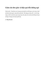
•
Typical datapath:
R
L
C
S
1 0
WA
WE
RA
1
RE
1
RA
2
RE
2
R
L
COE
RFOE
1
RFOE
2
ROE
AOE SOE
OOE
> = <
Counter
Register
File
2
3
Register
Comparator ALU Barrel
shifter
Outport
Inport
F
Sh
D
4/15
©
R.Lauwereins
Imec 2001
Digital
design
Combina-
torial
circuits
Sequential
circuits
FSMD
design
VHDL
Datapath design
•
In the datapath of previous slide a few
decisions have been taken:
Only 1 i.o. 2 result busses ⇒ ALU and Barrel
shifter cannot be used concurrently
Only 2 i.o. 4 operand busses ⇒ e.g. Compare
and ALU work on the same set of data
9 registers with only 2 write ports and 3 read
ports
Inport can only feed the register file
4/16
©
R.Lauwereins
Imec 2001
Digital
design
Combina-
torial
circuits
Sequential
circuits
FSMD
design
VHDL
Datapath design
OOESOEDSH0F0
RF
OE2
RE2RA0 SH1SH2AOEF1F2ROELRRA1RA2
Barrel
shifter
ALU
Register
Register File
Read Port 2
Instruction format
RF
OE1
RE1RA0RA1WA1R RA2WEWA0WA2SCOECL
Register File
Read Port 1
Register
File
Write Port
Counter
01234567891011121314151617
1819202122232425262728293031
32-bit instruction word
For reasons of simplicity, clarity and correctness, it is
possible to assign a mnemonic to a certain bit pattern
(e.g. ADD): assembly instruction
4/17
©
R.Lauwereins
Imec 2001
Digital
design
Combina-
torial
circuits
Sequential
circuits
FSMD
design
VHDL
Datapath design
•
The size of the instruction word may be
reduced, since several operations cannot
be executed concurrently
Either Register File Read Port 2, either Register
Read Port connects to the 1st Operand Bus (-1)
Either Register File Read Port 1, either Counter
Read Port connects to the 2nd Operand Bus (-1)
ALU & Shift cannot occur concurrently: 1 bit
needed to select the operator and 4 bits control
the operator (-2)
When the ALU operator is active, its output
may immediately be placed on the result bus;
idem for the Barrel shifter (-2)
For the counter the ‘Count’ and ‘Load’
operations are exclusive (-1)
•
Additional limitations to concurrency may
be introduced at the cost of increased
execution time
4/18
©
R.Lauwereins
Imec 2001
Digital
design
Combina-
torial
circuits
Sequential
circuits
FSMD
design
VHDL
Datapath design
•
Design freedom
Type Fixed To be designed speed cost design
time
custom
proc.
fixed
algo
- - custom
DP
custom
Ctrl
↑↑ ⇔ ↓↓ ↑↑
soft IP fixed
algo
DP - DP
ext.
custom
Ctrl
↑ ↔ ↓ ↑
ASIP algo
class
DP Ctrl DP
ext.
Ctrl
ext.
↓ ↔ ↑ ↓
µ
Proc any
algo
DP Ctrl - -
↓↓
-
↑↑ ↓↓
A compiler performs the same tasks as synthesis tools
(e.g. assign variables without overlapping life time to
the same register) but with less degrees of freedom,
since the hardware is fixed
4/19
©
R.Lauwereins
Imec 2001
Digital
design
Combina-
torial
circuits
Sequential
circuits
FSMD
design
VHDL
FSMD design
•
FSMDs
Datapath design
Controller design
•
Models
•
Synthesis techniques
4/20
©
R.Lauwereins
Imec 2001
Digital
design
Combina-
torial
circuits
Sequential
circuits
FSMD
design
VHDL
Controller design
•
The controller has been designed each
time using the design method for FSMs as
discussed before
•
For a large number of states this is a
tedious job
•
Next slides present alternative design
methods, that lead to a faster design
process in several cases
4/21
©
R.Lauwereins
Imec 2001
Digital
design
Combina-
torial
circuits
Sequential
circuits
FSMD
design
VHDL
Controller design
D
Clk
Q
S*=F(S,I)
Next
State
Combi-
nato-
rial
Logic
O=H(S,I)
Output
Combi-
nato-
rial
Logic
D
Clk
Q
D
Clk
Q
Standard FSM
4/22
©
R.Lauwereins
Imec 2001
Digital
design
Combina-
torial
circuits
Sequential
circuits
FSMD
design
VHDL
Controller design
State
Reg
Next
state
logic
Out-
put
logic
CI
CI
SS
SS
Current
State
Next
State
Control
Input (CI)
Control
Output (CO)
Control
Signals (CS)
Status
Signals (SS)
Redrawn
Size State Reg:
log
2
n for n states
for straightforward
and
minimum-bit-change;
n for n states for
one-hot
CS
CO
4/23
©
R.Lauwereins
Imec 2001
Digital
design
Combina-
torial
circuits
Sequential
circuits
FSMD
design
VHDL
Controller design
State
Reg
Next
state
logic
Out-
put
logic
CI
CI
SS
SS
Current
State
Next
State
CS
CO
R
L
C
S
1 0
WA
WE
RA
1
RE
1
RA
2
RE
2
R
L
COE
RFOE
1
RFOE
2
ROE
AOE SOE
OOE
> = <
Counter
Register
File
2
3
Register
Comparator ALU
Barrel
shifter
Outport
F
Sh
D
Critical path delay:
Find the longest combinatorial path from clock
to clock
RFOE
2
RFOE
1
State
Reg
Next
state
logic
Out-
put
logic
CI
CI
SS
SS
Current
State
Next
State
CS
CO
R
L
C
S
1 0
WA
WE
RA
1
RE
1
RA
2
RE
2
R
L
COE ROE
AOE SOE
OOE
> = <
Counter
Register
File
2
3
Register
Comparator ALU
Barrel
shifter
Outport
F
Sh
D
Clk→OutStateReg + OutputLogic + AddressToOutRegFile +
BusDriver + BarrelShifter +BusDriver +Mux +
SetupInPortRegFile
4/24
©
R.Lauwereins
Imec 2001
Digital
design
Combina-
torial
circuits
Sequential
circuits
FSMD
design
VHDL
Controller design
State
Reg
Next
state
logic
Out-
put
logic
CI
CI
SS
SS
Current
State
Next
State
CI
CO
CS SS
Modification 1
log
2
n
→ n
dec.
Properties:
* simple
design and small
next state and
output logic of
one-hot
* small number of
flip-flops of
straightforward
and minimum-
bit-change
One-hot
State
reg
CS
CO
4/25
©
R.Lauwereins
Imec 2001
Digital
design
Combina-
torial
circuits
Sequential
circuits
FSMD
design
VHDL
Controller design
•
Modification 2
Often the state diagram shows an unconditional
sequence of states, but for a few exceptions
E.g.
Wait
100
Add2
010
Output
001
Add1
010
Start=1
0