E 209 00 (2010)
Bạn đang xem bản rút gọn của tài liệu. Xem và tải ngay bản đầy đủ của tài liệu tại đây (145.9 KB, 7 trang )
Designation: E209 − 00 (Reapproved 2010)
Standard Practice for
Compression Tests of Metallic Materials at Elevated
Temperatures with Conventional or Rapid Heating Rates
and Strain Rates1
This standard is issued under the fixed designation E209; the number immediately following the designation indicates the year of
original adoption or, in the case of revision, the year of last revision. A number in parentheses indicates the year of last reapproval. A
superscript epsilon (´) indicates an editorial change since the last revision or reapproval.
E21 Test Methods for Elevated Temperature Tension Tests of
Metallic Materials
E83 Practice for Verification and Classification of Extensometer Systems
1. Scope
1.1 This practice covers compression test in which the
specimen is heated to a constant and uniform temperature and
held at temperature while an axial force is applied at a
controlled rate of strain.
3. Apparatus
NOTE 1—In metals with extremely high elastic limit or low modulus of
elasticity it is conceivable that 1.5 percent total strain under load could be
reached before the 0.2 percent-offset yield strength is reached. In this
event the 0.2 percent-offset yield strength will be the end point of the test
unless rupture occurs before that point.
NOTE 2—For acceptable compression tests it is imperative that the
specimens not buckle before the end point is reached. For this reason the
equipment and procedures, as discussed in this recommended practice,
must be designed to maintain uniform loading and axial alignment.
3.1 Testing Machines—Machines used for compression testing shall conform to the requirements of Practices E4.
3.2 Bearing Blocks and Loading Adapters—Load both ends
of the compression specimens through bearing blocks or
through pin-type adapters that are part of the compressiontesting assembly. Bearing blocks may be designed with flat
bearing faces for sheet- or bar-type specimens. Sheet specimens may also be loaded through pin-type adapters that are
clamped rigidly to the grip sections of specimens designed for
these adapters (1).3 The main requirement is that the method of
applying the force be consistent with maintaining axial alignment and uniform loading on the specimen throughout the test.
When bearing blocks with flat faces are used, the load-bearing
surfaces should be smooth and parallel within very close limits.
The tolerance for parallelism for these surfaces should be equal
to or closer than that specified for the loaded ends of the
specimens. The design of the equipment should provide
adequate rigidity so that parallelism is maintained during
heating and loading. The bearing blocks or pin-type adapters
should be made of a material that is sufficiently hard at the
testing temperature to resist plastic indentation at maximum
force. They should also be of a material or coated with a
material that is sufficiently oxidation resistant at the maximum
testing temperature to prevent the formation of an oxide
coating that would cause misalignment. In any compression
test it is important that the specimen be carefully centered with
respect to the bearing blocks, which in turn should be centered
with respect to the testing machine heads.
1.2 Preferred conditions of testing are recommended so that
data from different sources conducting the tests will be
comparable.
1.3 The values stated in inch-pound units are to be regarded
as standard. The values given in parentheses are mathematical
conversions to SI units that are provided for information only
and are not considered standard.
1.4 This standard does not purport to address all of the
safety concerns, if any, associated with its use. It is the
responsibility of the user of this standard to establish appropriate safety and health practices and determine the applicability of regulatory limitations prior to use.
2. Referenced Documents
2.1 ASTM Standards:2
E4 Practices for Force Verification of Testing Machines
E9 Test Methods of Compression Testing of Metallic Materials at Room Temperature
1
This practice is under the jurisdiction of ASTM Committee E28 on Mechanical
Testing and is the direct responsibility of Subcommittee E28.04 on Uniaxial Testing.
Current edition approved Sept. 1, 2010 Published November 2010. Originally
approved in 1963. Last previous edition, approved in 2005 as E209– 05. DOI:
10.1520/E0209-00R10.
2
For referenced ASTM standards, visit the ASTM website, www.astm.org, or
contact ASTM Customer Service at For Annual Book of ASTM
Standards volume information, refer to the standard’s Document Summary page on
the ASTM website.
NOTE 3—Bearing blocks with straight cylindrical or threaded holes
depending on specimen design may be used for bar-type specimens
providing the apparatus qualifies in accordance with Section 9.
NOTE 4—Bearing blocks of an adjustable type to provide parallel
loading surfaces are discussed in Test Methods E9. Bearing blocks with a
3
Boldface numbers in parentheses refer to references at the end of this practice.
Copyright © ASTM International, 100 Barr Harbor Drive, PO Box C700, West Conshohocken, PA 19428-2959. United States
1
E209 − 00 (2010)
spherical seat for the upper block are also shown.
3.3 Subpresses—A subpress or other alignment device is
necessary in order to maintain suitable alignment when testing
specimens that are not laterally supported, unless the testing
machine has been designed specifically for axial alignment and
uniform application of force in elevated-temperature compression testing. A subpress for room-temperature testing is shown
in Test Methods E9. For elevated-temperature compression
testing, the subpress must accommodate the heating and
loading devices and the temperature-sensing elements. The
design of the subpress is largely dependent on the size and
strength of the specimens, the temperatures to be used, the
environment, and other factors. It must be designed so the ram
does not jam or tilt the frame as a result of heating or
application of force. If the bearing faces of the subpress, the
opposite faces of both bearing blocks, and the ends of the
specimen are respectively plane and parallel within very close
limits, it is unnecessary to use adjustable or spherical seats. In
any case, the specimen should be properly centered in the
subpress.
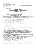
FIG. 1 Specimen Side Support Plates (Ref 4)
specimen. These plates are made of titanium carbide. A type of
side-support plate that has been used in compression jigs to
1800°F (982°C) is shown in Fig. 1(b) (4). This is an assembly
of small titanium carbide balls backed up by a titanium carbide
plate. The balls protrude through holes in the front retaining
plate. The holes for the balls are large enough to allow rotation
and translation of each ball while at the same time retaining the
balls in the plate assembly. The spacing of the balls, which is
normally about 1⁄8 in. (3.2 mm), determines the minimum
specimen thickness that can be tested without buckling between the balls. Rational values of the ball spacing can be
obtained from calculations based upon the plastic buckling of
simply supported plates where the plate width can be taken as
the ball spacing. Another type of jig has a number of leafspring supports on each side of the specimen (3, 5). This design
is limited to a temperature range in which the metal leaf-spring
elements can support the specimen satisfactorily. Jigs for use
with specimens that are heated by self resistance are discussed
in Ref 1, 6 and 7, which also provide quantitative information
on the effects of lubrication, lateral-support pressure, spring
constant, and misalignment.
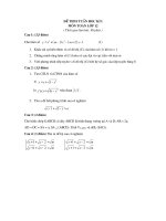
3.4.2 The side-support plates are assembled in a frame that
is part of the jig. A typical frame and jig assembly is shown in
Fig. 2. A furnace is placed around the jig after the specimen and
extensometer are assembled in the jig. The holes in the support
blocks are for auxiliary cartridge-type heaters.
3.4 Compression Testing Jigs—When testing sheet material,
buckling of the specimen during application of compessive
forces must be prevented. This may be accomplished by using
a jig containing side-support plates that bear against the faces
of the specimen. The jig must afford a suitable combination of
lateral-support pressure and spring constant to prevent buckling without interfering with axial deformation of the specimen
(1). Although suitable combinations vary somewhat with
variations in specimen material and thickness, testing
temperature, and accuracy of alignment, acceptable results can
be obtained with rather wide ranges of lateral-support pressure
and spring constant for any given test conditions. Generally,
the higher the spring constant of the jig, the lower the
lateral-support pressure that is required. Proper adjustment of
these test variables may be established in preliminary verification tests for the equipment (Section 9).
3.4.1 This practice does not intend to designate specific
compression jigs for testing sheet metals, but merely to provide
a few illustrations and references to jigs that have been used
successfully. Many other jigs are acceptable provided they
prevent buckling and pass the qualification tests set forth in
Section 9. Satisfactory results have been obtained in roomtemperature testing using the jigs illustrated in Test Methods
E9. These jigs usually require that the specimen be lubricated
to permit normal compression on loading. For elevatedtemperature testing, modified jigs that accommodate the heating and strain-measuring equipment as well as the temperaturesensing elements must be used. A number of compressiontesting jigs have been evaluated specifically for performance in
elevated-temperature tests (2, 3). The preferred type depends
on the material, its thickness, and the temperatures involved.
For moderately elevated temperatures, one of the roomtemperature designs may be used in an oven in which the air is
circulated to provide uniform heating. One design for sidesupport plates that has been found satisfactory for use at
temperatures up to 1000°F (538°C) when lubricated with
graphite is shown in Fig. 1(a) (4). Longitudinal grooves are cut
in each plate with the grooves offset across the thickness of the
4. Heating Apparatus
4.1 The apparatus and method for heating the specimens are
not specified, but in present practice the following are mainly
used.
4.1.1 The resistance of the specimen gage length to the
passage of an electric current,
4.1.2 Resistance heating supplemented by radiant heating,
4.1.3 Radiant heating,
4.1.4 Induction heating, or
4.1.5 Convection heating with circulating-air furnace.
4.2 The apparatus must be suitable for heating the specimen
under the conditions specified in Section 5.
5. Test Specimen
5.1 The size and shape of the test specimen should be based
on three requirements as follows:
2
E209 − 00 (2010)
5.2 The specimens are divided into two general classifications: those with rectangular cross sections and those with
round cross sections. The dimensions of the specimens are
optional. The specimen must be long enough to be compressed
to the required deformation without interference from a supporting jig but not long enough to permit buckling where it is
unsupported. The end allowance (dimension between the gage
points and the adjacent end of the uniform section) should be
a minimum of one half the width of rectangular specimens or
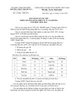
one half the diameter of round specimens. Typical acceptable
specimens are illustrated in Fig. 3 and Fig. 4.
5.3 When the dimensions of the test material permit, round
specimens should be used. Round specimens should be designed to be free from buckling up to the end point of the test
without lateral support. Rectangular specimens up to 0.250 in.
(6.35 mm) thick normally require lateral support; with greater
thicknesses lateral support may not be required in well-aligned
equipment. The methods covered by this specification are
normally satisfactory for testing sheet specimens down to
0.020 in. (0.51 mm) thick. With smaller thicknesses inaccuracies resulting from buckling and nonuniform straining tend to
increase; consequently, extra care in the design, construction,
and use of the test equipment is required to obtain valid results
for specimens in this thickness range. All compression specimens should be examined after they are tested; any evidence of
buckling invalidates the results for that specimen.
FIG. 2 Typical Compression Testing Jig for Sheet Specimens
Mounted on Support Jig (Ref 3)
5.4 The width and thickness of rectangular specimens and
diameter of round specimens at any point in the gage length
should not vary from the average by more than 0.001 in. (0.025
mm) for dimensions up to 1 in. (25.4 mm) or by more than 0.1
percent for dimensions above 1 in.
5.1.1 The specimen should be representative of the material
being investigated and should be taken from the material
produced in the form and condition in which it will be used,
5.1.2 The specimen should be adapted to meet the requirements on temperature control and rates of heating and
straining, and
5.1.3 The specimen should be conducive to the maintenance
of axial alignment uniform application of force, and freedom
from buckling when loaded to the end point in the apparatus
used.
5.5 The ends of end-loaded specimens should be parallel
within 0.00025 in. (0.0064 mm) for widths, thicknesses, and
diameters up to 1⁄2 in. (12.7 mm) and within 0.05 percent for
widths, thicknesses, and diameters above 1⁄2 in. The ends of
end-loaded specimens should be perpendicular to the sides
within 1⁄4 of a degree. All machined surfaces should have an
average surface finish of 63 µ in. or better. Rectangular
Dimensions
G.L.—Gage Length, in. (mm)
L—Uniform Section, in. (mm)
W—Width, in. (mm)
E.A.—End Allowance, in. (mm)
Specimen 1
Specimen 2
Specimen 3
1.000 ± 0.005
(25.4 ± 0.13)
2.500 ± 0.005
(63.5 ± 0.13)
0.625 ± 0.010
(15.9 ± 0.25)
0.75 (19)
2.000 ± 0.005
(50.8 ± 0.13)
3.000 ± 0.005
(76.2 ± 0.13)
1.000 ± 0.010
(25.4 ± 0.25)
0.50 (12.7)
2.000 ± 0.005
(50.8 ± 0.13)
2.50 min
(63.5)
0.500 ± 0.010
(12.7 ± 0.25)
0.25 min (6.35)
FIG. 3 Dimensions of Typical Rectangular Specimens
3
E209 − 00 (2010)
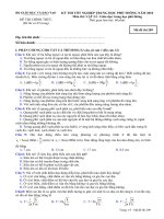
Dimensions
G.L.—Gage Length, in.
L—Uniform Section, in.
D—Diameter, in.
E.A.—End Allowance, in.
Specimen 1
Specimen 2
Specimen 3
1.000 ± 0.005
(25.4 ± 0.13)
1.500 ± 0.005
(38.1 ± 0.13)
0.500 ± 0.010
(12.7 ± 0.25)
0.25 (6.35)
2.000 ± 0.005
(50.8 ± 0.13)
3.375 ± 0.05
(85.8 ± 1.27)
1.125 ± 0.010
(28.6 ± 0.25)
0.69 (17.5)
1.000 ± 0.005
(25.4 ± 0.13)
1.500 ± 0.005
(38.1 ± 0.13)
0.375 ± 0.010
(9.5 ± 0.25)
0.25 (6.35)
NOTE 1—Specimen 3, because of its smaller diameter, is especially suitable for tests in which rapid heating is desired.
FIG. 4 Dimensions of Typical Round Specimens
both types of tests should be the same. The heating and holding
time actually used should be reported.
specimens should have a width of material, equal to at least the
thickness of the specimen, machined from all sheared or
stamped edges.
6.2 Rapid Heating—When a rapid heating rate is desired,
the preferred conditions for heating the gage length of the
specimen are as follows:
6.2.1 Sixty seconds or less to heat to the indicated nominal
test temperature, and
6.2.2 Holding time at the indicated nominal test temperature
before applying the force equal to the heating time.
6.2.3 The indicated control temperature of the specimen
should not vary more than 610°F (5.5°C) from the nominal
test temperature up to and including 1000°F (538°C) and not
more than 61.0 % of the nominal test temperature above
1000°F. The uniformity of temperature within the specimen
gage length should be within + 10°F and − 20°F (11°C) of the
nominal test temperature up to and including 1000°F and
within + 1.0 and − 2.0 % of the nominal test temperature above
1000°F.
5.6 Shouldered specimens may be used in lieu of specimens
with uniform width or diameter, provided the method of
applying force is consistent with requirements of axial
alignment, uniform application of force, and freedom from
buckling.
5.7 The surfaces of the rectangular specimens in contact
with the supporting jig should be lubricated to reduce friction.
The lubricant should have negligible reaction with the surface
of the specimen for the test temperature and time chosen and
should retain its lubricating properties for the duration of the
test. Molybdenum disulfide and graphite are examples of
lubricants that are used.
5.8 Specimen dimensions above 0.100 (2.54 mm) in. should
be measured to the nearest 0.001 in. (0.025 mm) or less;
dimensions under 0.100 in. should be measured to the nearest
1 percent or less. The average cross-sectional area of the gage
length should be used for calculation of stress.
NOTE 5—It is recognized that true temperatures will vary more than the
indicated temperatures. The permissible indicated temperature variations
specified in 6.1 and 6.2 are not to be construed as minimizing the
importance of good pyrometry practice and accurate temperature control
in these tests. All laboratories are obligated to keep both indicated and true
temperature variations as small as practicable. In view of the extreme
dependency of strength of materials on temperature, close temperature
control is necessary. The limits prescribed represent ranges that are
common practice. For further information on pyrometric practices reference should be made to the “Panel Discussion on Pyrometric Practices.” 4
6. Temperature Control
6.1 Conventional Heating—When a conventional-heating
rate is desired, variations in indicated temperature within the
gage length of the specimen should not exceed the following
limits during a test:
Test Temperature
Up to and including 1800°F (982°C)
Over 1800°F (982°C) up to and including
2800°F (1538°C)
Over 2800°F (1538°C) up to and including
3500°F (1927°C)
Over 3500°F (1927°C)
6.3 In rapid-heating tests a maximum overshoot in the
indicated temperature during the heating and holding period of
20°F or 2.0 % of the nominal test temperature, whichever is
greater, is allowed for a time not exceeding 30 s. The overshoot
limitation permits a larger temperature variation for a 30-s
period prior to testing than permitted for conventional-heating
tests, for which no overshoot in temperature beyond the
allowable variations in 6.1 is allowed.
Allowable
Variation, deg F
(deg C), plus
and minus
5 (3)
10 (5.5)
20 (11)
35 (19.5)
6.4 Conditions of heating to and holding at nominal test
temperature as specified in 6.1 through 6.3 are preferred to
The time of heating and holding prior to the start of the
stressing should be governed by the time necessary to ensure
that the temperatures can be maintained as specified. If
compression tests are being made as the counterpart to tension
test under Practice E21, the heating time and holding time in
4
Panel Discussion on Pyrometric Practices, ASTM STP 178, Am. Soc. Testing
Mats. (1955).
4
E209 − 00 (2010)
strain rate of 0.005 6 0.002 in./in. (0.5 6 0.2 percent)/min
from the start of loading to the end point of the test.
facilitate comparison of data between laboratories. The thermal
history given material during testing should be accurately
reported, particularly when equipment limitations or simulated
service testing cause deviations from the requirements of this
practice.
8.3 Rapid Strain Rate—When a rapid strain rate is desired
after conventional or rapid heating, use a strain rate of 0.5 6
0.2 in./in. (50 6 20 percent)/min from the start of loading to
the end point of the test. Since some ordinary test equipment is
not designed for rapid strain rates, precautions should be taken
to ensure that equipment used at rapid strain rates is accurate at
these rates.
6.5 The “indicated nominal temperature” and “indicated
temperatures” as used in the above paragraphs are temperatures
indicated by the temperature-measuring instrument with good
pyrometric practice.
8.4 When possible, use strain-pacing equipment, an automatic feed-back system, or other equivalent means to obtain a
constant strain rate. If such equipment is not available, maintain a constant crosshead speed to obtain the desired average
strain rate from the start of loading to the end point of the test.
The average strain rate can be determined from a time-intervalmarked force-strain record, a time-strain graph, or from a
stop-watch measurement of time from the start of loading to
the end point of the test. It should be recognized that the use of
machines with constant rate of crosshead movement does not
ensure constant strain rate throughout a test.
7. Temperature Measurement
7.1 Observe the following minimum precautions when thermocouples are used for temperature measurements:
7.1.1 Use small-diameter wires where heat conduction
along the couples might cause excessive heat loss as, for
example, where self-resistant heating is employed. In this
method 36-gage wire has been found satisfactory.
7.1.2 Keep the hot junction of the thermocouple in direct
contact with the test section of the specimen. In the case of
rapid-heating tests, fast response is required, and the preferred
method of attaching the thermocouples to the gage section is
capacitance welding. The proper power settings should be used
in order to minimize any undesirable metallurgical changes at
the attachment points.
7.1.3 Where radiant means of heating are used, shield the
thermocouple hot junction from direct radiation by the heating
elements in order to prevent erroneous high readings.
7.1.4 Where electrical self-resistance heating is used, exercise care to ensure that there is no superimposed voltage pickup
by the couples.
7.1.5 Use certified or otherwise calibrated thermocouple
wires for all tests. The calibration of a thermocouple may
change with age or after exposure to extreme temperatures.
Also, noble-metal thermocouples are easily contaminated.
Make frequent checks to ensure thermocouple accuracy. In the
case of base-metal thermocouples, clipping back the heated
portion is generally more convenient than recalibration.
8.5 The preferred rates of straining are those specified in 8.2
and 8.3 to facilitate comparison of data between laboratories. It
is further recommended that, when a faster rate of straining is
desired, the rate be 5.0 6 2.0 in./in. (500 6 200 percent)/min.
It is recommended that other rates of straining be confined to
those cases where special application of the data or material
properties requires intermediate rates. Report the strain rate
used with test results.
9. Strain Measurement
9.1 Record the stress-strain diagram up to the end point of
the test; prolonging the test beyond the end point defined in
Section 1 is optional.
9.2 Use an extensometer of Class B-2 or better as described
in Practice E83, Verification and Classification of Extensometers.4
NOTE 6—A discussion of the importance of strain-measuring systems
used with compression jigs is described in Ref. 2.
7.2 Methods other than thermocouples may be used for
measuring temperature provided it can be demonstrated that
they meet the requirements of Section 6. Temperature measurements with optical and radiation methods, for example,
must be corrected for deviations in specimen emissivity from
1.0 in determining the indicated specimen temperature.
9.3 Attach the extensometer directly to the gage length of
the specimen. No restrictions are placed on the method of
attachment except that it should not affect the properties, and
the extensometer should remain fixed to the gage length
without any slippage. Attachment of the extensometer to any
other part of the specimen or apparatus is not recommended,
but when such attachment is necessary, it must be accompanied
by proof that adequate corrections were used to compensate for
the strain that occurred outside the gage length, and the method
of attachment and location should be shown.
7.3 All equipment used for measuring , controlling and
recording tempertatures, should be verified and if necessary
calibrated against a standard periodically. Lead-wire error
should also be checked witht the load wires in place as they are
normally used.
9.4 The strain should be measured as opposite sides of the
specimen and averaged to give center-line strain.
8. Strain Rate During Test
8.1 Apply the force to the specimen to obtain uniform rates
of straining as specified in 8.2 and 8.3. Start the application of
the load at the end of the holding time at the specified test
temperature.
9.5 Verify the extensometer for sensitivity and accuracy in
accordance with Practice E83. The extensometer should fulfill
the requirements for the class of extensometer specified in 9.2
at room temperature. Pending the availability of standard
methods of calibration at elevated temperatures, exercise care
to be sure that the extensometer maintains calibration as the
8.2 Conventional Strain Rate—When a normal rate of
straining is desired after conventional or rapid heating, use a
5
E209 − 00 (2010)
10.4 The qualification procedure should be carried out on
the thinnest rectangular specimens or smallest diameter round
specimens to be tested in the system being qualified.
temperature of the specimen is increased to the test temperature
and during the test. This requires that those parts of the
extensometer that would be affected by the heat of the
specimen be shielded from temperature changes during the
test.
10.5 If the compression-test technique qualifies at room
temperature and at each test temperature in 400°F increments
to the maximum use temperature, it shall be considered
satisfactory for tests at any intermediate temperature in the
room-temperature to the maximum-use-temperature range,
provided that all conditions are maintained constant thereafter.
9.6 When rapid strain rates are used during a test, the
extensometer must be verified to have a rate of response
adequate to measure strain to the limits required in Section 7.
NOTE 7—The forces applied by the extensometer to the specimen may
introduce errors in the stress-strain data for small specimens or for tests at
very high temperatures where the strength of the specimens is low. In such
tests, counterbalancing or other mechanical arrangements should be used
to minimize the forces and bending moments introduced by the extensometer. The use of calculated corrections for the force of the extensometer is the least preferred method for correcting this type of error. For tests
where the load of the extensometer is significant, the report of the test
results should show the method of correction used.
11. Report
11.1 Report the following minimum information for each
test:
11.1.1 Indicated test temperature, heating rate, holding time
at test temperature, and strain rate, and
11.1.2 The 0.2 percent-offset compressive yield strength as
determined from the stress-strain curve.
10. Qualification of Test Apparatus
11.2 Report the following additional information when
needed for design or other purposes:
11.2.1 Compressive modulus of elasticity,
11.2.2 Compressive yield strength at other amounts of offset
up to the end point of the test,
11.2.3 Copy of stress-strain curve,
11.2.4 Drop-of-beam yield point if such a yield point
occurs,
11.2.5 Tangent modulus as a function of stress, and
11.2.6 Secant modulus as a function of stress.
10.1 The complete compression-test system consisting of
jig, strain instrument, and recorders should be qualified, in
accordance with 10.2 – 10.5, by each of the personnel assigned
to conduct test programs.
10.2 At room temperature, conduct tests to the proportional
limit on five different specimens of 2024-T3 aluminum alloy to
establish the elastic modulus during both the application and
removal of forces. If each of the modulus values so determined
falls within 10.7 × 10⁶ psi (7.38 × 10⁴ MPa) 65 percent, the
compression-testing technique qualifies for room-temperature
operation.
11.3 The following information essential to the interpretation of the results should also be given:
11.3.1 Description of the material tested and the orientation
of the specimen with respect to the test material,
11.3.2 Nominal size and type of specimen used including
machining methods and any special techniques to control
surface finish,
11.3.3 Type of test apparatus and method of heating, and
11.3.4 Accuracy of apparatus.
10.3 At elevated temperatures starting at 400°F (204°C) and
in 400°F (220°C) increments to the maximum use temperature,
determine the modulus of elasticity in tension for three
specimens at each temperature both loading and unloading
using an alloy with distinct elastic properties at each temperature. Conduct identical tests in compression using the compression test technique. If the compression moduli from consecutive specimens fall within 65 % of the average tension
modulus, the technique qualifies for operation to the maximum
temperature successfully reached in this procedure.
11.4 Any deviations from the preferred or specified conditions of testing should be indicated with the results of the tests.
REFERENCES
(1) Bernett, E. C., and Gerberich, W. W., “Rapid-Rate Compression
Testing of Sheet Materials at High Temperatures,” ASTM STP 303,
ASTTA, Am. Soc. Testing Mats., 1961, pp. 33–46.
(2) Gerard, George, “An Evaluation of Compression-Testing Techniques
of Sheet Materials at Elevated Temperatures,” ASTM STP 303,
ASTTA, Am. Soc. Testing Mats., 1961, pp. 3–11.
(3) Hyler, W. S., “An Evaluation of Compression-Testing Techniques for
Determining Elevated-Temperature Properties of Titanium Sheet,”
Titanium Metallurgical Laboratory Report No. 43, June 8, 1956.
(4) King, J. P., “Compression Testing at Elevated Temperatures,” Metals
Engineering Quarterly, MENQA, Vol 1, No. 3, August, 1961, pp.
30–38.
(5) Breindel, W. W., Carlson, R. L., and Holden, F. C., “An Evaluation of
a System for the Compression Testing of Sheet Materials at Elevated
Temperatures,” ASTM STP 303, ASTTA, Am. Soc. Testing Mats.,
1961, pp. 77–84.
(6) Fenn, Jr., R. W., “Compression Testing Sheet Magnesium Utilizing
Rapid Heating,” Proceedings, ASTEA, Am. Soc. Testing Mats., Vol
60, 1960, p. 940.
(7) Fenn, Jr., R. W., “Evaluation of Test Variables in the Determination of
Elevated-Temperature Compressive Yield Strength of Magnesium
Alloy Sheet,” ASTM STP 303, ASTTA, Am. Soc. Testing Mats., 1961,
pp. 48–59.
6
E209 − 00 (2010)
ASTM International takes no position respecting the validity of any patent rights asserted in connection with any item mentioned
in this standard. Users of this standard are expressly advised that determination of the validity of any such patent rights, and the risk
of infringement of such rights, are entirely their own responsibility.
This standard is subject to revision at any time by the responsible technical committee and must be reviewed every five years and
if not revised, either reapproved or withdrawn. Your comments are invited either for revision of this standard or for additional standards
and should be addressed to ASTM International Headquarters. Your comments will receive careful consideration at a meeting of the
responsible technical committee, which you may attend. If you feel that your comments have not received a fair hearing you should
make your views known to the ASTM Committee on Standards, at the address shown below.
This standard is copyrighted by ASTM International, 100 Barr Harbor Drive, PO Box C700, West Conshohocken, PA 19428-2959,
United States. Individual reprints (single or multiple copies) of this standard may be obtained by contacting ASTM at the above
address or at 610-832-9585 (phone), 610-832-9555 (fax), or (e-mail); or through the ASTM website
(www.astm.org). Permission rights to photocopy the standard may also be secured from the Copyright Clearance Center, 222
Rosewood Drive, Danvers, MA 01923, Tel: (978) 646-2600; />
7