E 331 00 (2016)
Bạn đang xem bản rút gọn của tài liệu. Xem và tải ngay bản đầy đủ của tài liệu tại đây (171.97 KB, 5 trang )
Designation: E331 − 00 (Reapproved 2016)
Standard Test Method for
Water Penetration of Exterior Windows, Skylights, Doors,
and Curtain Walls by Uniform Static Air Pressure
Difference1
This standard is issued under the fixed designation E331; the number immediately following the designation indicates the year of
original adoption or, in the case of revision, the year of last revision. A number in parentheses indicates the year of last reapproval. A
superscript epsilon (´) indicates an editorial change since the last revision or reapproval.
This standard has been approved for use by agencies of the U.S. Department of Defense.
2. Referenced Documents
1. Scope
2.1 ASTM Standards:2
E631 Terminology of Building Constructions
1.1 This test method covers the determination of the resistance of exterior windows, curtain walls, skylights, and doors
to water penetration when water is applied to the outdoor face
and exposed edges simultaneously with a uniform static air
pressure at the outdoor face higher than the pressure at the
indoor face.
3. Terminology
3.1 Definitions—For definitions of general terms relating to
building construction used in this test method, see Terminology
E631.
3.2 Definitions of Terms Specific to This Standard:
3.2.1 specimen, n—the entire assembled unit submitted for
test as described in Section 8.
1.2 This test method is applicable to any curtain-wall area or
to windows, skylights, or doors alone.
1.3 This test method addresses water penetration through a
manufactured assembly. Water that penetrates the assembly,
but does not result in a failure as defined herein, may have
adverse effects on the performance of contained materials such
as sealants and insulating or laminated glass. This test method
does not address these issues.
3.2.2 test pressure difference, n—the specified difference in
static air pressure across the closed and locked or fixed
specimen expressed as Pascals (lbf/ft2).
3.2.3 water penetration, n—penetration of water beyond a
plane parallel to the glazing (the vertical plane) intersecting the
innermost projection of the test specimen, not including
interior trim and hardware, under the specified conditions of air
pressure difference across the specimen. For products with
non-planer glazing surfaces (domes, vaults, pyramids, etc.), the
plane defining water penetration is the plane defined by the
innermost edges of the unit frame.
1.4 The proper use of this test method requires a knowledge
of the principles of pressure measurement.
1.5 The values stated in SI units are to be regarded as the
standard. The values given in parentheses are mathematical
conversions to inch-pound units that are provided for information only and are not considered standard.
1.6 This standard does not purport to address all of the
safety concerns, if any, associated with its use. It is the
responsibility of the user of this standard to establish appropriate safety and health practices and determine the applicability of regulatory limitations prior to use. For specific hazard
statements, see 7.1.
4. Summary of Test Method
4.1 This test method consists of sealing the test specimen
into or against one face of a test chamber, supplying air to or
exhausting air from the chamber at the rate required to
maintain the test pressure difference across the specimen, while
spraying water onto the outdoor face of the specimen at the
required rate and observing any water penetration.
1
This test method is under the jurisdiction of ASTM Committee E06 on
Performance of Buildings and is the direct responsibility of Subcommittee E06.51
on Performance of Windows, Doors, Skylights and Curtain Walls.
Current edition approved Aug. 1, 2016. Published August 2016. Originally
approved in 1967. Last previous edition approved in 2009 as E331 – 00(2009). DOI:
10.1520/E0331-00R16.
2
For referenced ASTM standards, visit the ASTM website, www.astm.org, or
contact ASTM Customer Service at For Annual Book of ASTM
Standards volume information, refer to the standard’s Document Summary page on
the ASTM website.
Copyright © ASTM International, 100 Barr Harbor Drive, PO Box C700, West Conshohocken, PA 19428-2959. United States
1
E331 − 00 (2016)
5. Significance and Use
6. Apparatus
5.1 This test method is a standard procedure for determining
the resistance to water penetration under uniform static air
pressure differences. The air-pressure differences acting across
a building envelope vary greatly. These factors should be fully
considered prior to specifying the test pressure difference to be
used.
6.1 The description of apparatus in this section is general in
nature and any arrangement of equipment capable of performing the test procedure within the allowable tolerances is
permitted.
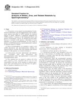
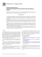
6.2 Major Components (Fig. 1):
6.2.1 Test Chamber—A test chamber or box with an
opening, a removable mounting panel, or one open side in
which or against which the specimen is installed and sealed. At
least one static pressure tap shall be provided to measure the
chamber pressure, and shall be so located that the reading is
unaffected by the velocity of the air supply to or from the
chamber. The air supply opening into the chamber shall be
arranged so that the air does not impinge directly on the test
specimen with any significant velocity. A means of access into
the chamber may be provided to facilitate adjustments and
observations after the specimen has been installed.
NOTE 1—In applying the results of tests by this test method, note that
the performance of a wall or its components, or both, may be a function
of proper installation and adjustment. In service, the performance will also
depend on the rigidity of supporting construction and on the resistance of
components to deterioration by various causes, vibration, thermal expansion and contraction, etc. It is difficult to simulate the identical complex
wetting conditions that can be encountered in service, with large windblown water drops, increasing water drop impact pressures with increasing wind velocity, and lateral or upward moving air and water. Some
designs are more sensitive than others to this upward moving water.
NOTE 2—This test method does not identify unobservable liquid water
which may penetrate into the test specimen.
NOTE 1—For a negative pressure system, the water-spray grid would be located outside the chamber and the air supply would be replaced by an
air-exhaust system.
FIG. 1 General Arrangement of the Water Leakage Apparatus Positive Chamber System
2
E331 − 00 (2016)
6.2.2 Air System—A controllable blower, compressed air
supply, exhaust system, or reversible blower designed to
provide the required maximum air-pressure difference across
the specimen. The system must provide essentially constant
airflow at a fixed pressure for the required test period.
6.2.3 Pressure-Measuring Apparatus—A device to measure
the test pressure difference within a tolerance of 62 % or
62.5 Pa (60.01 in. of water column), whichever is greater.
6.2.4 Water-Spray System—The water-spray system shall
deliver water uniformly against the exterior surface of the test
specimen at a minimum rate of 3.4 L ⁄m2 · min
(5.0 U.S. gal ⁄ft2 · h).
6.2.4.1 The water-spray system shall have nozzles spaced
on a uniform grid, located at a uniform distance from the test
specimen, and shall be adjustable to provide the specified
quantity of water in such a manner as to wet all of the test
specimen uniformly and to wet those areas vulnerable to water
penetration. If additional nozzles are required to provide
uniformity of water spray at the edge of the test specimen, they
shall be equally spaced around the entire spray grid.
horizontal joint accommodating vertical expansion, such joint
being at or near the bottom of the specimen, and all connections at the top and bottom of the units.
8.1.1 All parts of the test specimen shall be full size, using
the same materials, details, and methods of construction and
anchorage as used on the actual building.
8.1.2 Conditions of structural support shall be simulated as
accurately as possible.
8.2 Window, skylight, door, or other component test specimens shall consist of the entire assembled unit, including frame
and anchorage as supplied by the manufacturer for installation
in the building.
8.2.1 If only one specimen is to be tested, the selection shall
be determined by the specifying authority.
NOTE 3—It should be recognized, especially with windows, that
performance is likely to be a function of size and geometry. Therefore,
select specimens covering the range of sizes to be used in a building. In
general, the largest size of a particular design, type, construction, and
configuration to be used should be tested.
9. Calibration
7. Hazards
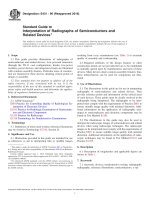
9.1 The ability of the test apparatus to meet the requirements of 6.2.4 shall be checked by using a catch box, the open
face of which shall be located at the position of the face of the
test specimen. The calibration device is illustrated in Fig. 2.
The catch box shall be designed to receive only water
impinging on the plane of the test specimen face and to exclude
all run-off water from above. The box shall be 610 mm (24 in.)
square, divided into four areas each 305 mm (12 in.) square.
Use a cover approximately 760 mm (30 in.) square to prevent
water from entering the calibration box before and after the
timed observation interval. The water impinging on each area
shall be captured separately. A spray that provides at least
1.26 L ⁄min (20 gal ⁄h) total for the four areas and not less than
0.25 L ⁄min (4 gal/h) nor more than 0.63 L ⁄min (10 gal ⁄h) in
any one square shall be acceptable.
9.1.1 The water-spray system shall be calibrated at both
upper corners and at the quarter point of the horizontal center
line (of the spray system). If a number of identical, contiguous,
7.1 Warning—Glass breakage will not normally occur at
the small pressure differences applied in this test. Excessive
pressure differences may occur, however, due to error in
operation or when the apparatus is used for other purposes such
as structural testing; therefore, exercise adequate precautions to
protect personnel.
8. Test Specimen
8.1 Test specimens shall be of sufficient size to determine
the performance of all typical parts of the fenestration system.
For curtain walls or walls constructed with prefabricated units,
the specimen width shall be not less than two typical units plus
the connections and supporting elements at both sides, and
sufficient to provide full loading on at least one typical vertical
joint or framing member or both. The height shall be not less
than the full building-story height or the height of the unit,
whichever is greater, and shall include at least one full
FIG. 2 Catch Box for Calibrating Water-Spray System
3
E331 − 00 (2016)
11.7 Observe and record the points of water penetration, if
any.
modular spray systems are used, only one module need be
calibrated. The system shall be calibrated with the catch boxes
at a distance within 650 mm (2 in.) of the test specimen
location from the nozzle. The reference point for location of the
spray system from the specimen shall be measured from the
exterior glazing surface of the specimen farthest from the spray
system nozzles. The water spray shall be installed parallel to
the plane of the specimen. Recalibrate at intervals of not more
than six months.
12. Report
12.1 Report the following information:
12.1.1 Date of test and date of report.
12.1.2 Identification of the specimen (manufacturer, source
of supply, dimensions, model, type, materials, and other
pertinent information).
12.1.3 Detailed drawings of the specimen that provide a
description of the physical characteristics including dimensioned section profiles, sash or door dimensions and
arrangement, framing location, panel arrangement, installation
and spacing of anchorage, weatherstripping, locking
arrangement, hardware, sealants, glazing details, angle from
the horizontal for skylights, and any other pertinent construction details. Any modifications made on the specimen to obtain
the reported values shall be noted on the drawings.
12.1.4 For window, skylight, and door components, a description of the locking and operating mechanism.
12.1.5 Identification of glass thickness and type and method
of glazing.
12.1.6 Type or types of weatherstrip.
12.1.7 A statement or tabulation of pressure difference or
differences exerted across the specimen and temperature during
the tests and water application rates during the test.
12.1.8 A record of all points of water penetration on the
indoor face of the test specimen, and of water penetration as
defined in 3.2.3.
12.1.9 When the tests are made to check the conformity of
the specimen to a particular specification, an identification or
description of that specification shall be included.
12.1.10 A statement that the test or tests were conducted in
accordance with this test method, or a complete description of
any deviations from this test method.
10. Information Required
10.1 The test-pressure difference or differences at which
water penetration is to be determined, unless otherwise
specified, shall be 137 Pa (2.86 lbf ⁄ft2).
10.2 Unless otherwise specified, failure criteria of this test
method shall be defined as water penetration in accordance
with 3.2.3. Failure also occurs whenever water penetrates
through the perimeter frame of the test specimen. Water
contained within drained flashing, gutters, and sills is not
considered failure.
11. Procedure
11.1 Remove any sealing material or construction that is not
normally a part of the assembly as installed in or on a building.
Fit the specimen into or against the chamber opening with the
outdoor side of the specimen facing both the high pressure side
of the chamber and the water spray, and in such a manner, that
no joints or openings are obstructed. Skylight specimens shall
be tested at the minimum angle from the horizontal for which
they are designed to be installed. Seal the outer perimeter of the
specimen to the chamber wall and seal at no other points.
NOTE 4—Nonhardening mastic compounds or pressure-sensitive tape
can be used effectively to seal the test specimen to the chamber opening,
to seal the access door to the chamber, and to achieve airtightness in the
construction of the chamber. These materials can be used to seal a separate
mounting panel to the chamber. Rubber gaskets with clamping devices
may also be used for this purpose provided that the gasket is highly
flexible and has a small contact edge.
12.2 If several identical specimens of a component are
tested, the results for all specimens shall be reported, each
specimen being properly identified, particularly with respect to
distinguishing features or differing adjustments. A separate
drawing for each specimen shall not be required if all differences between them are noted on the drawings provided.
11.2 Without disturbing the seal between the specimen and
the test chamber, adjust all operable units included in the test
specimen so that their operation conforms to the specification
requirements. Adjust all hardware for maximum tightness
without interfering with their operation.
13. Precision and Bias
11.3 Submit each operable unit to five cycles of opening,
closing, and locking prior to testing.
13.1 No statement is made either on the precision or bias of
this test method for measuring water penetration since the
result merely states whether there is conformance to the criteria
specified for success.
11.4 Adjust the water spray to the specified rate.
11.5 Apply the air-pressure difference within 15 s and
maintain this pressure, along with the specified rate of water
spray, for 15 min.
14. Keywords
14.1 curtain walls; doors; skylights; water penetration; windows
11.6 Remove the air-pressure difference and stop the water
spray.
4
E331 − 00 (2016)
ASTM International takes no position respecting the validity of any patent rights asserted in connection with any item mentioned
in this standard. Users of this standard are expressly advised that determination of the validity of any such patent rights, and the risk
of infringement of such rights, are entirely their own responsibility.
This standard is subject to revision at any time by the responsible technical committee and must be reviewed every five years and
if not revised, either reapproved or withdrawn. Your comments are invited either for revision of this standard or for additional standards
and should be addressed to ASTM International Headquarters. Your comments will receive careful consideration at a meeting of the
responsible technical committee, which you may attend. If you feel that your comments have not received a fair hearing you should
make your views known to the ASTM Committee on Standards, at the address shown below.
This standard is copyrighted by ASTM International, 100 Barr Harbor Drive, PO Box C700, West Conshohocken, PA 19428-2959,
United States. Individual reprints (single or multiple copies) of this standard may be obtained by contacting ASTM at the above
address or at 610-832-9585 (phone), 610-832-9555 (fax), or (e-mail); or through the ASTM website
(www.astm.org). Permission rights to photocopy the standard may also be secured from the Copyright Clearance Center, 222
Rosewood Drive, Danvers, MA 01923, Tel: (978) 646-2600; />
5