Astm f 2896 11
Bạn đang xem bản rút gọn của tài liệu. Xem và tải ngay bản đầy đủ của tài liệu tại đây (182.42 KB, 9 trang )
Designation: F2896 − 11
An American National Standard
Standard Specification for
Reinforced Polyethylene Composite Pipe For The Transport
Of Oil And Gas And Hazardous Liquids1
This standard is issued under the fixed designation F2896; the number immediately following the designation indicates the year of
original adoption or, in the case of revision, the year of last revision. A number in parentheses indicates the year of last reapproval. A
superscript epsilon (´) indicates an editorial change since the last revision or reapproval.
with Required Notch Toughness
A519 Specification for Seamless Carbon and Alloy Steel
Mechanical Tubing
D624 Test Method for Tear Strength of Conventional Vulcanized Rubber and Thermoplastic Elastomers
D638 Test Method for Tensile Properties of Plastics
D792 Test Methods for Density and Specific Gravity (Relative Density) of Plastics by Displacement
D1000 Test Methods for Pressure-Sensitive AdhesiveCoated Tapes Used for Electrical and Electronic Applications
D1598 Test Method for Time-to-Failure of Plastic Pipe
Under Constant Internal Pressure
D1599 Test Method for Resistance to Short-Time Hydraulic
Pressure of Plastic Pipe, Tubing, and Fittings
D1600 Terminology for Abbreviated Terms Relating to Plastics
D1693 Test Method for Environmental Stress-Cracking of
Ethylene Plastics
D2122 Test Method for Determining Dimensions of Thermoplastic Pipe and Fittings
D2256/D2256M Test Method for Tensile Properties of Yarns
by the Single-Strand Method
D2513 Specification for Polyethylene (PE) Gas Pressure
Pipe, Tubing, and Fittings
D2774 Practice for Underground Installation of Thermoplastic Pressure Piping
D2837 Test Method for Obtaining Hydrostatic Design Basis
for Thermoplastic Pipe Materials or Pressure Design Basis
for Thermoplastic Pipe Products
D2992 Practice for Obtaining Hydrostatic or Pressure Design Basis for “Fiberglass” (Glass-Fiber-Reinforced
Thermosetting-Resin) Pipe and Fittings
D3850 Test Method for Rapid Thermal Degradation of Solid
Electrical Insulating Materials By Thermogravimetric
Method (TGA)
D5035 Test Method for Breaking Force and Elongation of
Textile Fabrics (Strip Method)
F412 Terminology Relating to Plastic Piping Systems
F585 Guide for Insertion of Flexible Polyethylene Pipe Into
Existing Sewers
1. Scope
1.1 This specification covers requirements and test methods
for materials, dimensions, workmanship, and markings for
on-site manufactured multilayer reinforced polyethylene composite pipe. It covers nominal sizes 6 in. through 36 in. (150
mm through 915 mm). These multilayered reinforced polyethylene composite pipe products2 are assembled and installed in
various lengths, including long continuous lengths. These
products are intended for the transport of crude oil, natural gas
and hazardous liquids in the rehabilitation of existing pipelines
and for new pipelines.
NOTE 1—Hazardous liquids are those liquids defined by the U.S.
Department of Transportation in 49 CFR 195.2.
1.2 The values stated in inch-pound units are to be regarded
as standard. The values given in parentheses are mathematical
conversions to SI units that are provided for information only
and are not considered standard.
1.3 This standard does not purport to address all of the
safety concerns, if any, associated with its use. It is the
responsibility of the user of this standard to establish appropriate safety and health practices and determine the applicability of regulatory limitations prior to use.
2. Referenced Documents
2.1 ASTM Standards:3
A312/A312M Specification for Seamless, Welded, and
Heavily Cold Worked Austenitic Stainless Steel Pipes
A333/A333M Specification for Seamless and Welded Steel
Pipe for Low-Temperature Service and Other Applications
1
This specification is under the jurisdiction of ASTM Committee F17 on Plastic
Piping Systems and is the direct responsibility of Subcommittee F17.11 on
Composite.
Current edition approved Nov. 15, 2011. Published December 2011. DOI:
10.1520/F2896–11.
2
The reinforced polyethylene composite pipe product described in this standard
is covered by patents. Interested parties are invited to submit information regarding
the identification of an alternative(s) to this patented item to the ASTM International
Headquarters. Your comments will receive careful consideration at a meeting of the
responsible technical committee, which you may attend.
3
For referenced ASTM standards, visit the ASTM website, www.astm.org, or
contact ASTM Customer Service at For Annual Book of ASTM
Standards volume information, refer to the standard’s Document Summary page on
the ASTM website.
Copyright © ASTM International, 100 Barr Harbor Drive, PO Box C700, West Conshohocken, PA 19428-2959. United States
1
F2896 − 11
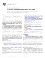
FIG. 1 Typical Construction of Reinforced Polyethylene Composite Pipe
(HDB), Hydrostatic Design Stress (HDS), Pressure Design Basis (PDB), Strength Design Basis (SDB), and
Minimum Required Strength (MRS) Ratings for Thermoplastic Piping Materials or Pipe5
2.5 Other Documents:7
49 CFR 195 Code of Federal Regulations - Transportation of
Hazardous Liquids by Pipeline
F1249 Test Method for Water Vapor Transmission Rate
Through Plastic Film and Sheeting Using a Modulated
Infrared Sensor
F1606 Practice for Rehabilitation of Existing Sewers and
Conduits with Deformed Polyethylene (PE) Liner
F1668 Guide for Construction Procedures for Buried Plastic
Pipe
F2619/F2619M Specification for High-Density Polyethylene
(PE) Line Pipe
F2620 Practice for Heat Fusion Joining of Polyethylene Pipe
and Fittings
G14 Test Method for Impact Resistance of Pipeline Coatings
(Falling Weight Test)
2.2 ANSI Standards:4
B 16.5 Pipe, Flanges, and Flanged Fittings
2.3 API Standards:5
17 J Unbonded Flexible Pipe – Unbonded Flexible Pipe
2.4 PPI Standards:6
TR-3/2010 HDB/HDS/PDB/SDB/MRS Policies – Policies
and Procedures for Developing Hydrostatic Design Basis
3. Terminology
3.1 Definitions are in accordance with Terminology F412
and abbreviations are accordance with Terminology D1600,
unless otherwise specified.
3.2 Definitions of Terms Specific to This Standard:
3.2.1 Reinforced Polyethylene Composite Pipe (RPCP),
n—Polyethylene piping helically wrapped with non-metallic
reinforcing materials and then overwrapped with an outer
protective layer (Fig. 1).
3.2.2 core pipe, n—the inner liner or polyethylene pipe
3.2.2.1 Discussion—The typical reinforced polyethylene
composite pipe to be described in this standard is a multilayer
pipe construction consisting of a polyethylene liner or core
pipe, co-helically wrapped with multiple layers (counter
4
Available from Available from American National Standards Institute (ANSI),
25 W. 43rd St., 4th Floor, New York, NY 10036, .
5
Available from American Petroleum Institute (API), 1220 L. St., NW,
Washington, DC 20005-4070, .
6
Available from Plastics Pipe Institute (PPI), 105 Decker Court, Suite 825,
Irving, TX 75062, .
7
Available online from the Department of Transportation at http://
setonresourcecenter.com/transportation/49CFR/172_101tb.pdf
2
F2896 − 11
TABLE 1 Physical Properties of Polyamide Reinforcing Fibers
Fiber Properties
Specific Density
Tensile Strength at Break
Elongation at Break
Specific Tensile Strength
Decomposition Temperature
Test Method
D792
D2256/D2256M
D2256/D2256M
D2256/D2256M
D3850
Units
lb/in3 (g/cm3)
psi
%
in. (cm)
°F (°C)
Minimum Value
0.052 (1.44)
424,000 (2921)
2.4
815,000 (2,070,100)
800 (427)
Polyester fibers used in the polyester pulling tapes shall have
the minimum properties as shown in Table 5. Polyester tapes
shall have the minimum properties as shown in Table 6.
5.3.2 Polyamide fibers—Polyamide fibers used in the polyamide pulling tapes shall have the minimum properties as
shown in Table 1. Polyamide tapes shall have the minimum
properties as shown in Table 2.
wound in pairs) (of non-metallic reinforcing material, and then
wrapped with an outer polyethylene or other thermoplastic
protective layer. The polyethylene core pipe is heat fusion
joined to make long continuous lengths of pipe. Longitudinal
direction reinforcing materials may be applied to reinforce the
pipe linearly to increase the strength in sliplining installations.
The polyethylene liner pipe may either be manufactured on-site
or shipped to the site and fusion joined on-site prior to being
wrapped with the reinforcing materials. These products are
constructed from individual pipe lengths of the polyethylene
core pipe and not from coiled polyethylene pipe. See Fig. 1.
3.2.3 on-site, adj—accomplished or located at the site of a
particular activity or concern.
3.2.4 pressure class, n—The maximum allowable operating
pressure.
NOTE 3—Non-structural reinforcing pulling tapes provide increased
longitudinal strength during installation, including sliplining installations.
5.4 External protective coating materials:
5.4.1 Polyethylene tape— Polyethylene coating materials
used in the assembly of the Reinforced Polyethylene Composite Pipe shall have the minimum properties as shown in Table
8.
5.4.2 Polyethylene/Butyl rubber tape—Polyethylene/Butyl
rubber coating materials used in the assembly of the Reinforced Polyethylene Composite Pipe shall have the minimum
properties as shown in Table 9.
4. Ordering Information
4.1 General—The reinforced polyethylene multilayer composite pipe meeting the requirements of this specification are
classified by pressure design basis.
5.5 Rework materials—Excluding the core pipe, reground
or reprocessed polyethylene or other thermoplastic materials
are not permitted to be used. Reinforcing materials shall not be
recovered and reused.
NOTE 2—Fig. 1 is meant to be representative of the reinforced
polyethylene PE composite pipes described in this standard.
5.6 Steel End Connections—Steel materials in end connections shall meet the requirements of Specifications A312/
A312M, A333/A333M or A519. Specialty steel grades requested by the purchaser must meet the same minimum
performance requirements.
5. Materials
5.1 Polyethylene Pipe Materials :
5.1.1 Polyethylene—Polyethylene shall be PE4710 pipe in
accordance with Specification F2619/F2619M or Specification
D2513.
6. Requirements
5.2 Reinforcement Materials:
5.2.1 Polyamide reinforcing fibers—Polyamide reinforcing
fibers used in the assembly of the Reinforced Polyethylene
Composite Pipe shall have the minimum properties as shown in
Table 1. Polyamide reinforcing fabrics shall have the minimum
properties as shown in Table 2.
5.2.2 Ultra high molecular weight polyethylene (UHMW)
reinforcing fibers—Polyethylene reinforcing fibers used in the
assembly of the Reinforced Polyethylene Composite Pipe shall
have the minimum properties as shown in Table 3. UHMW
Polyethylene reinforcing fabrics shall have the minimum
properties as shown in Table 4.
5.2.3 Polyester fibers—Polyester reinforcing fibers used in
the assembly of the Reinforced Polyethylene Composite Pipe
shall have the minimum properties as shown in Table 5.
Polyester reinforcing fabrics shall have the minimum properties as shown in Table 6.
6.1 Workmanship—The polyethylene core pipe shall be
inspected for defects and damage prior to wrapping with the
reinforcing materials. The reinforcing layers shall be applied
uniformly and be free from irregularities and visible defects. If
defects or damages are found the material is to be rejected.
6.2 Core Pipe Dimensions—Polyethylene core pipe shall
comply with the requirements listed in Specification F2619/
F2619M or Specification D2513.
6.3 Fabric Wrap—The fabric wrap shall be overlapped and
the fabric wrap angle is the natural wrap angle of 55°. The
fabric warp angle shall be calibrated and controlled to within a
tolerance of 6 2 degrees of the design wrap angle. The fabric
wrap angle shall be measured and confirmed to 6 2 degrees of
the design wrap angle every 300 feet (100m).
6.4 Multilayer Pipe Dimensions—Pipe Dimensions shall
comply with Table 10 and Table 11, when measured in
accordance with Test Method D2122.
5.3 Non-Structural Materials:
5.3.1 Polyester fibers—Polyester non-structural fibers used
in the assembly of the Reinforced Polyethylene Composite
Pipe shall have the minimum properties as shown in Table 7.
NOTE 4—As these piping products are generally assembled on site, the
conditioning requirements that are specified in Test Method D2122
3
F2896 − 11
TABLE 2 Physical Properties of Polyamide Reinforcing Fabrics
Fiber Properties
Tensile Strength at Break
Test Method
D5035
Units
Lbs/inch (N/cm)
Minimum Value
2,500 (4380)
TABLE 3 Physical Properties of UHMW Polyethylene Reinforcing Fibers
Fiber Properties
Specific Density
Tensile Strength at Break
Elongation at Break
Decomposition Temperature
Test Method
D792
D2256/D2256M
D2256/D2256M
D3850
Units
lb/in3 (g/cm3)
psi
%
°F (°C)
Minimum Value
0.035 (0.97)
316,000 (2177)
2.9
300 (149)
TABLE 4 Physical Properties of UHMW Polyethylene Reinforcing Fabrics
Fiber Properties
Tensile Strength at Break
Units
D5035
Test Method
Lbs/inch (N/cm)
Minimum Value
2,500 (4380)
TABLE 5 Physical Properties of Polyester Reinforcing Fibers
Property
Specific Density
Tensile Strength at Break
Elongation at Break
Test Method
D792
D2256/D2256M
D2256/D2256M
Units
lb/in3 (g/cm3)
psi
%
Minimum Value
0.051 (1.41)
400,000 (2756)
3.8
TABLE 6 Physical Properties of Polyester Reinforcing Fabrics
Fiber Properties
Tensile Strength at Break
Test Method
D5035
Units
Lbs/inch (N/cm)
Minimum Value
2,500 (4380)
TABLE 7 Physical Properties of Polyester Non-Reinforcing Fibers
Property
Specific Density
Breakload (1000 denier fiber)
Elongation at Break
Test Method
D792
D2256/D2256M
D2256/D2256M
Units
lb/in3 (g/cm3)
g/denier
%
Minimum Value
0.051 (1.41)
8.6
10.6
TABLE 8 Physical Properties of Polyethylene protective tape
Tape Properties
Tensile Strength at Break
Elongation at Break
Impact Resistance
Water Vapor Transmission Rate, (100°F,
100% RH)
Water Vapor Transmission Rate, (100°F,
100% RH)
Test Method
D1000
D1000
G14
F1249
Units
lbs/in
%
in-lbs (Nm)
g/in2/24hr,
Minimum Value
25
20
45 (5.0)
0.03
F1249
g/m2
0.5
TABLE 9 Physical Properties of polyethylene/butyl rubber protective tape
Tape Properties
Tensile Strength at Break
Tear Strength
Elongation at Break
Environmental Stress Crack Resistance
Test Method
D638
D624
D638
D1693, Condition C
Units
lb/in2, (kg/cm2)
lb/in, (kg/cm)
%
Hrs
Minimum Value
1320 (92.8)
300 (53.7)
20
>500, no cracking
those temperatures shall be provided based on Test Method
D2837 analysis or by interpolation using higher temperature
PDB values as described in PPI TR-3/2010. The PDB shall be
established for a minimum of one diameter of composite pipe
in each of the diameter ranges as follows; 6 to 16 inch, >16 to
24 inch, and >24 to 36 inch. The pressure design basis of other
pipe sizes within the same pressure class having the same
obviously cannot be applied. Other than conditioning, the measurement
requirements of Test Method D2122 are to be followed in measuring the
pipe dimensions.
6.5 Pressure Design Basis (PDB)—: The multilayer reinforced polyethylene composite pipe shall have an established
pressure design basis at 73°F (23°C) as listed in Table 10 and
Table 11 and as per the requirements of Test Method D2837.
For higher temperature service applications, PDB values for
4
F2896 − 11
TABLE 10 Dimensions for Pressure Class 750 psi (5.17 MPa) Pipe
Nominal Pipe Size
6
8
10
12
14
16
18
20
22
24
26
28
30
32
34
36
PDB, psi (MPa)
2000 (13.79)
2000 (13.79)
2000 (13.79)
2000 (13.79)
2000 (13.79)
2000 (13.79)
2000 (13.79)
2000 (13.79)
2000 (13.79)
2000 (13.79)
2000 (13.79)
2000 (13.79)
2000 (13.79)
2000 (13.79)
2000 (13.79)
2000 (13.79)
Minimum Inside Diameter, in. (mm)
6.095 (154.81)
8.074 (205.08)
10.062 (255.58)
11.935 (303.15)
13.104 (332.84)
14.977 (380.42)
16.685 (423.79)
18.721 (475.51)
20.255 (514.48)
22.460 (570.48)
23.914 (607.43)
26.20 (655.48)
27.617 (701.46)
29.950 (760.73)
31.345 (796.16)
33.695 (855.85)
Minimum Outside Diameter, in. (mm)
7.07 (179.58)
9.099 (231.11)
11.340 (288.04)
13.335 (388.71)
14.610 (371.09)
16.623 (422.22)
18.700 (474.98)
20.647 (524.43)
22.710 (576.83)
24.770 (629.16)
26.780 (680.21)
28.798 (731.47)
30.820 (782.83)
32.941 (836.70)
34.950 (887.73)
36.925 (937.90)
TABLE 11 Dimensions for Pressure Class 1500 psi (10.34 MPa) Pipe
Nominal Pipe Size
6
8
10
12
14
16
18
20
22
24
26
28
30
32
34
36
PDB, psi (MPa)
4000 (27.58)
4000 (27.58)
4000 (27.58)
4000 (27.58)
4000 (27.58)
4000 (27.58)
4000 (27.58)
4000 (27.58)
4000 (27.58)
4000 (27.58)
4000 (27.58)
4000 (27.58)
4000 (27.58)
4000 (27.58)
4000 (27.58)
4000 (27.58)
Minimum Inside Diameter, in. (mm)
6.095 (154.81)
8.074 (205.08)
10.062 (255.58)
11.935 (303.15)
13.104 (332.84)
14.977 (380.42)
16.685 (423.79)
18.721 (475.51)
20.255 (514.48)
22.460 (570.48)
23.914 (607.43)
26.20 (655.48)
27.617 (701.46)
29.950 (760.73)
31.345 (796.16)
33.695 (855.85)
Minimum Outside Diameter, in. (mm)
7.186 (182.52)
9.161 (232.69)
11.491 (291.87)
13.454 (341.73)
14.941 (379.50)
16.918 (429.72)
19.035 (483.49)
21.151 (537.24)
23.250 (590.55)
25.350 (643.89)
27.450 (697.23)
29.550 (750.57)
31.632 (803.46)
33.501 (850.93)
25.593 (904.06)
37.685 (957.20)
6.11 Laying Length—The pipe shall be sold in any laying
length agreeable to the user.
materials of construction, reinforcement configuration shall be
confirmed through testing in accordance with 9.5. Changes in
the reinforcing materials or changes in layer construction
require that the PDB be established for the new construction.
NOTE 5—As the pipe is assembled on site, it is intended for either
sliplining for pipeline rehabilitation or direct burial in long continuous
lengths that will be produced per the specific requirements of each project.
6.6 Special Sizes—Inside and outside diameters not specified in Table 10 or Table 11 are acceptable by agreement
between the manufacturer and the purchaser.
6.12 Short-Term Pressure Test Requirements— Pipe
samples tested per Test Method D1599 shall exceed minimum
burst strength as shown in Table 12 to meet the requirements of
this standard.
6.7 Reconfirmation of PDB— Changes to the composite
pipe construction with the same PDB and with the same
materials of construction shall be confirmed through testing in
accordance with 9.5.
NOTE 6—Short term hydraulic to failure per Test Method D1599 can be
dangerous due to the amount of energy released when the pipe fails. Care
must be taken to conduct these tests safely.
6.8 Long Term Cyclic Hydrostatic Pressure—Multilayer
reinforced polyethylene composite pipe shall be qualified,
where intended for cyclic pressure service, to have a long term
cyclic hydrostatic pressure design basis at the maximum
service temperature as per the requirements of 9.3.
7. Joining of the Core Pipe
7.1 Heat Fusion:
7.1.1 Heat fusion joints for polyethylene pipes shall be
made in accordance with Practice F2620 and the manufacturer’s written procedure. PE butt fusion joining shall be between
pipes having the same SDR or DR.
7.1.2 The internal beads resulting from fusion joining shall
be removed prior to the wrapping of the core pipe with the
reinforcing materials.
6.9 Outside Diameter— The outside diameter of the applicable pipe layer shall be as shown in Table 9 or Table 10, when
measured in accordance with Section 9.
6.10 Pipe Wall Thickness— The wall thickness of the
applicable pipe layer shall be as shown in Table 9 or Table 10,
when measured in accordance with Section 9.
NOTE 7—The internal beads resulting from fusion joining may be
5
F2896 − 11
TABLE 12 Minimum Quick Burst Requirements
Pipe Pressure Class
750 psi
1500 psi
Minimum Burst Strength, psi
2400
4800
the pipe or the end connections or separation of the end connections can
and will cause high pressure release and/or material failures. Extreme
caution is required during this testing.
removed prior to the wrapping of the core pipe with the reinforcing
materials.
8. Quality Assurance Tests
10. Test Reports and Certification
8.1 Acceptance Test—Prior to acceptance, the continuous
length of pipe shall be pressure tested in accordance with
manufacturer’s documented procedures as detailed in 9.2.
10.1 Upon request of the purchaser, the manufacturer shall
provide certification that the product was manufactured and
tested in accordance with this specification.
8.2 A sample of the multilayer composite pipe shall be
manufactured at the beginning of a production run and at the
end of a production run and tested to failure as per 9.4 and shall
meet the requirements of 6.12.
10.2 When test reports are requested by the purchaser, the
manufacturer shall report the results of tests required by this
specification as well as any additional tests required by the
purchaser.
8.3 Retest and Rejection—Retesting in the event of a test
failure shall be conducted to the same test procedures or
requirements.
11. Marking
11.1 Quality of Marking—The marking shall be applied to
the pipe in such a manner that it remains legible (easily read)
after installation and inspection. It shall be spaced at intervals
of not more than 2 ft. (0.65 m).
9. Test Methods
9.1 Outside Diameter—The outside diameter of each completed layer shall be measured and recorded according to
manufacturer’s procedures. The outside pipe diameter of each
completed layer shall be measured at a minimum frequency of
every 300 feet (100 m).
9.3 Long-Term Cyclic Hydrostatic Pressure—Determine in
accordance with Procedure A of D2992.
11.2 Markings—Each length of pipe in compliance with this
specification shall be clearly marked by the producer with the
following information: this designation, (ASTM F2896), the
nominal pipe size, the pressure rating, the manufacturer’s
name, and trade name, or trademark, a description of the
construction including identification of the core pipe and the
reinforcement material and the date of manufacture. Where
being used for cyclic pressure service, such pipe shall be
marked to indicate that it has been tested and qualified for
cyclic pressure service.
9.4 Short-Term Burst Test—The pipe sample shall be tested
to failure as per D1599.
12. End Connections
9.2 Long-term-Static Hydrostatic Pressure—Determine in
accordance with Test Method D2837, following Test Method
D1598 at ambient temperatures and at the maximum service
temperature.
12.1 The assembly of the end connections shall be in
accordance with the manufacturer’s recommendations. End
connections shall not reduce or impair the overall integrity or
function of the pipe. The manufacturer shall have test results on
file to demonstrate that end connections installed in accordance
with the manufacturer’s instructions, shall not leak when tested
in accordance with section 12.4.
9.5 Confirmation of Pressure Design Basis (PDB)—The
pressure design basis of composite pipe shall be confirmed by
testing per 9.2, where applicable, to establish that the PDB
classification is equal to or greater than the established value.
The minimum levels of data required are, E-2 per Part A of PPI
TR-3/2010 at 73°F and E-2 at the highest other testing
temperature, if any, a minimum of 2,000 hours on test and
analyzed per Test Method D2837 or Practice D2992 at the
highest temperature for which the PDB was established.
12.2 Connections shall be of steel construction meeting the
materials requirements given in section 5.6.
9.6 Qualification Testing of the Installed Pipeline/On-Site
Pressure Testing—Unless otherwise specified by the purchaser,
the assembled pipe shall be tested for a minimum of 4 hours at
1.25 times the stated operating pressure of the system.
12.3 The connection assemblies shall meet the performance
requirements of this specification. Only connections and couplers supplied or recommended by the pipe manufacturer shall
be used.
NOTE 8—A pipeline system is typically commissioned after completion
by filling it with water and conducting a pressure test. Reinforced
polyethylene composite pipe behavior when hydrotested is somewhat
different from the behavior of rigid steel pipes. The layers are un-bonded
and upon initial pressurization undergo a stabilization process referred to
as conditioning. After conditioning, the pipe is held at the test pressure for
a period of time.
NOTE 9—As the qualification testing of the installed pipeline shall
exceed the maximum operating pressure (MOP), significant pressures are
being applied for the first time to the new pipeline. Catastrophic failure of
12.4 To ensure that the pipe end connection interface does
not leak, each pressure class shall be tested once per year. The
manufacturer shall test samples with end connections per
section 6.12. At least 2 end connections shall be tested.
13. Handling
13.1 All pipes shall be handled in accordance with manufacturer’s procedures.
6
F2896 − 11
14. Quality Assurance
15. Keywords
14.1 When the product is marked with the designation,
F2896, the manufacturer affirms that the product was
manufactured, inspected, sampled, and tested in accordance
with this specification and has been found to meet the
requirements of this specification.
15.1 composite; crude oil; hazardous liquids; multilayer;
natural gas; pipe; polyethylene; reinforced; thermoplastic
ANNEXES
(Mandatory Information)
A1. END CONNECTION AND JOINING QUALIFICATION
A1.1 To ensure that the pipe— end connection interface
does not leak over the design life, an accelerated life test shall
be conducted on a product variant from each pressure rating or
size group. The variant selected shall be either the largest
diameter in a pressure rating group or the highest pressure
rating in a given size group. Qualification components shall be
assembled in accordance with manufacturer’s documented
procedures. The manufacturer shall subject test samples with
end connections to a constant pressure test at the pipe design
pressure and at a test temperature of 176°F (80°C) or higher.
The pipe and end connections shall be tested for >1000 hours
without failure to qualify the end connections and joining
procedure.
A1.2 For each end connection type to be qualified, at least
2 end connections shall be tested on the reinforced polyethylene composite piping product. The length of the sample
between the end connections shall be at least 6 times the
nominal pipe diameter. All samples shall survive without
leakage for the full test period.
A2. INSTALLATION PROCEDURES
A2.3 Renewal of Pipelines with Deformed Reinforced Polyethylene Composite Pipe— Installation of deformed (“C”
shaped) reinforced polyethylene composite pipe into pipelines
shall follow the requirements of F1606, Standard Practice for
Rehabilitation of Existing Sewers and Conduits with Deformed
Polyethylene (PE) Liner, as applicable.
A2.1 Direct Burial of Reinforced Polyethylene Composite
Pipe— Direct burial of reinforced polyethylene composite pipe
shall follow the requirements of D2774 Standard Practice for
Underground Installation of Thermoplastic Pressure Piping or
F1668 Standard Guide for Construction Procedures for Buried
Plastic Pipe, where applicable.
A2.2 Sliplining with Reinforced Polyethylene Composite
Pipe— Sliplining of existing pressure pipelines with reinforced
polyethylene composite pipe shall follow the requirements of
F585 Standard Practice for Insertion of Flexible Polyethylene
Pipe into Existing Sewers, as applicable.
7
F2896 − 11
APPENDIXES
(Nonmandatory Information)
X1. PRESSURE DESIGN BASIS, PRESSURE DESIGN CATEGORIES, SERVICE FACTOR [DESIGN FACTOR]
in the materials, manufacturing, dimensions, good handling
practices, and in the evaluation methodologies in this specification. The second group considers the application or use of the
piping product, specifically the installation procedures,
environment, temperature, any other hazards involved, the
estimated service life, and the degree of reliability selected.
X1.1 Pressure Design Basis (PDB)
X1.1.1 The pressure design basis for multilayer reinforced
polyethylene thermoplastic composite pipe is the estimated
long term hydrostatic strength as obtained in accordance with
Test Methods D2837 or D2992 at the temperature tested.
X1.2 Pressure Design Basis Categories
NOTE X1.1—It is not the intent of this standard to provide service or
design factors. The service or design factor should be selected by the
design engineer with guidance from the composite pipe manufacturer after
fully evaluating the service conditions and the engineering properties of
the specific composite piping product under considerations.
X1.2.1 The pressure design basis category is obtained from
Table 2 in D2837 using the estimated long term hydrostatic
pressure at the tested temperature as the calculated value. For
values not listed in Table 2 in Test Method D2837 the
categories listed in Table X1.1 are provided shall be used.
X1.4 Pressure Rating
X1.4.1 The pressure rating is the estimated maximum pressure that the medium in the pipe can exert continuously with a
high degree of certainty that failure of the pipe will not occur.
X1.3 Service Factor [Design Factor] (F)
X1.3.1 The service factor, or design factor, is a number less
than 1.0, which takes into consideration the variables and
degrees of safety involved in the design of the multilayer
reinforced polyethylene thermoplastic composite piping system. It is selected for the application based on two general
groups of conditions. The first group considers the manufacturing and testing variables, specifically the normal variations
X1.4.2 The pressure rating is obtained by multiplying the
pressure design basis as determined by Test Methods D2837 or
D2992 by the service or design factor.
PR 5 PDB x F
(X1.1)
TABLE X1.1 Pressure Design Basis Categories
1200
1530
1920
2400
3020
3830
4800
6040
Range of Calculated LTHS Values
Psi
to <1530
to <1920
to <2400
to <3020
to <3830
to <4800
to <6040
to <6810
(MPa)
(8.27 to <10.55)
(10.55 to <13.24)
(13.24 to <16.55)
(16.55 to <20.82)
(20.82 to <26.41)
(26.41 to <33.09)
(33.09 to <41.62)
(41.62 to <46.92)
8
Pressure Design Basis values
Psi
1250
1600
2000
2500
3150
4000
5000
6300
(MPA)
(8.62)
(11.03)
(13.79)
(17.24)
(21.72)
(27.58)
(34.47)
(43.41)
F2896 − 11
X2. TEMPERATURE LIMITATIONS
X2.1 Core pipe polyethylene materials provide service for
temperatures over the nominal range of -40°F (40°C) to 140 ºF
(60.0 °C) depending on fluid properties, size, and maximum
pressure. The purchaser should contact the manufacturer for
recommendations regarding specific applications.
X3. CHEMICAL RESISTANCE
X3.1 Conveyed Product Compatibility with Polyethylene
Materials— The ability of the polyethylene material in a
composite pipe to resist the effects of the conveyed fluid over
the design life is a primary concern in verifying the suitability
for a specified application. Pipe grade polyethylene (PE) is
typically usable to a maximum of 140°F (60°C) in oil and gas
service. This compatibility limitation is imposed for use in
unreinforced plastic pipes to control the loss of structural
properties that accompanies the swelling of the PE resulting
from plasticization. In reinforced composite pipe service, the
structural properties of the PE are secondary because the
reinforcing layers resist the internal pressure. The manufacturer should be consulted for any specific questions regarding
compatibility. If the conveyed fluid contains high partial
pressure of CO2 gas the polyethylene material shall be shown,
by testing, to not blister or degrade during rapid depressurization from the maximum pressure and temperature. The test
method described in API 17 J shall be used as a guideline for
this testing.
X3.2 Conveyed Product Compatibility with the reinforcing
materials—The reinforcing materials are generally protected
from the bore fluids by the core pipe. Small quantities of
certain molecules can permeate through the PE liner pipe into
the pipe annulus. The effect of permeated H2O, H2S, CO2 and
hydrocarbons on the reinforcements should be considered in
the design of the composite pipe.
REFERENCES
(1) 1. US Patent #5,551,484 – Pipe Liner and Monitoring System, Issued
September 3, 1996
(2) US Patent #6,634,388 – Annular Fluid Manipulation in Lined Tubular
Systems – Licensed Safety Liner, Issued October 21, 2003
(3) US Patent #7,258,141 – Pipe Liner Apparatus and Method, Issued
August 21, 2007
(4) US Patent #7,374,127 – System and Methods for Making Pipe Liners,
Issued May 20, 2008
(5) “The Development and Validation of a High Strength, Self
Monitoring, Composite, Tight Fit Liner for Offshore Pipelines and
Risers,” K. Bethel, S.C. Catha, A. Ekelund, J. Gallagher, K./R.
Charbonneau, M.F. Kanninen, I. Mandich, R. Stonesifer and W.D.
Stringfellow, Fourth International Conference on Composite Materials for Offshore Operations, Houston, TX, October 4-6, 2005.
(6) “Smart Pipe: An Innovative New Trenchless Technology for Rehabilitating High Pressure Gas/Liquid Pipelines,” K. Bethel, S.C. Catha,
A. Ekelund, M.F. Kanninen, and R. Stonesifer, 6th Pipeline Technology Conference, Hannover, Germany, April 4-6, 2011
ASTM International takes no position respecting the validity of any patent rights asserted in connection with any item mentioned
in this standard. Users of this standard are expressly advised that determination of the validity of any such patent rights, and the risk
of infringement of such rights, are entirely their own responsibility.
This standard is subject to revision at any time by the responsible technical committee and must be reviewed every five years and
if not revised, either reapproved or withdrawn. Your comments are invited either for revision of this standard or for additional standards
and should be addressed to ASTM International Headquarters. Your comments will receive careful consideration at a meeting of the
responsible technical committee, which you may attend. If you feel that your comments have not received a fair hearing you should
make your views known to the ASTM Committee on Standards, at the address shown below.
This standard is copyrighted by ASTM International, 100 Barr Harbor Drive, PO Box C700, West Conshohocken, PA 19428-2959,
United States. Individual reprints (single or multiple copies) of this standard may be obtained by contacting ASTM at the above
address or at 610-832-9585 (phone), 610-832-9555 (fax), or (e-mail); or through the ASTM website
(www.astm.org). Permission rights to photocopy the standard may also be secured from the Copyright Clearance Center, 222
Rosewood Drive, Danvers, MA 01923, Tel: (978) 646-2600; />
9