Tiêu chuẩn iso 15877 2 2009
Bạn đang xem bản rút gọn của tài liệu. Xem và tải ngay bản đầy đủ của tài liệu tại đây (393.71 KB, 22 trang )
INTERNATIONAL
STANDARD
ISO
15877-2
Second edition
2009-03-15
Plastics piping systems for hot and cold
water installations — Chlorinated
poly(vinyl chloride) (PVC-C) —
Part 2:
Pipes
Systèmes de canalisations en plastique pour les installations d’eau
chaude et froide — Poly(chlorure de vinyle) chloré (PVC-C) —
Partie 2: Tubes
--`,,```,,,,````-`-`,,`,,`,`,,`---
Reference number
ISO 15877-2:2009(E)
Copyright International Organization for Standardization
Provided by IHS under license with ISO
No reproduction or networking permitted without license from IHS
© ISO 2009
Not for Resale
ISO 15877-2:2009(E)
PDF disclaimer
This PDF file may contain embedded typefaces. In accordance with Adobe’s licensing policy, this file may be printed or viewed but
shall not be edited unless the typefaces which are embedded are licensed to and installed on the computer performing the editing. In
downloading this file, parties accept therein the responsibility of not infringing Adobe’s licensing policy. The ISO Central Secretariat
accepts no liability in this area.
Adobe is a trademark of Adobe Systems Incorporated.
--`,,```,,,,````-`-`,,`,,`,`,,`---
Details of the software products used to create this PDF file can be found in the General Info relative to the file; the PDF-creation
parameters were optimized for printing. Every care has been taken to ensure that the file is suitable for use by ISO member bodies. In
the unlikely event that a problem relating to it is found, please inform the Central Secretariat at the address given below.
COPYRIGHT PROTECTED DOCUMENT
© ISO 2009
All rights reserved. Unless otherwise specified, no part of this publication may be reproduced or utilized in any form or by any means,
electronic or mechanical, including photocopying and microfilm, without permission in writing from either ISO at the address below or
ISO's member body in the country of the requester.
ISO copyright office
Case postale 56 • CH-1211 Geneva 20
Tel. + 41 22 749 01 11
Fax + 41 22 749 09 47
Web www.iso.org
Published in Switzerland
ii
Copyright International Organization for Standardization
Provided by IHS under license with ISO
No reproduction or networking permitted without license from IHS
© ISO 2009 – All rights reserved
Not for Resale
ISO 15877-2:2009(E)
Contents
Page
Foreword............................................................................................................................................................ iv
Introduction ....................................................................................................................................................... vi
--`,,```,,,,````-`-`,,`,,`,`,,`---
1
Scope ..................................................................................................................................................... 1
2
Normative references ........................................................................................................................... 1
3
Terms, definitions and symbols.......................................................................................................... 2
4
4.1
4.2
4.3
4.4
Material .................................................................................................................................................. 2
General................................................................................................................................................... 2
Pipe material.......................................................................................................................................... 2
Evaluation of σLPL-values..................................................................................................................... 2
Influence on water intended for human consumption...................................................................... 6
5
5.1
5.2
5.3
General characteristics ........................................................................................................................ 6
Appearance ........................................................................................................................................... 6
Chamfering ............................................................................................................................................ 6
Opacity................................................................................................................................................... 6
6
6.1
6.2
6.3
Geometrical characteristics................................................................................................................. 6
General................................................................................................................................................... 6
Dimensions of pipes............................................................................................................................. 7
Wall thicknesses and their tolerances................................................................................................ 7
7
7.1
7.2
7.3
Mechanical characteristics .................................................................................................................. 8
Resistance to internal pressure .......................................................................................................... 8
Impact resistance.................................................................................................................................. 9
Tensile strength .................................................................................................................................. 10
8
Physical characteristics ..................................................................................................................... 10
9
Performance requirements ................................................................................................................ 11
10
Adhesives ............................................................................................................................................ 11
11
11.1
11.2
11.3
Marking ................................................................................................................................................ 12
General................................................................................................................................................. 12
Minimum required marking................................................................................................................ 12
Additional marking ............................................................................................................................. 12
Annex A (informative) Derivation of the maximum calculated pipe value, Scalc,max .................................. 13
Bibliography ..................................................................................................................................................... 15
iii
© ISO 2009 – All rights reserved
Copyright International Organization for Standardization
Provided by IHS under license with ISO
No reproduction or networking permitted without license from IHS
Not for Resale
ISO 15877-2:2009(E)
Foreword
ISO (the International Organization for Standardization) is a worldwide federation of national standards bodies
(ISO member bodies). The work of preparing International Standards is normally carried out through ISO
technical committees. Each member body interested in a subject for which a technical committee has been
established has the right to be represented on that committee. International organizations, governmental and
non-governmental, in liaison with ISO, also take part in the work. ISO collaborates closely with the
International Electrotechnical Commission (IEC) on all matters of electrotechnical standardization.
International Standards are drafted in accordance with the rules given in the ISO/IEC Directives, Part 2.
The main task of technical committees is to prepare International Standards. Draft International Standards
adopted by the technical committees are circulated to the member bodies for voting. Publication as an
International Standard requires approval by at least 75 % of the member bodies casting a vote.
Attention is drawn to the possibility that some of the elements of this document may be the subject of patent
rights. ISO shall not be held responsible for identifying any or all such patent rights.
--`,,```,,,,````-`-`,,`,,`,`,,`---
ISO 15877-2 was prepared by the European Committee for Standardization (CEN) Technical Committee
CEN/TC 155, Plastics piping systems and ducting systems, in collaboration with ISO Technical Committee
ISO/TC 138, Plastics pipes, fittings and valves for the transport of fluids, Subcommittee SC 2, Plastics pipes
and fittings for water supplies, in accordance with the Agreement on technical cooperation between ISO and
CEN (Vienna Agreement).
This part of ISO 15877 is a part of a System Standard for plastics piping systems of a particular material for a
specified application. There are a number of such System Standards.
The System Standards are consistent with general standards on functional requirements and recommended
practices for installation.
This second edition cancels and replaces the first edition (ISO 15877-2:2003).
ISO 15877 consists of the following parts 1), under the general title Plastics piping systems for hot and cold
water installations — Chlorinated poly(vinyl chloride) (PVC-C):
⎯
Part 1: General
⎯
Part 2: Pipes
⎯
Part 3: Fittings
⎯
Part 5: Fitness for purpose of the system
⎯
Part 7: Guidance for the assessment of conformity [Technical Specification].
1) This System Standard does not incorporate a Part 4: Ancillary equipment or a Part 6: Guidance for installation. For
ancillary equipment, separate standards can apply. Guidance for installation of plastics piping systems made from different
materials, intended to be used for hot and cold water installations, is covered by ENV 12108 [5].
iv
Copyright International Organization for Standardization
Provided by IHS under license with ISO
No reproduction or networking permitted without license from IHS
© ISO 2009 – All rights reserved
Not for Resale
ISO 15877-2:2009(E)
At the date of publication of this part of ISO 15877, System Standards Series for piping systems of other
plastics materials used for hot and cold water installations are the following:
ISO 15874 (all parts), Plastics piping systems for hot and cold water installations ― Polypropylene (PP)
ISO 15875 (all parts), Plastics piping systems for hot and cold water installations ― Crosslinked polyethylene
(PE-X)
ISO 15876 (all parts), Plastics piping systems for hot and cold water installations ― Polybutylene (PB)
ISO 22391:— 2) (all parts), Plastics piping systems for hot and cold water installations ― Polyethylene of
raised temperature resistance (PE-RT)
2)
To be published. (Revisions of ISO 22391-1:2007, ISO 22391-2:2007, ISO 22391-3:2007, ISO 22391-5:2007.)
--`,,```,,,,````-`-`,,`,,`,`,,`---
v
© ISO for
2009
– All rights reserved
Copyright International Organization
Standardization
Provided by IHS under license with ISO
No reproduction or networking permitted without license from IHS
Not for Resale
ISO 15877-2:2009(E)
Introduction
The System Standard, of which this is Part 2, specifies the requirements for a piping system when made from
chlorinated poly(vinyl chloride) (PVC-C). The piping system is intended to be used for hot and cold water
installations and for heating system installations.
In respect of potential adverse effects on the quality of water intended for human consumption caused by the
product covered by this part of ISO 15877, the following are relevant.
a)
This part of ISO 15877 provides no information as to whether the product may be used without restriction
in any of the Member States of the EU or EFTA.
b)
It should be noted that, while awaiting the adoption of verifiable European criteria, existing national
regulations concerning the use and/or the characteristics of this product remain in force.
When using solvent cement, relevant national safety rules or regulations concerning their use (e.g. protection
of workers) are to be observed.
Requirements and test methods for material and components other than pipes are specified in ISO 15877-1
and ISO 15877-3. Characteristics for fitness for purpose (mainly for joints) are covered in ISO 15877-5.
ISO/TS 15877-7 gives guidance for the assessment of conformity.
This part of ISO 15877 specifies the characteristics of pipes.
--`,,```,,,,````-`-`,,`,,`,`,,`---
vi
Copyright International Organization for Standardization
Provided by IHS under license with ISO
No reproduction or networking permitted without license from IHS
© ISO 2009 – All rights reserved
Not for Resale
INTERNATIONAL STANDARD
ISO 15877-2:2009(E)
Plastics piping systems for hot and cold water installations —
Chlorinated poly(vinyl chloride) (PVC-C) —
Part 2:
Pipes
1
Scope
This part of ISO 15877 specifies the requirements of pipes made from chlorinated poly(vinyl chloride) (PVC-C)
for piping systems intended to be used for hot and cold water installations within buildings for the conveyance
of water, whether or not intended for human consumption (domestic systems) and for heating systems, under
design pressures and temperatures appropriate to the class of application (see Table 1 of ISO 15877-1:2009).
This part of ISO 15877 covers a range of service conditions (application classes), design pressures and pipe
series. For values of TD, Tmax and Tmal in excess of those in Table 1 of ISO 15877-1:2009, this part of
ISO 15877 does not apply.
NOTE
It is the responsibility of the purchaser or specifier to make the appropriate selections from these aspects,
taking into account their particular requirements and any relevant national regulations and installation practices or codes.
It also specifies the test parameters for the test methods referred to in this part of ISO 15877.
In conjunction with the other parts of ISO 15877, it is applicable to PVC-C pipes, their joints and joints with
components of PVC-C, other plastics and non-plastics materials intended to be used for hot and cold water
installations.
--`,,```,,,,````-`-`,,`,,`,`,,`---
2
Normative references
The following referenced documents are indispensable for the application of this document. For dated
references, only the edition cited applies. For undated references, the latest edition of the referenced
document (including any amendments) applies.
ISO 1167-1, Thermoplastics pipes, fittings and assemblies for the conveyance of fluids ― Determination of
the resistance to internal pressure ― Part 1: General method
ISO 1167-2, Thermoplastics pipes, fittings and assemblies for the conveyance of fluids ― Determination of
the resistance to internal pressure ― Part 2: Preparation of pipe test pieces
ISO 2505, Thermoplastics pipes ― Longitudinal reversion ― Test methods and parameters
ISO 3126, Plastics piping systems ― Plastics components ― Determination of dimensions
ISO 6259-1, Thermoplastics pipes ― Determination of tensile properties ― Part 1: General test method
ISO 6259-2, Thermoplastics pipes ― Determination of tensile properties ― Part 2: Pipes made of
unplasticized poly(vinyl chloride) (PVC-U), chlorinated poly(vinyl chloride) (PVC-C) and high-impact
poly(vinyl chloride) (PVC-HI)
ISO 7686, Plastics pipes and fittings ― Determination of opacity
1
© ISO 2009 – All rights reserved
Copyright International Organization for Standardization
Provided by IHS under license with ISO
No reproduction or networking permitted without license from IHS
Not for Resale
ISO 15877-2:2009(E)
ISO 9080, Plastics piping and ducting systems ― Determination of the long-term hydrostatic strength of
thermoplastics materials in pipe form by extrapolation
ISO 15877-3:2009, Plastics piping systems for hot and cold water installations ― Chlorinated
poly(vinyl chloride) (PVC-C) ― Part 3: Fittings
ISO 15877-5:2009, Plastics piping systems for hot and cold water installations ― Chlorinated
poly(vinyl chloride) (PVC-C) ― Part 5: Fitness for purpose of the system
EN 727, Plastics piping and ducting systems ― Thermoplastics pipes and fittings ― Determination of Vicat
softening temperature (VST)
EN 744, Plastics piping and ducting systems ― Thermoplastics pipes ― Test method for resistance to
external blows by the round-the-clock method
3
Terms, definitions and symbols
For the purposes of this document, the terms and definitions given in ISO 15877-1 and the following symbols
apply.
l
length of pipe
σy
tensile strength at yield point
4
4.1
Material
General
The PVC-C material from which the pipes are made shall conform to this part of ISO 15877 and to the
relevant requirements of ISO 15877-1.
4.2
Pipe material
The material from which the pipes are made shall be a chlorinated poly(vinyl chloride) (PVC-C) resin to which
are added those additives that are needed to facilitate the manufacture of pipes conforming to this part of
ISO 15877.
4.3
Evaluation of σLPL-values
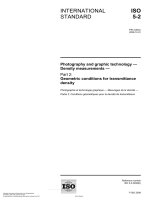
The pipe material should be evaluated in accordance with ISO 9080 or equivalent, where internal pressure
tests are made in accordance with ISO 1167-1 and ISO 1167-2 to find the σLPL-value. The σLPL-value thus
determined shall be at least as high as the corresponding values of the reference curves given in Figure 1 or
Figure 2, as applicable, over the complete range of times.
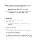
NOTE 1
One equivalent way of evaluation is to calculate the σLPL-value for each temperature (e.g. for 20 °C, 60 °C and
95 °C or 100 °C) individually.
NOTE 2
The reference curves in Figure 1 for Type I PVC-C in the temperature range of 10 °C to 95 °C are derived
from Equation (1):
log t = −109,95 −
21897, 4
43 702,87
× log σ +
+ 50,742 02 × log σ
T
T
2
Copyright International Organization for Standardization
Provided by IHS under license with ISO
No reproduction or networking permitted without license from IHS
(1)
© ISO 2009 – All rights reserved
Not for Resale
--`,,```,,,,````-`-`,,`,,`,`,,`---
ISO 15877-1:2009, Plastics piping systems for hot and cold water installations ― Chlorinated
poly(vinyl chloride) (PVC-C) ― Part 1: General
ISO 15877-2:2009(E)
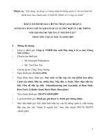
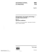
The reference curves in Figure 2 for Type II PVC-C in the temperature range of 10 °C to 100 °C are derived from
Equation (2):
log t = −115,839 −
22 980
45 647,94
× log σ +
+ 54,732 19 × log σ
T
T
(2)
To demonstrate conformance to the reference lines, pipe samples should be tested at the following
temperatures and at various hoop stresses such that, at each of the temperatures given, at least three failure
times fall in each of the following time intervals:
PVC-C Type I:
Temperatures 20 °C; 60 °C to 70 °C; 95 °C;
PVC-C Type I:
Time intervals 10 h to 100 h, 100 h to 1 000 h,1 000 h to 8 760 h and above 8 760 h;
PVC-C Type II:
Temperatures 20 °C; 60 °C to 70 °C; 100 °C;
PVC-C Type II:
Time intervals 10 h to 100 h, 100 h to 1 000 h,1 000 h to 8 760 h and above 8 760 h.
--`,,```,,,,````-`-`,,`,,`,`,,`---
In tests lasting more than 8 760 h, once no failure is reached at a stress and time at least on or above the
reference line, any time after that can be considered as the failure time. Testing should be carried out in
accordance with ISO 1167-1. Conformance to the reference lines should be demonstrated by plotting the
individual experimental results on the graph. At least 97,5 % of them should lie on or above the reference line.
3
© ISO 2009 – All rights reserved
Copyright International Organization for Standardization
Provided by IHS under license with ISO
No reproduction or networking permitted without license from IHS
Not for Resale
ISO 15877-2:2009(E)
Key
X1 time to fracture, expressed in hours
X2 time to fracture, expressed in years
Y
hydrostatic stress, expressed in megapascals
Figure 1 — Reference curves for the expected hydrostatic strength of PVC-C Type I pipe material
--`,,```,,,,````-`-`,,`,,`,`,,`---
4
Copyright International Organization for Standardization
Provided by IHS under license with ISO
No reproduction or networking permitted without license from IHS
© ISO 2009 – All rights reserved
Not for Resale
ISO 15877-2:2009(E)
Key
X1 time to fracture, expressed in hours
X2 time to fracture, expressed in years
Y hydrostatic stress, expressed in megapascals
Figure 2 — Reference curves for the expected hydrostatic strength of PVC-C Type II pipe material
--`,,```,,,,````-`-`,,`,,`,`,,`---
5
© ISO 2009 – All rights reserved
Copyright International Organization for Standardization
Provided by IHS under license with ISO
No reproduction or networking permitted without license from IHS
Not for Resale
ISO 15877-2:2009(E)
4.4
Influence on water intended for human consumption
The material shall conform to ISO 15877-1.
5
General characteristics
5.1
Appearance
When viewed without magnification, the internal and external surfaces of pipes shall be smooth, clean and
free from scoring, cavities and other surface defects to an extent that would prevent conformance with this
part of ISO 15877. The material shall not contain visible impurities. Slight variations in the appearance of the
colour shall be permitted.
The ends of the pipe shall be cleanly cut and square to the axis of the pipe.
5.2
Chamfering
If a chamfer is required, the angle of chamfering shall be between 15° and 45° to the axis of the pipe. When
pipes without chamfer are used, the pipe ends shall be deburred.
5.3
Opacity
PVC-C pipes that are declared to be opaque shall not transmit more than 0,2 % of visible light, when tested in
accordance with ISO 7686.
6
Geometrical characteristics
6.1
6.1.1
General
Dimensions shall be measured in accordance with ISO 3126.
6.1.2 The maximum calculated pipe value, Scalc,max, for the applicable class of service conditions and
design pressure, pD, shall conform to Table 1 or Table 2, as applicable.
Table 1 — Scalc,max-values for PVC-C Type I
Design
pressure
pD
Application class
Class 1
bar a
Class 2
Scalc,max-values b
4
10,0 c
10,0 c
6
7,3
7,1
8
5,5
4,8
10
4,4
4,2
a
1 bar = 0,1 MPa = 0,1 N/mm2 = 105 N/m2.
b
The values are rounded to the first decimal place.
c
The 20 °C, 10 bar, 50 years, cold water requirement, being higher,
determines this value (see Clause 4 of ISO 15877-1:2009).
--`,,```,,,,````-`-`,,`,,`,`,,`---
6
Copyright International Organization for Standardization
Provided by IHS under license with ISO
No reproduction or networking permitted without license from IHS
© ISO 2009 – All rights reserved
Not for Resale
ISO 15877-2:2009(E)
Table 2 — Scalc,max-values for PVC-C Type II
Design pressure
pD
bar
a
Application class
Class 1
4
11,2 b
6
8,0
Class 2
Class 4
Class 5
Scalc,max-values a
11,2 b
11,2 b
7,1
7,6
7,5
4,8
[3,6] c
[2,9] c
8
6,0
5,7
[5,6] c
10
4,8
4,5
[4,5] c
The values are rounded to the first decimal place.
b
The 20 °C, 10 bar, 50 years, cold water requirement, being higher, determines this value (see Clause 4 of
ISO 15877-1:2009).
c
Theoretical values, see Table 4 and Table 6 of ISO 15877-5:2009.
NOTE
The derivation of Scalc,max is provided in Annex A. The method described takes account of the properties of
PVC-C under the service conditions for the classes given in Table 1 of ISO 15877-1:2009.
6.2
Dimensions of pipes
The mean outside diameter, dem, of a pipe shall conform to Table 3.
6.3
Wall thicknesses and their tolerances
6.3.1
General
--`,,```,,,,````-`-`,,`,,`,`,,`---
For any particular class of service conditions, design pressure and nominal size, the minimum wall thickness,
emin, shall be chosen in such a way that the corresponding S series or Scalc value is equal to or less than
Scalc,max as given in Table 1 or Table 2, as applicable.
The wall thickness, e, shall conform to Table 3 in relation to the pipe series S.
The tolerance on the wall thickness, e, shall conform to Table 4.
Table 3 — Diameters and wall thicknesses
Dimensions in millimetres
Nominal size
DN/OD
Nominal outside
diameter
Pipe series
Mean outside diameter
S 6,3
S5
S4
Minimum wall thickness emin and en
dn
dem,min
dem,max
12
14
16
20
25
12
14
16
20
25
12,0
14,0
16,0
20,0
25,0
12,2
14,2
16,2
20,2
25,2
1,4
1,4
1,4
1,5
1,9
1,4
1,4
1,5
1,9
2,3
1,4
1,6
1,8
2,3
2,8
32
40
50
63
75
32
40
50
63
75
32,0
40,0
50,0
63,0
75,0
32,2
40,2
50,2
63,3
75,3
2,4
3,0
3,7
4,7
5,6
2,9
3,7
4,6
5,8
6,8
3,6
4,5
5,6
7,1
8,4
90
110
125
140
160
90
110
125
140
160
90,0
110,0
125,0
140,0
160,0
90,3
110,4
125,4
140,5
160,5
6,7
8,1
9,2
10,3
11,8
8,2
10,0
11,4
12,7
14,6
10,1
12,3
14,0
15,7
17,9
NOTE
Sizes conform to ISO 4065 [1] and are applicable for all classes of service conditions.
7
© ISO 2009 – All rights reserved
Copyright International Organization for Standardization
Provided by IHS under license with ISO
No reproduction or networking permitted without license from IHS
Not for Resale
ISO 15877-2:2009(E)
Table 4 — Tolerances on wall thicknesses
Dimensions in millimetres
Minimum wall thickness
emin
Tolerance
xa
>
u
1,0
2,0
3,0
4,0
5,0
2,0
3,0
4,0
5,0
6,0
0,4
0,5
0,6
0,7
0,8
6,0
7,0
8,0
9,0
10,0
7,0
8,0
9,0
10,0
11,0
0,9
1,0
1,1
1,2
1,3
11,0
12,0
13,0
14,0
15,0
12,0
13,0
14,0
15,0
16,0
1,4
1,5
1,6
1,7
1,8
16,0
17,0
17,0
18,0
1,9
2,0
a
The tolerance is expressed in the form + x0 mm, where x is the value of the
tolerance given. The level of the tolerances conforms to Grade W of ISO 11922-1 [2].
6.3.2
Length of pipes
The effective length, l, of a pipe shall not be less than specified by the manufacturer.
7
Mechanical characteristics
7.1
Resistance to internal pressure
When tested in accordance with the test method specified in Table 5 or Table 6, as applicable, using the
indicated parameters, the pipe shall withstand the hydrostatic (hoop) stress without bursting or leakage.
Table 5 — Test parameters for testing resistance to internal pressure for PVC-C Type I
Requirements
Resistance to
internal pressure
No failure during
the test period
Test parameters for the individual tests
Hydrostatic
(hoop) stress
Test
temperature
Test period
Test method
Number of
test pieces
MPa
°C
h
43
20
1
5,6
95
165
3
4,6
95
1 000
3
ISO 1167-1
3
Test parameters for all tests
a
Sampling procedure
Type of end caps
Orientation of test piece
Type of test b c
a
Types A or B
Vertical
Water-in-air or
water-in-water
The sampling procedure is not specified. For guidance, see ISO/TS 15877-7 [4].
b
Testing at 95 °C shall be done in water-in-air.
c
In case of dispute, testing at 20 °C shall be done in water-in-water.
8
Copyright International Organization for Standardization
Provided by IHS under license with ISO
No reproduction or networking permitted without license from IHS
© ISO 2009 – All rights reserved
Not for Resale
--`,,```,,,,````-`-`,,`,,`,`,,`---
Characteristic
ISO 15877-2:2009(E)
Table 6 — Test parameters for testing resistance to internal pressure for PVC-C Type II
Characteristic
Requirements
Resistance to
internal pressure
No failure during
the test period
Test parameters for the individual tests
Test method
Number of
test pieces
Hydrostatic
(hoop) stress
Test
temperature
Test period
MPa
°C
h
48
20
1
3
5,9
95
165
3
4,7
95
1 000
3
ISO 1167-1
Test parameters for all tests
Sampling procedure
Type of end caps
Orientation of test piece
Type of test b c
a
Types A or B
Vertical
Water-in-air or water-in-water
a
The sampling procedure is not specified. For guidance, see ISO/TS 15877-7 [4].
b
Testing at 95 °C shall be done in water-in-air.
c
In case of dispute, testing at 20 °C shall be done in water-in-water.
7.2
Impact resistance
When tested in accordance with the test method specified in Table 7, using the indicated parameters, the pipe
shall have a true impact rate, TIR, conforming to Table 7. Masses and fall heights of striker for testing impact
resistance are given in Table 8.
Table 7 — Test parameters for testing impact resistance
Impact resistance
(via single impact test)
Requirements
TIR u 10%
Test parameters
Type of striker
Mass of striker
Fall height of striker
Conditioning medium
Test/conditioning temperature
Sampling procedure
a
In case of dispute, air shall be used.
b
The sampling procedure is not specified. For guidance, see ISO/TS 15877-7 [4].
EN 744
b
9
© ISO 2009 – All rights reserved
Copyright International Organization for Standardization
Provided by IHS under license with ISO
No reproduction or networking permitted without license from IHS
d25
Shall conform to Table 8
Shall conform to Table 8
Water or air a
(0 ± 1) °C
Test method
--`,,```,,,,````-`-`,,`,,`,`,,`---
Characteristic
Not for Resale
ISO 15877-2:2009(E)
Table 8 — Masses and fall heights of striker for testing impact resistance
Nominal size
DN/OD
Nominal outside
diameter
dn
Mass of striker a
Fall height of
striker
kg
m
mm
a
7.3
12
14
16
20
25
12
14
16
20
25
0,5
0,5
0,5
0,5
0,5
0,3
0,3
0,4
0,4
0,5
32
40
50
63
75
32
40
50
63
75
0,5
0,5
0,5
0,8
0,8
0,6
0,8
1,0
1,0
1,0
90
110
125
140
160
90
110
125
140
160
0,8
1,0
1,25
1,6
1,6
1,2
1,6
2,0
1,8
2,0
The tolerance on the given mass of the striker is
+ 0,01
0 .
Tensile strength
When tested in accordance with the test method specified in Table 9, using the indicated parameters, the pipe
shall have a tensile strength at yield point conforming to Table 9.
Table 9 — Test parameters for testing tensile strength
Tensile strength
at yield point
8
Requirements
σy W 50 MPa
Test parameters
Speed of testing
Test piece shape and
dimensions
Number of test pieces
Test piece preparation
Initial gauge length
5 mm/min
Shall conform to
ISO 6259-2
5
Machining
(25 ± 1) mm
Test method
ISO 6259-1
Physical characteristics
When tested in accordance with the test methods specified in Table 10 or Table 11, as applicable, using the
indicated parameters, the pipe shall have physical characteristics conforming to the requirements given in the
applicable table.
10
Copyright International Organization for Standardization
Provided by IHS under license with ISO
No reproduction or networking permitted without license from IHS
© ISO 2009 – All rights reserved
Not for Resale
--`,,```,,,,````-`-`,,`,,`,`,,`---
Characteristic
ISO 15877-2:2009(E)
Table 10 — Physical characteristics for PVC-C Type I
Requirements
Test parameters
Vicat softening
temperature (VST)
VST W 110 °C
Shall conform to EN 727
Longitudinal
reversion
u5%
Test temperature
Duration of exposure for:
e u 4 mm
4 mm < e u 16 mm
e > 16 mm
Number of test pieces
(150 ± 2) °C
Thermal stability by
hydrostatic pressure
testing
No bursting or
leakage during
the test period
Sampling procedure
Type of end caps
Orientation of test piece
Type of test
Test temperature
Hydrostatic (hoop) stress
Test period
Number of test pieces
a
a
The pipe shall exhibit
no bubbles or cracks
Test method
EN 727
(30 ± 1) min
(60 ± 1) min
(120 ± 1) min
3
ISO 2505
Air oven
ISO 1167-1
Types A or B
Vertical
Water-in-air
95 °C
3,6 MPa
8760 h
3
--`,,```,,,,````-`-`,,`,,`,`,,`---
Characteristic
The sampling procedure is not specified. For guidance, see ISO/TS 15877-7 [4].
Table 11 — Physical characteristics for PVC-C Type II
Characteristic
Requirements
Test parameters
Vicat softening
temperature (VST)
VST W 115 °C
Shall conform to EN 727
Longitudinal
reversion
u5%
Test temperature
Duration of exposure for:
e u 4 mm
4 mm < e u 16 mm
e > 16 mm
Number of test pieces
(150 ± 2) °C
Thermal stability by
hydrostatic pressure
testing
No bursting or
leakage during
the test period
Sampling procedure
Type of end caps
Orientation of test piece
Type of test
Test temperature
Hydrostatic (hoop) stress
Test period
Number of test pieces
a
a
9
The pipe shall exhibit
no bubbles or cracks
Test method
EN 727
(30 ± 1) min
(60 ± 1) min
(120 ± 1) min
3
ISO 2505
Air oven
ISO 1167-1
Types A or B
Vertical
Water-in-air
100 °C
2,4 MPa
8760 h
3
The sampling procedure is not specified. For guidance, see ISO/TS 15877-7 [4].
Performance requirements
When pipes conforming to this part of ISO 15877 are jointed to each other or to components conforming to
ISO 15877-3, the pipes and the joints shall conform to ISO 15877-5.
10 Adhesives
The adhesive(s) shall be solvent cement and shall be as recommended by the manufacturer of the pipes
and/or fittings.
11
© ISO 2009 – All rights reserved
Copyright International Organization for Standardization
Provided by IHS under license with ISO
No reproduction or networking permitted without license from IHS
Not for Resale
ISO 15877-2:2009(E)
The adhesive(s) shall have no detrimental effects on the properties of the pipe and shall not cause the test
assembly to fail to conform to ISO 15877-5.
NOTE
Relevant specifications and test methods for solvent cements are currently being discussed by WG 6
Adhesives for thermoplastic piping systems of Technical Committee CEN/TC 193, Adhesives.
11 Marking
11.1 General
11.1.1 Marking elements shall be printed or formed directly on the pipe not less than once per metre in such
a way that after storage, handling and installation (e.g. in accordance with ENV 12108 [5]), legibility is
maintained.
NOTE
The manufacturer is not responsible for marking being illegible due to actions such as painting, scratching and
covering of the components, or by use of detergent, etc. on the components unless agreed or specified by the
manufacturer.
11.1.2 Marking shall not initiate cracks or other types of defects which adversely influence the performance
of the pipe.
11.1.3 If printing is used, the colouring of the printed information shall differ from the basic colouring of the
pipe.
11.1.4 The size of the marking shall be such that the marking is legible without magnification.
11.2 Minimum required marking
The minimum required marking of the pipe is specified in Table 12.
Table 12 — Minimum required marking
Aspect
Marking or symbol
Number of this International Standard
Manufacturer’s name and/or trade mark
Nominal outside diameter and nominal wall thickness
Material
ISO 15877
Name or code
e.g. 32 × 3,6
PVC-C-Type I or
PVC-C-Type II a
e.g. Class 2/10 bar
e.g. opaque
Application class combined with design pressure
Opacity b
Manufacturer’s information
c
a
Systems marked PVC-C are assumed to be of PVC-C Type I.
b
If declared by the manufacturer.
c
To provide traceability, the following details shall be given:
a)
the production period, year and month, in figures or in code;
b)
a name or code for the production site if the manufacturer is producing at different sites.
11.3 Additional marking
Pipes conforming to this part of ISO 15877, which are certified by a third party, may be marked accordingly.
NOTE
Attention is drawn to the possible need to include CE marking when required for legislative purposes.
--`,,```,,,,````-`-`,,`,,`,`,,`---
12 Organization for Standardization
Copyright International
Provided by IHS under license with ISO
No reproduction or networking permitted without license from IHS
© ISO 2009 – All rights reserved
Not for Resale
ISO 15877-2:2009(E)
Annex A
(informative)
Derivation of the maximum calculated pipe value, Scalc,max
A.1 General
Annex A specifies the principles regarding the derivation of Scalc,max-values and, hence, of minimum wall
thicknesses, emin, of pipes relative to the classes of service conditions given in Table 1 of ISO 15877-1:2009
and the applicable design pressure, pD.
The design stress, σD, for a particular class of service conditions is calculated from Equation (1) or
Equation (2) of 4.3, or Equation (1) or Equation (2) of ISO 15877-3:2009, using Miner’s rule in accordance
with ISO 13760 [3] and taking into account the applicable class requirements given in Table 1 of ISO 158771:2009 and the service coefficients given in Table A.1.
Table A.1 — Overall service (design) coefficients
Temperature
°C
Overall service (design)
coefficient,
C
TD
1,8
Tmax
1,7
Tmal
1,0
Tcold
2,5
The resulting design stress, σD, has been calculated relative to each class and is given in Table A.2 or
Table A.3, as applicable. The design stress at 20 °C, σcold, relative to a service life of 50 years is 10,0 MPa.
Table A.2 — Design stress for PVC-C Type I
Application class
Design stress
σD a
MPa
a
1
4,38
2
4,16
20 °C/50 years
10,0
Values given are rounded to the second decimal place.
13
© ISO 2009 – All rights reserved
Copyright International Organization for Standardization
Provided by IHS under license with ISO
No reproduction or networking permitted without license from IHS
Not for Resale
--`,,```,,,,````-`-`,,`,,`,`,,`---
A.2 Design stress
ISO 15877-2:2009(E)
Table A.3 — Design stress for PVC-C Type II
Application class
Design stress
σD a
MPa
a
1
4,79
2
4,55
4
4,52
5
2,86
20 °C/50 years
11,2
Values given are rounded to the second decimal place.
A.3 Derivation of the maximum value of Scalc (Scalc,max)
Scalc,max is the smaller value of
either
σ DP
pD
where
σDP
is the design stress in the pipe material taken from Table A.2 or Table A.3, as applicable;
pD
is the design pressure of 4 bar, 6 bar, 8 bar or 10 bar, as applicable, in megapascals.
σ cold
or
pD
where
σcold is the design stress at 20 °C relative to a service life of 50 years;
pD
is the design pressure of 10 bar, in megapascals.
The values of Scalc,max relative to each class of service conditions (see ISO 15877-1) are given in Table 1 or
Table 2, as applicable.
A.4 Use of Scalc,max to determine the wall thickness
The pipe series S and Scalc-values shall be chosen for each application class and design pressure from
Table 3 in such a way that the corresponding pipe series S is not greater than the values of Scalc,max as given
in Table 1 or Table 2, as applicable.
--`,,```,,,,````-`-`,,`,,`,`,,`---
14
Copyright International Organization for Standardization
Provided by IHS under license with ISO
No reproduction or networking permitted without license from IHS
© ISO 2009 – All rights reserved
Not for Resale