Api rp 2d 2014 (2015) (american petroleum institute)
Bạn đang xem bản rút gọn của tài liệu. Xem và tải ngay bản đầy đủ của tài liệu tại đây (1.7 MB, 130 trang )
Operation and Maintenance of
Offshore Cranes
API RECOMMENDED PRACTICE 2D
SEVENTH EDITION, DECEMBER 2014
ERRATA, AUGUST 2015
Special Notes
API publications necessarily address problems of a general nature. With respect to particular circumstances, local,
state, and federal laws and regulations should be reviewed.
Neither API nor any of API's employees, subcontractors, consultants, committees, or other assignees make any
warranty or representation, either express or implied, with respect to the accuracy, completeness, or usefulness of the
information contained herein, or assume any liability or responsibility for any use, or the results of such use, of any
information or process disclosed in this publication. Neither API nor any of API's employees, subcontractors,
consultants, or other assignees represent that use of this publication would not infringe upon privately owned rights.
API publications may be used by anyone desiring to do so. Every effort has been made by the Institute to assure the
accuracy and reliability of the data contained in them; however, the Institute makes no representation, warranty, or
guarantee in connection with this publication and hereby expressly disclaims any liability or responsibility for loss or
damage resulting from its use or for the violation of any authorities having jurisdiction with which this publication may
conflict.
API publications are published to facilitate the broad availability of proven, sound engineering and operating
practices. These publications are not intended to obviate the need for applying sound engineering judgment
regarding when and where these publications should be utilized. The formulation and publication of API publications
is not intended in any way to inhibit anyone from using any other practices.
Any manufacturer marking equipment or materials in conformance with the marking requirements of an API standard
is solely responsible for complying with all the applicable requirements of that standard. API does not represent,
warrant, or guarantee that such products do in fact conform to the applicable API standard.
Users of this Recommended Practice should not rely exclusively on the information contained in this document.
Sound business, scientific, engineering, and safety judgment should be used in employing the information contained
herein.
All rights reserved. No part of this work may be reproduced, translated, stored in a retrieval system, or transmitted by any means,
electronic, mechanical, photocopying, recording, or otherwise, without prior written permission from the publisher. Contact the
Publisher, API Publishing Services, 1220 L Street, NW, Washington, DC 20005.
Copyright © 2014 American Petroleum Institute
Foreword
This recommended practice is under the jurisdiction of the API Subcommittee on Drilling and Production Operations
and was developed in cooperation with the Offshore Operators Committee. Detailed requirements for the design and
construction of offshore cranes are given in API 2C.
The principles provided herein on the operation, inspection and maintenance of offshore cranes are based in part on
an understanding of the cranes’ design and construction. Therefore, this document should be used in conjunction with
API 2C.
Conformance to the intent of the programs and practices recommended herein is intended to result in cranes that
operate safely and efficiently between inspection periods and in accordance with a company's safety and
environmental management system (see API 75).
Each crane owner, qualified crane operator, qualified inspector, and qualified rigger is encouraged to follow the
recommendations outlined herein, and to modify or supplement them with any practices or procedures which are
more appropriate for the type and duty cycle-both past and future-of the crane, provided the minimum
recommendations and the intent of the programs stated herein are met.
The material in this publication represents the contribution of industry representatives of crane users, crane
manufacturers, wire rope manufacturers and ancillary crane device or component manufacturers. It is based on
industry experience and expertise involving worldwide operations.
It should be understood that the crane operating and maintenance practices cover a wide range of crane types and
configurations. Not all practices are applicable to all cranes. When applying this document, care should be taken to
review each item as stated, and use those items specifically applicable to the crane's type, usage, and duty-cycle. It
may be necessary to modify a procedure due to a particular crane requirement. This modification would be wholly
acceptable as long as the original intent of the practice or procedure is met.
The verbal forms used to express the provisions in this specification are as follows:
— the term “shall” denotes a minimum requirement in order to conform to the specification;
— the term “should” denotes a recommendation or that which is advised but not required in order to conform to the
specification;
— the term “may” is used to express permission or a provision that is optional;
— the term “can” is used to express possibility or capability.
Nothing contained in any API publication is to be construed as granting any right, by implication or otherwise, for the
manufacture, sale, or use of any method, apparatus, or product covered by letters patent. Neither should anything
contained in the publication be construed as insuring anyone against liability for infringement of letters patent.
This document was produced under API standardization procedures that ensure appropriate notification and
participation in the developmental process and is designated as an API standard. Questions concerning the
interpretation of the content of this publication or comments and questions concerning the procedures under which
this publication was developed should be directed in writing to the Director of Standards, American Petroleum
Institute, 1220 L Street, NW, Washington, DC 20005. Requests for permission to reproduce or translate all or any part
of the material published herein should also be addressed to the director.
Generally, API standards are reviewed and revised, reaffirmed, or withdrawn at least every five years. A one-time
extension of up to two years may be added to this review cycle. Status of the publication can be ascertained from the
iii
API Standards Department, telephone (202) 682-8000. A catalog of API publications and materials is published
annually by API, 1220 L Street, NW, Washington, DC 20005.
Suggested revisions are invited and should be submitted to the Standards Department, API, 1220 L Street, NW,
Washington, DC 20005,
iv
Contents
Page
1
Scope . . . . . . . . . . . . . . . . . . . . . . . . . . . . . . . . . . . . . . . . . . . . . . . . . . . . . . . . . . . . . . . . . . . . . . . . . . . . . . . . . . 1
2
Normative References. . . . . . . . . . . . . . . . . . . . . . . . . . . . . . . . . . . . . . . . . . . . . . . . . . . . . . . . . . . . . . . . . . . . . 1
3
3.1
3.2
Terms, Definitions, and Abbreviations . . . . . . . . . . . . . . . . . . . . . . . . . . . . . . . . . . . . . . . . . . . . . . . . . . . . . . . 2
Terms and Definitions . . . . . . . . . . . . . . . . . . . . . . . . . . . . . . . . . . . . . . . . . . . . . . . . . . . . . . . . . . . . . . . . . . . . . 2
Abbreviations. . . . . . . . . . . . . . . . . . . . . . . . . . . . . . . . . . . . . . . . . . . . . . . . . . . . . . . . . . . . . . . . . . . . . . . . . . . . 8
4
4.1
4.2
4.3
4.4
4.5
4.6
4.7
4.8
Operation . . . . . . . . . . . . . . . . . . . . . . . . . . . . . . . . . . . . . . . . . . . . . . . . . . . . . . . . . . . . . . . . . . . . . . . . . . . . . . . 9
Crane Operator and Rigger Qualifications and Operating Practices . . . . . . . . . . . . . . . . . . . . . . . . . . . . . . 9
Handling the Load . . . . . . . . . . . . . . . . . . . . . . . . . . . . . . . . . . . . . . . . . . . . . . . . . . . . . . . . . . . . . . . . . . . . . . . 11
Signals . . . . . . . . . . . . . . . . . . . . . . . . . . . . . . . . . . . . . . . . . . . . . . . . . . . . . . . . . . . . . . . . . . . . . . . . . . . . . . . . 12
Personnel Transfer . . . . . . . . . . . . . . . . . . . . . . . . . . . . . . . . . . . . . . . . . . . . . . . . . . . . . . . . . . . . . . . . . . . . . . 13
Refueling. . . . . . . . . . . . . . . . . . . . . . . . . . . . . . . . . . . . . . . . . . . . . . . . . . . . . . . . . . . . . . . . . . . . . . . . . . . . . . . 13
Fire Extinguishers . . . . . . . . . . . . . . . . . . . . . . . . . . . . . . . . . . . . . . . . . . . . . . . . . . . . . . . . . . . . . . . . . . . . . . . 13
Load Test . . . . . . . . . . . . . . . . . . . . . . . . . . . . . . . . . . . . . . . . . . . . . . . . . . . . . . . . . . . . . . . . . . . . . . . . . . . . . . 13
Pull Test . . . . . . . . . . . . . . . . . . . . . . . . . . . . . . . . . . . . . . . . . . . . . . . . . . . . . . . . . . . . . . . . . . . . . . . . . . . . . . . 17
5
5.1
5.2
5.3
5.4
5.5
5.6
Inspection, Testing, and Maintenance . . . . . . . . . . . . . . . . . . . . . . . . . . . . . . . . . . . . . . . . . . . . . . . . . . . . . .
Usage and Inspection . . . . . . . . . . . . . . . . . . . . . . . . . . . . . . . . . . . . . . . . . . . . . . . . . . . . . . . . . . . . . . . . . . . .
Inspection and Load Test Records . . . . . . . . . . . . . . . . . . . . . . . . . . . . . . . . . . . . . . . . . . . . . . . . . . . . . . . . .
Maintenance . . . . . . . . . . . . . . . . . . . . . . . . . . . . . . . . . . . . . . . . . . . . . . . . . . . . . . . . . . . . . . . . . . . . . . . . . . . .
Lubrication . . . . . . . . . . . . . . . . . . . . . . . . . . . . . . . . . . . . . . . . . . . . . . . . . . . . . . . . . . . . . . . . . . . . . . . . . . . . .
Crane Rerating . . . . . . . . . . . . . . . . . . . . . . . . . . . . . . . . . . . . . . . . . . . . . . . . . . . . . . . . . . . . . . . . . . . . . . . . . .
Crane Derating . . . . . . . . . . . . . . . . . . . . . . . . . . . . . . . . . . . . . . . . . . . . . . . . . . . . . . . . . . . . . . . . . . . . . . . . . .
17
17
19
20
21
21
21
6
6.1
6.2
6.3
Wire Rope and Sling Inspection, Maintenance, and Replacement . . . . . . . . . . . . . . . . . . . . . . . . . . . . . . .
General . . . . . . . . . . . . . . . . . . . . . . . . . . . . . . . . . . . . . . . . . . . . . . . . . . . . . . . . . . . . . . . . . . . . . . . . . . . . . . . .
Wire Rope . . . . . . . . . . . . . . . . . . . . . . . . . . . . . . . . . . . . . . . . . . . . . . . . . . . . . . . . . . . . . . . . . . . . . . . . . . . . . .
Slings . . . . . . . . . . . . . . . . . . . . . . . . . . . . . . . . . . . . . . . . . . . . . . . . . . . . . . . . . . . . . . . . . . . . . . . . . . . . . . . . .
22
22
22
24
7
7.1
7.2
7.3
7.4
7.5
7.6
7.7
7.8
7.9
7.10
7.11
Lift Planning . . . . . . . . . . . . . . . . . . . . . . . . . . . . . . . . . . . . . . . . . . . . . . . . . . . . . . . . . . . . . . . . . . . . . . . . . . . .
General . . . . . . . . . . . . . . . . . . . . . . . . . . . . . . . . . . . . . . . . . . . . . . . . . . . . . . . . . . . . . . . . . . . . . . . . . . . . . . . .
Roles and Responsibilities. . . . . . . . . . . . . . . . . . . . . . . . . . . . . . . . . . . . . . . . . . . . . . . . . . . . . . . . . . . . . . . .
Planning the Lift. . . . . . . . . . . . . . . . . . . . . . . . . . . . . . . . . . . . . . . . . . . . . . . . . . . . . . . . . . . . . . . . . . . . . . . . .
Lift Categorization . . . . . . . . . . . . . . . . . . . . . . . . . . . . . . . . . . . . . . . . . . . . . . . . . . . . . . . . . . . . . . . . . . . . . . .
Risk Assessment. . . . . . . . . . . . . . . . . . . . . . . . . . . . . . . . . . . . . . . . . . . . . . . . . . . . . . . . . . . . . . . . . . . . . . . .
Personnel Transfer . . . . . . . . . . . . . . . . . . . . . . . . . . . . . . . . . . . . . . . . . . . . . . . . . . . . . . . . . . . . . . . . . . . . . .
Personnel Qualifications . . . . . . . . . . . . . . . . . . . . . . . . . . . . . . . . . . . . . . . . . . . . . . . . . . . . . . . . . . . . . . . . .
Documentation of a Lift Plan . . . . . . . . . . . . . . . . . . . . . . . . . . . . . . . . . . . . . . . . . . . . . . . . . . . . . . . . . . . . . .
Approval of Lift Plans . . . . . . . . . . . . . . . . . . . . . . . . . . . . . . . . . . . . . . . . . . . . . . . . . . . . . . . . . . . . . . . . . . . .
Changes to lift Plans . . . . . . . . . . . . . . . . . . . . . . . . . . . . . . . . . . . . . . . . . . . . . . . . . . . . . . . . . . . . . . . . . . . . .
Summary Questions for a Safe Lift . . . . . . . . . . . . . . . . . . . . . . . . . . . . . . . . . . . . . . . . . . . . . . . . . . . . . . . . .
25
25
26
27
29
29
30
30
30
31
31
31
8
8.1
8.2
8.3
Personnel Training Qualifications . . . . . . . . . . . . . . . . . . . . . . . . . . . . . . . . . . . . . . . . . . . . . . . . . . . . . . . . . .
Qualified Rigger. . . . . . . . . . . . . . . . . . . . . . . . . . . . . . . . . . . . . . . . . . . . . . . . . . . . . . . . . . . . . . . . . . . . . . . . .
Qualified Crane Operator . . . . . . . . . . . . . . . . . . . . . . . . . . . . . . . . . . . . . . . . . . . . . . . . . . . . . . . . . . . . . . . . .
Qualified Crane Inspector. . . . . . . . . . . . . . . . . . . . . . . . . . . . . . . . . . . . . . . . . . . . . . . . . . . . . . . . . . . . . . . . .
31
31
32
32
Contents
Page
9
9.1
9.2
9.3
9.4
9.5
9.6
9.7
9.8
9.9
9.10
9.11
9.12
9.13
9.14
9.15
9.16
Temporary Crane Installation . . . . . . . . . . . . . . . . . . . . . . . . . . . . . . . . . . . . . . . . . . . . . . . . . . . . . . . . . . . . . .
Planning the Installation . . . . . . . . . . . . . . . . . . . . . . . . . . . . . . . . . . . . . . . . . . . . . . . . . . . . . . . . . . . . . . . . . .
Installing the Temporary Cranes . . . . . . . . . . . . . . . . . . . . . . . . . . . . . . . . . . . . . . . . . . . . . . . . . . . . . . . . . . .
Testing and Inspecting the Installation . . . . . . . . . . . . . . . . . . . . . . . . . . . . . . . . . . . . . . . . . . . . . . . . . . . . . .
Usage . . . . . . . . . . . . . . . . . . . . . . . . . . . . . . . . . . . . . . . . . . . . . . . . . . . . . . . . . . . . . . . . . . . . . . . . . . . . . . . . .
Crane Design . . . . . . . . . . . . . . . . . . . . . . . . . . . . . . . . . . . . . . . . . . . . . . . . . . . . . . . . . . . . . . . . . . . . . . . . . . .
Crane Equipment. . . . . . . . . . . . . . . . . . . . . . . . . . . . . . . . . . . . . . . . . . . . . . . . . . . . . . . . . . . . . . . . . . . . . . . .
Load Test Requirements. . . . . . . . . . . . . . . . . . . . . . . . . . . . . . . . . . . . . . . . . . . . . . . . . . . . . . . . . . . . . . . . . .
Preventative Maintenance . . . . . . . . . . . . . . . . . . . . . . . . . . . . . . . . . . . . . . . . . . . . . . . . . . . . . . . . . . . . . . . .
Work History . . . . . . . . . . . . . . . . . . . . . . . . . . . . . . . . . . . . . . . . . . . . . . . . . . . . . . . . . . . . . . . . . . . . . . . . . . .
Rental Checklist. . . . . . . . . . . . . . . . . . . . . . . . . . . . . . . . . . . . . . . . . . . . . . . . . . . . . . . . . . . . . . . . . . . . . . . . .
Tie-down Weld Design . . . . . . . . . . . . . . . . . . . . . . . . . . . . . . . . . . . . . . . . . . . . . . . . . . . . . . . . . . . . . . . . . . .
Torque Procedure . . . . . . . . . . . . . . . . . . . . . . . . . . . . . . . . . . . . . . . . . . . . . . . . . . . . . . . . . . . . . . . . . . . . . . .
Weld Procedure . . . . . . . . . . . . . . . . . . . . . . . . . . . . . . . . . . . . . . . . . . . . . . . . . . . . . . . . . . . . . . . . . . . . . . . . .
Load Test . . . . . . . . . . . . . . . . . . . . . . . . . . . . . . . . . . . . . . . . . . . . . . . . . . . . . . . . . . . . . . . . . . . . . . . . . . . . . .
Load Test Procedure . . . . . . . . . . . . . . . . . . . . . . . . . . . . . . . . . . . . . . . . . . . . . . . . . . . . . . . . . . . . . . . . . . . . .
Inspection of Temporary Cranes after Installation . . . . . . . . . . . . . . . . . . . . . . . . . . . . . . . . . . . . . . . . . . . .
32
32
33
33
33
34
34
35
35
36
36
36
36
37
37
37
37
Annex A (informative) Crane Operation . . . . . . . . . . . . . . . . . . . . . . . . . . . . . . . . . . . . . . . . . . . . . . . . . . . . . . . . . . 38
Annex B (informative) Usage, Inspection, Testing, and Maintenance . . . . . . . . . . . . . . . . . . . . . . . . . . . . . . . . . . 40
Annex C (informative) Crane-assisted Personnel Transfer . . . . . . . . . . . . . . . . . . . . . . . . . . . . . . . . . . . . . . . . . . 51
Annex D (normative) Load Testing . . . . . . . . . . . . . . . . . . . . . . . . . . . . . . . . . . . . . . . . . . . . . . . . . . . . . . . . . . . . . . 57
Annex E (informative) Crane Maintenance . . . . . . . . . . . . . . . . . . . . . . . . . . . . . . . . . . . . . . . . . . . . . . . . . . . . . . . . 61
Annex F (normative) Wire Rope and Sling Inspection, Maintenance, and Replacement . . . . . . . . . . . . . . . . . . 62
Annex G (informative) Lift Categories . . . . . . . . . . . . . . . . . . . . . . . . . . . . . . . . . . . . . . . . . . . . . . . . . . . . . . . . . . . . 76
Annex H (normative) Training . . . . . . . . . . . . . . . . . . . . . . . . . . . . . . . . . . . . . . . . . . . . . . . . . . . . . . . . . . . . . . . . . . 79
Annex I (informative) Loading and Unloading Offshore Support Vessels . . . . . . . . . . . . . . . . . . . . . . . . . . . . . 117
Bibliography . . . . . . . . . . . . . . . . . . . . . . . . . . . . . . . . . . . . . . . . . . . . . . . . . . . . . . . . . . . . . . . . . . . . . . . . . . . . . . . 120
Figures
1
Standard Hand Signals for Controlling Crane Operations . . . . . . . . . . . . . . . . . . . . . . . . . . . . . . . . . . . . . .
2
Usage/Inspection/Inspector Qualification Matrix. . . . . . . . . . . . . . . . . . . . . . . . . . . . . . . . . . . . . . . . . . . . . .
B.1 Tilt Method . . . . . . . . . . . . . . . . . . . . . . . . . . . . . . . . . . . . . . . . . . . . . . . . . . . . . . . . . . . . . . . . . . . . . . . . . . . . .
B.2 Depression Measurement Method. . . . . . . . . . . . . . . . . . . . . . . . . . . . . . . . . . . . . . . . . . . . . . . . . . . . . . . . . .
B.3 Rotation Method . . . . . . . . . . . . . . . . . . . . . . . . . . . . . . . . . . . . . . . . . . . . . . . . . . . . . . . . . . . . . . . . . . . . . . . .
D.1 Capacity vs. Radius for a Typical Crane . . . . . . . . . . . . . . . . . . . . . . . . . . . . . . . . . . . . . . . . . . . . . . . . . . . . .
D.2 Example of a Typical Load Chart . . . . . . . . . . . . . . . . . . . . . . . . . . . . . . . . . . . . . . . . . . . . . . . . . . . . . . . . . . .
F.1 Three Basic Components of Wire Rope . . . . . . . . . . . . . . . . . . . . . . . . . . . . . . . . . . . . . . . . . . . . . . . . . . . . .
F.2 Showing Distance of One Rope Lay . . . . . . . . . . . . . . . . . . . . . . . . . . . . . . . . . . . . . . . . . . . . . . . . . . . . . . . .
F.3 Measurement-Diameter. . . . . . . . . . . . . . . . . . . . . . . . . . . . . . . . . . . . . . . . . . . . . . . . . . . . . . . . . . . . . . . . . . .
F.4 Core Failures in Rotation-Resistant Wire Rope . . . . . . . . . . . . . . . . . . . . . . . . . . . . . . . . . . . . . . . . . . . . . . .
F.5 Valley Breaks . . . . . . . . . . . . . . . . . . . . . . . . . . . . . . . . . . . . . . . . . . . . . . . . . . . . . . . . . . . . . . . . . . . . . . . . . . .
14
20
46
47
48
57
58
62
63
64
65
65
Contents
Page
F.6
F.7
F.8
F.9
F.10
F.11
H.1
H.2
H.3
H.4
H.5
H.6
H.7
H.8
H.9
H.10
H.11
H.12
Right and Wrong Way to Measure Wire Rope Diameter . . . . . . . . . . . . . . . . . . . . . . . . . . . . . . . . . . . . . . . . 67
Transferring Rope from Reel to Drum. . . . . . . . . . . . . . . . . . . . . . . . . . . . . . . . . . . . . . . . . . . . . . . . . . . . . . . 69
Method of Installing Wedge-socket Attachment . . . . . . . . . . . . . . . . . . . . . . . . . . . . . . . . . . . . . . . . . . . . . . 71
Choker Configuration . . . . . . . . . . . . . . . . . . . . . . . . . . . . . . . . . . . . . . . . . . . . . . . . . . . . . . . . . . . . . . . . . . . . 73
Rated Sling Capacity Calculation Example (Included Angle) . . . . . . . . . . . . . . . . . . . . . . . . . . . . . . . . . . . 73
Rated Sling Capacity Calculation Example (Horizontal Angle) . . . . . . . . . . . . . . . . . . . . . . . . . . . . . . . . . . 74
Pre-lift Rigging Hardware and Sling Testing Form . . . . . . . . . . . . . . . . . . . . . . . . . . . . . . . . . . . . . . . . . . . . 86
Rigging Hitches Testing Form . . . . . . . . . . . . . . . . . . . . . . . . . . . . . . . . . . . . . . . . . . . . . . . . . . . . . . . . . . . . . 90
Hand Signal Testing Form . . . . . . . . . . . . . . . . . . . . . . . . . . . . . . . . . . . . . . . . . . . . . . . . . . . . . . . . . . . . . . . . 93
Qualified Rigger Card Example . . . . . . . . . . . . . . . . . . . . . . . . . . . . . . . . . . . . . . . . . . . . . . . . . . . . . . . . . . . . 93
Pre-use Daily Inspection Testing Form. . . . . . . . . . . . . . . . . . . . . . . . . . . . . . . . . . . . . . . . . . . . . . . . . . . . . . 99
Pre-use Inspection Checklist . . . . . . . . . . . . . . . . . . . . . . . . . . . . . . . . . . . . . . . . . . . . . . . . . . . . . . . . . . . . . 100
Hand Signal Testing Form . . . . . . . . . . . . . . . . . . . . . . . . . . . . . . . . . . . . . . . . . . . . . . . . . . . . . . . . . . . . . . . 102
On-board (Static) Lift Procedures Testing Form . . . . . . . . . . . . . . . . . . . . . . . . . . . . . . . . . . . . . . . . . . . . . 107
Off-board (Dynamic) Lift Procedures Testing Form . . . . . . . . . . . . . . . . . . . . . . . . . . . . . . . . . . . . . . . . . . 108
Blind Lift Procedures Testing Form . . . . . . . . . . . . . . . . . . . . . . . . . . . . . . . . . . . . . . . . . . . . . . . . . . . . . . . 109
Blind Lift Procedures Example Certificate . . . . . . . . . . . . . . . . . . . . . . . . . . . . . . . . . . . . . . . . . . . . . . . . . . 110
Crane Inspector Example Certificate . . . . . . . . . . . . . . . . . . . . . . . . . . . . . . . . . . . . . . . . . . . . . . . . . . . . . . 116
Table
1
Static/Onboard Test Load and Radius . . . . . . . . . . . . . . . . . . . . . . . . . . . . . . . . . . . . . . . . . . . . . . . . . . . . . . 16
Operation and Maintenance of Offshore Cranes
1
Scope
1.1 This recommended practice establishes general principles for the safe operation and maintenance of
offshore pedestal-mounted revolving cranes on fixed or floating offshore platforms, offshore support vessels,
jackup drilling rigs, semi-submersible drilling rigs and other types of mobile offshore drilling units (MODUs).
This document also provides requirements and recommendations for personnel training, lift planning, preuse inspection, and testing of temporary cranes that are erected offshore.
1.2
Typical applications can include, but are not limited to the following.
a) Offshore oil exploration and production applications; these cranes are typically mounted on a fixed
(bottom-supported) structure, floating platform structure, or ship-hulled vessel used in drilling and
production operations for offshore minerals and energy.
b) Shipboard applications; these lifting devices (rated for 10,000 lbs [4536 kg] or more) are mounted on
surface-type vessels and are used to move materials, containers, ROVs, diving bells, pipeline, subsea
components, and other materials on the vessel, between vessels, into the sea, or to the sea bed.
c) Heavy-lift applications; cranes for heavy-lift applications are mounted on barges, self-elevating vessels or
other vessels, and are used in construction and salvage operations above and below the sea surface.
1.3 Equipment (e.g. davits, launch frames) used only for launching life-saving appliances (life boats or life
rafts) are not included in the scope of this recommended practice.
1.4 Lifting devices not covered by this document should be operated, inspected, and maintained in
accordance with the manufacturer’s recommendations.
2
Normative References
The following referenced documents are indispensable for the application of this document. For dated
references, only the edition cited applies. For undated references, the latest edition of the referenced
document (including any amendments) applies.
API RP 2A-WSD, Recommended Practice for Planning, Designing and Constructing fixed Offshore
Platforms−Working Stress Design
API Spec 2C, Offshore Pedestal-mounted Cranes
API Spec 9A, Specification for Wire Rope
API RP 9B, Application, Care and Use of Wire Rope for Oil Field Service
ASME 1, B30.9, Slings
AWS 2, D1.1, Structural Welding Code—Steel
WRTB 3, Wire Rope Sling User’s Manual
1 ASME International, 2 Park Avenue, New York, NY 10016-5990, www.asme.org.
2 American Welding Society, 8669 NW 36 Street, #130, Miami, Florida 33166-6672, www.aws.org.
1
2
API RECOMMENDED PRACTICE 2D
WRTB, Wire Rope User’s Manual
WSTDA RS-1 4, Recommended Standard for Synthetic Polyester Roundslings
WSTDA WS-1, Recommended Standard for Synthetic Web Slings
3
3.1
Terms, Definitions, and Abbreviations
Terms and Definitions
For the purposes of this document, the following definitions apply.
3.1.1
authorized surveyor
A person who works for a third-party certifying authority who is hired to inspect the crane.
3.1.2
auxiliary hoist line
whip line
A secondary hoist rope (if present) on a crane.
3.1.3
anti-two-blocking
A means to protect hoist ropes, structural components, and machinery from damage that can occur when
two sheave groups (e.g. load block and boom tip) come into contact as the hoist cable is drawn in.
3.1.4
bearing raceway
The surface of the bearing rings which contact the rolling element (balls or rollers) of the swing-bearing
assembly.
3.1.5
boom
A member hinged to the revolving upper-structure and used for supporting the hoist tackle.
3.1.6
boom angle
The angle above or below horizontal of the longitudinal axis of the base boom section.
3.1.7
boom angle indicator
An accessory that indicates the angle of the boom above horizontal.
3.1.8
boom hoist
A mechanism responsible for raising and lowering the boom.
3.1.9
boom length
The straight-line distance from the centerline of boom foot-pin to the centerline of the boom-point main load
hoist sheave pin, measured along the longitudinal axis of the boom.
3 Wire Rope Technical Board, 7011A Manchester Blvd., #178, Alexandria, VA 22310-3203,
www.wireropetechnicalboard.org.
4 Web Sling Tie Down Association, 2105 Laurel Bush Road, Suite 201, Bel Air, MD 21015, www.wstda.com.
OPERATION AND MAINTENANCE OF OFFSHORE CRANES
3
3.1.10
boom stop
A device used to prevent the boom from falling backwards in the case of high winds or a sudden release of
load.
3.1.11
boom tip extension
jib
An extension attached to the boom point to provide added boom length for lifting specified loads.
3.1.12
brake
A device used for holding, retarding, or stopping motion.
3.1.13
bridle sling
A multi-leg sling attached to a single point ring.
3.1.14
cab
An enclosure for the operator and the machine operation controls.
3.1.15
certifying authority
A third-party organization used to certify and approve the design, fabrication, equipment and operation of the
crane.
3.1.16
clutch
A means for engagement or disengagement of power.
3.1.17
counterweight
Weight used to supplement the weight of the machine in providing stability for lifting working loads and
usually attached to the rear of the revolving upper-structure.
3.1.18
crane
Power-operated equipment that can hoist, lower, slew and horizontally move a suspended load.
3.1.19
crane owner
The individual, partnership, firm, or corporation who owns the crane.
NOTE For the purposes of this document, a crane owner can be the lease operator (i.e. oil company), drilling or well
service contractor, vessel owner, or company that provides temporary crane service.
3.1.20
critical component
Any component of the crane assembly devoid of redundancy and/or auxiliary restraining devices whose
failure would result in an uncontrolled descent of the load or uncontrolled rotation of the upper-structure.
3.1.21
derate
To reduce the lifting capacity of a crane due to damage or deterioration of a critical component.
4
API RECOMMENDED PRACTICE 2D
3.1.22
designated
Selected or assigned by the employer or the employer’s representative as being qualified to perform specific
duties.
3.1.23
enclosure
A structure that provides environmental protection for the machine.
3.1.24
fixed platform
A bottom-supported stationary structure without significant movement in response to waves and currents in
operating conditions.
EXAMPLE
Fixed platforms with jacket and pile supports, jack-up rigs, and submersible bottom-supported rigs are
similar in that they are effectively stationary.
3.1.25
gantry
mast
A structural frame, extending above the machinery deck or upper-structure to which the boom support ropes
are reeved.
3.1.26
hands-on proficiency
A physical means of verifying a person’s dexterity, coordination, and familiarity with rigging and overall
machine functions and characteristics.
3.1.27
hoisting
The process of lifting.
3.1.28
hoist rope
Wire rope involved in the process of lifting.
3.1.29
hook block
Block with a hook attached used in lifting service.
NOTE
A hook block can have a single sheave for double or triple line or multiple sheaves for four or more parts of line.
3.1.30
hook load
The load being lifted, including the weight of all rigging.
3.1.31
hook rollers
A means to connect the upper structure to the foundation or pedestal by using rollers to prevent the revolving
upper structure from toppling.
3.1.32
in-service
When a crane is capable of operating in a safe manner in accordance with the capacities shown on the
posted load chart.
NOTE
In-service conditions can be with the boom out of the boom rest or in the boom rest (stowed).
OPERATION AND MAINTENANCE OF OFFSHORE CRANES
5
3.1.33
king pin
Vertical pin or shaft that acts as a rotation-centering device and connects the revolving upper-structure and
base mounting.
3.1.34
king post
A fixed tubular member that acts as a centerline of rotation for the revolving upper structure and as the
connective member to the platform.
3.1.35
lifting authority
An individual with the appropriate knowledge, training, skills and experience to carry out the responsibilities
as determined by the crane owner or Person in Charge (PIC).
3.1.36
load line
hoist line
The main hoist rope.
3.1.37
load ratings
Crane ratings in pounds (kilograms) established by the manufacturer.
3.1.38
log
A means to record activities conducted.
EXAMPLE
Record, a record book, a logbook, a computerized database, or an electronic data collector.
3.1.39
luffing
The operation of changing boom angle in a vertical plane (in effect changing the working radius).
3.1.40
offboard/dynamic lift
A crane lifting a load from or to anywhere not on the platform/vessel that the crane is mounted on (from/to
supply boats, for example).
3.1.41
out-of-service
When a crane is not capable of operating in a safe manner.
NOTE
Out-of-service conditions can be with the boom out of the boom rest or in the boom rest (stowed).
3.1.42
overhaul ball
The weight on a single part line used to pull the wire rope off the drum with gravitational assistance.
3.1.43
pawl
dog
A mechanical device that prevents motion in one or more directions.
3.1.44
pedestal
base
The supporting substructure upon which the revolving upper-structure is mounted.
6
API RECOMMENDED PRACTICE 2D
3.1.45
pendant line
A standing (not running) rope of specified length with fixed end connections.
3.1.46
pull test
A load that is applied to the crane structure that will not exceed 100 % of the crane’s onboard rated capacity
as identified on the crane’s load chart.
NOTE
This is not a load test as described in 4.7.2 and Annex D.
3.1.47
qualified
A person who, by possession of a recognized degree, certificate of professional standing, or who by
extensive knowledge, training, and experience, has successfully demonstrated the ability to solve or resolve
problems relating to the subject matter and work.
3.1.48
qualified crane operator
A person who performs the act or process of raising or lowering a load using a mechanical or nonmechanical crane.
3.1.49
qualified crane inspector
A person who conducts the necessary inspection of cranes based on usage, condition, and performance to
ensure conformance with manufacturer’s specifications, regulatory requirements (as applicable), any other
pertinent criteria, and the provisions of this RP.
3.1.50
qualified rigger
Anyone who attaches or detaches loads or loose gear to lifting devices.
3.1.51
rated capacity
The rated load or safe working load (SWL) at specified radii as established by the manufacturer which are
the maximum loads at those radii for the conditions specified.
3.1.52
rerate
The act of changing the lifting capacity or operations of a crane.
NOTE
Refer to 5.5.
3.1.53
restricted service
The usage of a crane or lifting device with limited operational deficiencies that have been evaluated and
approved by responsible parties (e.g. crane owner, inspector, etc.).
3.1.54
reeving
A rope system where the rope travels around drums and sheaves.
3.1.55
roller path
The surface upon which the rollers that support the revolving upper-structure bear.
NOTE
A roller path can accommodate cone rollers, cylindrical rollers, or live rollers.
OPERATION AND MAINTENANCE OF OFFSHORE CRANES
7
3.1.56
rolling element
The balls or rollers contained between the rings of the swing bearing.
3.1.57
rope
Wire rope, unless otherwise specified.
3.1.58
rotation-resistant rope
A wire rope consisting of an inner layer of strand laid in one direction covered by a layer of strand laid in the
opposite direction.
NOTE
rotate.
A rotation-resistant rope has the effect of counteracting torque by reducing the tendency of the finished rope to
3.1.59
running rope
A rope which travels around sheaves or drums.
3.1.60
safe working load
SWL
rated capacity
The maximum rated load within crane rated capacity for the given operating conditions.
3.1.61
sling
An assembly that connects the load to the material handling equipment.
3.1.62
static/onboard lift
A crane lifting a load from and to the deck of the platform/vessel that the crane is mounted on.
3.1.63
swing
slewing
Rotation of the upper-structure for movement of loads in a horizontal direction about the axis of rotation.
3.1.64
swing bearing
swing circle
A combination of rings with balls or rollers capable of sustaining radial, axial, and moment loads of the
revolving upper-structure with boom and load.
3.1.65
swing-circle assembly
The swing-circle assembly is the connecting component between the crane revolving upper structure and the
pedestal for cranes of certain types.
NOTE
The swing-circle assembly allows crane rotation and sustains the moment, axial, and radial loads imposed by
crane operation.
3.1.66
swing gear
ring gear
External or internal gear with which the swing pinion on the revolving upper-structure meshes to provide
swing motion.
8
API RECOMMENDED PRACTICE 2D
3.1.67
swivel
A load-carrying member with thrust bearings that allows the load to rotate.
3.1.68
tailgate meeting
toolbox talk
Work team meetings held at the work site prior to the job starting to review potential hazards and discuss
aspects of planned operations.
NOTE
Normally consists of crew members and any supervisor or technical resources required to perform the work.
3.1.69
temporary crane
aka self-erecting, leapfrog or bootstrap cranes
A lifting device that is not part of the original platform design and installed for a specific application or task
and will not remain as a permanent part of the facility.
NOTE
A temporary crane can be certified to API 2C or other justification by engineering analysis, review and
materials of construction.
3.1.70
two-blocking
The condition when the lower load block, hook assembly or fastline ball contacts the upper load block or
boom-point sheave assembly.
3.1.71
wire rope
A flexible, multi-wired member usually consisting of a core member around which a number of multi-wired
strands are “laid” or helically wound.
3.1.72
working load
The external load in pounds (kilograms), applied to the crane including the weight of load-attaching
equipment such as load block, shackles, and slings.
NOTE
3.2
The maximum allowable working load for a given condition is the safe working load (SWL).
Abbreviations
For the purposes of this document, the following abbreviations apply.
JSA
job safety analysis
JSEA
job safety environment analysis
LOTO
lock-out, tag-out
MODU
mobile offshore drilling unit
NDE
nondestructive examination
OIM
offshore installation manager
OTM
over-turning moment
PIC
person in charge
PFD
personal flotation device
PPE
personal protective equipment
OPERATION AND MAINTENANCE OF OFFSHORE CRANES
PTW
permit to work
SDS
safety data sheet [formerly known as material safety data sheet (MSDS)]
SWL
safe working load
4
9
Operation
4.1
Crane Operator and Rigger Qualifications and Operating Practices
4.1.1
Crane Operators
Only the following personnel should operate cranes:
a)
qualified crane operators who have met the requirements of 4.1.2;
b)
trainees under the direct supervision of a qualified crane operator;
c)
appropriate maintenance and supervisory personnel, when it is necessary for them to do so in the
performance of their duties;
d)
qualified inspectors in the performance of their inspection duties.
4.1.2
Qualifications for Crane Operators
4.1.2.1 Crane operators shall meet the requirements of a qualified crane operator in 8.2 and Annex H.3.
4.1.2.3 The employer shall ensure that crane operator qualifications are maintained, at a minimum every 4
years, through requalification. This shall also include current vision and medical condition evaluations as in
accordance with 4.1.2.1.
4.1.3
Riggers
Load rigging shall only be performed by a qualified rigger.
4.1.4
Qualification for Riggers
Riggers shall meet the minimum requirements of a qualified rigger contained in 8.1 and Annex H.2
4.1.5
Operating Practices
4.1.5.1 The qualified crane operator (herein also called crane operator) is responsible for those operations
under his or her direct control. Whenever there is any doubt as to safety, the crane operator should have the
authority to stop and refuse to handle loads or continue operations as safety dictates. See Annex A for
additional safety considerations.
4.1.5.2 The crane operator should be aware of the operating characteristics of the crane. Mechanical and
non-mechanical cranes can require different operating techniques, especially with regards to engine speed,
control operation, control arrangement and braking. Upon initial purchase, the crane manufacturer should
provide operating instructions or be consulted for specific information.
4.1.5.3 The crane operator should be familiar with the equipment and its proper care. If adjustments or
repairs to the crane are necessary, or any deficiencies that impair safe operation are known, the crane
should be taken out of service or its operations restricted to eliminate the unsafe condition. See 5.1.1 for
restricted service conditions.
4.1.5.4 Before starting the crane, the crane operator should verify the following:
a)
the pre-use inspection outlined in Annex B has been completed;
10
API RECOMMENDED PRACTICE 2D
b)
all controls are in the “off” or “neutral” position;
c)
all personnel are in the clear.
4.1.5.5 For mechanical cranes, the crane operator should operationally test the brakes each time a load
approaching the rated load is to be handled. Prior to raising the load, exposed brakes should be warmed and
rusted surfaces on the drums cleaned by raising and lowering the boom and load brakes under slight
pressure.
4.1.5.6 When handling loads, the crane operator shall not start machine movement unless the load is within
his or her range of vision or they are in contact with the appointed signal person who has given the
appropriate signal for movement.
4.1.5.7 The crane operator should respond to signals only from the appointed signal person but should
obey an emergency stop signal at any time, no matter who gives the signal.
4.1.5.8 The crane operator should verify that the appropriate onboard/static and offboard/dynamic load
rating charts are in place for the crane configuration in use (i.e. boom length, load line reeving,
counterweight, jib, etc.).
4.1.5.9 Before leaving the control station unattended for a prolonged period, the crane operator should:
a)
land any attached load;
b)
disengage the master clutch, where applicable;
c)
set all locking devices;
d)
put controls in the off or neutral position;
e)
stop the prime mover;
f)
ensure that no component of the crane will interfere with normal helicopter flight operations.
NOTE On unattended control stations, some operations (e.g. wireline) require the crane to be left attached to the
suspended load (e.g. lubricator stabbed and resting on the tree connection). This is an acceptable practice as long as the
procedures listed above have been followed and a safe work plan has been conducted.
4.1.5.10 The crane should be secured against swinging when not in use.
4.1.5.11 The crane operator should be aware of heat sources such as natural gas engines, flares, or any
other heat source that exhausts near the crane. Stress corrosion cracking, paint damage, accelerated
corrosion, and loss of lubricant can result in reduced service life of components.
4.1.5.12 If power or a necessary control function fails during operation, the crane operator should:
a)
set all brakes and locking devices;
b)
move all clutch or other power controls to the off or neutral position; and
c)
if practical, land the suspended load by controlled lowering and stopping.
4.1.5.13 Where cranes are positioned in the proximity of helidecks or approach/take-off zones, they should
not be operated while the helicopter is landing or taking off. The boom should be positioned and secured
against swinging so there is no interference with flight operations. The crane operator should not be at the
control station during helicopter landing/take-off operations, unless the crane operator is in direct voice
communication with the helicopter pilot.
OPERATION AND MAINTENANCE OF OFFSHORE CRANES
11
4.1.5.14 Where cranes are to be used at night, the crane operator should ensure that there is sufficient
lighting for safe operation. The load and landing area should be illuminated.
4.1.5.15 Field welding shall not be performed on load hooks or sling hooks. Hooks should not be exposed
to excessive heat.
4.1.5.16 The crane operator shall keep and maintain a log of the pre-use inspection with the name, date,
and time of inspection. This record should be kept in an appropriate location. See A.1.3 for the appropriate
location for storing logs.
4.2
4.2.1
Handling the Load
The Load
4.2.1.1 Crane lifting capacities are based on relative motion conditions between the crane and the load to
be handled. All cranes shall have one onboard/static and at least one offboard/dynamic load rating chart,
developed specifically for each crane. The charts shall be derived in accordance with the procedures
outlined in API 2C that were applicable at the time of manufacture or subsequent editions, at the discretion of
the crane owner. Other qualified sources, such as an API 2C-licensed crane manufacturer, authorized
surveyor, or an engineer experienced in the design of the crane, as determined by the crane owner, may be
used.
4.2.1.2 The appropriate load-rating chart for the configuration in use shall be visible to the crane operator at
the control station.
4.2.1.3 The crane operator should verify that the hook load is within the crane’s applicable onboard/static or
offboard/dynamic rated load at the radius at which the load is to be lifted. See A.1.4 for clarification of hook
load.
4.2.2
Attaching the Load
4.2.2.1 The load should be attached to the hook by means of slings or other suitable devices. The latch
should be closed to secure loose slings.
4.2.2.2 The hoist rope should not be wrapped around the load.
4.2.2.3 Sling use should be in accordance with the guidelines of 6.3.2 and A.1.5.
4.2.3
Moving the Load
4.2.3.1 Guidance on procedures for moving the load can be found in A.2.
4.2.3.2 No external forces should be applied to suspended loads that will create significant side loading of
the boom. Care should be taken when swinging the crane so as to minimize the pendulum action of the hook
and suspended load.
4.2.3.3 Cranes should not be used for dragging loads unless properly rigged for a vertical pull not
exceeding the rated capacity of the crane or rigging.
4.2.3.4 The crane operator should be aware of the effect of velocity and weight of the load when lowering
to minimize shock load.
4.2.3.5 The crane operator shall not hoist, lower or swing while any personnel are on the load or hook
(other than in a personnel carrier or basket).
12
API RECOMMENDED PRACTICE 2D
4.2.3.6 The crane operator should avoid moving loads over personnel. Loads that are suspended by use of
slings or hoists should be blocked or cribbed before personnel are permitted to work beneath or between
them.
4.2.3.7 No fewer than five full wraps of rope should remain on the drum(s) in any operating condition. Due
consideration should be given to the hoist manufacturer’s recommendations, especially for breakaway
anchor-type hoists.
4.2.3.8 When two or more cranes are used to lift one load, one Qualified Crane Operator or Lifting Authority
should be responsible for the operation. The responsible crane operator should analyze the operation, and
instruct all personnel involved in the proper positioning, rigging of the load and the movements to be made.
4.2.3.9 Appropriate tag or restraining lines should be used where necessary to control the load.
4.2.3.10 When a crane is to be operated at a fixed radius, the boom hoist auxiliary holding device, where
fitted, should be engaged, especially in the case of mechanical cranes or those without automatic pawl
control.
4.3
Signals
4.3.1
Standard Signals
Signals between the crane operator and the designated signal person should be discernible, audibly or
visually, at all times. The crane operator should not respond unless signals are clearly understood.
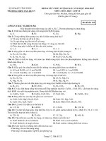
4.3.2
Hand Signals
Recommended standard hand signals are identified in Figure 1. This figure has been supplemented with
hand signals for articulating boom cranes. For articulating boom cranes, some of the hand signals/hand
movements may be the same as for a mechanical or telescoping boom crane but the intended action is
slightly different, these are noted in the figure. If articulating boom cranes is not mentioned, it means that the
hand signal is universal to all cranes. The use of these recommended standard hand signals is encouraged.
4.3.3
Special Signals
For operations not covered in Figure 1, or for special conditions, additions or modifications to the
recommended standard signals may be required. In such cases, these special signals should be agreed
upon in advance by the crane operator and the designated signal person and should not be in conflict with,
or have the potential to be confused with standard signals.
4.3.4
Instructions
If it is desired to give instructions to the crane operator other than those provided by the established signal
system, the crane motion should be stopped.
4.3.5
Signaling
When operations are required to be controlled by signals, a designated signal person should be assigned to
work with the crane. The designated signal person should:
a)
be qualified by experience with the operations and knowledgeable of the standard hand signals as
shown in Figure 1; and
b)
be in clear view of the crane operator to ensure that their signals can be seen or in radio contact with the
designated signal person. Their position should give them a clear view of the load, crane, personnel,
and area of operation. If the crane operator’s view of the primary signal person is obstructed or they do
not have radio contact, a secondary signal person should be provided.
OPERATION AND MAINTENANCE OF OFFSHORE CRANES
4.4
13
Personnel Transfer
4.4.1 Personnel transfer devices shall be inspected, maintained and refurbished in accordance with the
manufacturer’s recommendations.
4.4.2 All hooks used for support of personnel shall have an operable latch that can be closed and locked,
with a pinned or positive locking device, which eliminates the hook throat opening, shall be used for any
personnel lifts. Additionally, a hook with a purposefully designed lifting eye integral to the hook may be used
in conjunction with a shackle that may be pinned to prevent opening. These hooks are designed to prevent
the personnel basket sling from coming off the hook accidentally.
4.4.3
When making personnel lifts, the load shall be under control in both up and down directions.
4.4.4 All personnel to be lifted on a personnel carrier or basket shall use approved personnel flotation
devices (PFD) when being lifted or lowered over water. Personnel riding on net type personnel baskets
should stand on the outer rim facing inward or as provided by manufacturer’s instructions.
4.4.5 The weight of the loaded personnel carrier or basket should not exceed the personnel rated load as
defined by the crane load rating chart and API 2C.
4.4.6
4.5
See Annex C for additional information on personnel transfer.
Refueling
4.5.1
Cranes should not be refueled with the engine running.
4.5.2
Fuel tanks shall be filled in a manner such that fuel spills or overflows will not run onto engine,
exhaust, or electrical equipment, and should have spill containment to provide environmental protection.
4.6
Fire Extinguishers
Fire extinguishers shall be kept in the cab or vicinity of the crane and be of a size and type not less than
specified by the proper authorities.
Personnel who are expected to respond to fires should be trained in the use of fire extinguishers.
4.7
Load Test
4.7.1
Conditions Requiring Load Testing
A crane load test shall be performed under the following conditions:
a)
new cranes being placed into service;
b)
cranes that are being permanently relocated;
c)
temporary cranes after each rig-up or relocation.
Crane load testing is not required to determine the fitness of repairs or alterations, provided the repair and
replacement procedures are in accordance with 5.3.3.
14
API RECOMMENDED PRACTICE 2D
Hoist: With forearm vertical,
forefinger pointing up, move hand
in small horizontal circle.
Articulating Boom Crane(with
hoist option) – Hoist loadline
Lower: With arm extended
downward, forefinger pointing
down, move hand in small
horizontal circles.
Articulating Boom Crane (with
hoist option) – Lower loadline
Raise Boom: Arm extended,
fingers closed, thumb pointing
upward.
Articulating Crane – Raise boom
tip vertically
Lower Boom: Arm extended,
fingers closed, thumb pointing
downward.
Articulating Boom Crane – Lower
Boom Tip Vertically
Emergency Stop: Both arms extended, pointing down,
move arms rapidly up and down.
Move Slowly: Use one hand
to give any motion signal and
place other hand motionless
in front of hand giving the
motion signal.
Swing: Arm extended, point
finger in direction of swing boom.
Dog Everything: Clasp hands in front of body.
Figure 1—Standard Hand Signals for Controlling Crane Operations
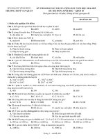
OPERATION AND MAINTENANCE OF OFFSHORE CRANES
Use Main Hoist: Tap fist on head,
then use regular signals.
Use Whip Line: (Auxiliary Hoist)
Tap elbow with one hand, and then
use regular signals.
Raise the Boom and Lower the
Load: With arm extended, thumb
pointing up, flex fingers in and out as
long as load movement is desired.
Articulating Boom Crane (with
hoist option) – Raise the boom tip
and lower the load
Extended Boom:
(Telescoping Booms) both
fists in front of body with
thumbs pointing outward.
Articulating Boom Crane –
Increase radius of Boom Tip
15
Lower the Boom and Raise the Load:
With arm extended, thumb pointing
down, flex fingers in and out as long as
load movement is desired.
Articulating Boom Crane (with Hoist
option) – Lower the boom tip and raise
the load
Retract Boom: (Telescoping Booms)
both fists in front of body with thumbs
pointing toward each other.
Articulating Boom Crane: Decrease
Radius of Boom Tip
Stop: Arms extended, palm
down, move arm back and
forth horizontally.
Figure 1 (continued)—Standard Hand Signals for Controlling Crane Operations
16
API RECOMMENDED PRACTICE 2D
4.7.2
Load Test Requirements
The following shall apply to load tests.
a)
The crane shall be operated during testing in accordance with Section 4.
b)
The crane shall be inspected in accordance with the annual inspection requirements before and after
each test. Attention should be given to rigging used to attach loads. Tag lines should be used on test
loads.
c)
The test weights or dynamometer should be verified for accuracy by a qualified inspector.
d)
All lifts should be planned in advance, taking into account the crane’s physical location, the available
space for staging and assembling the test loads, and the potentially hazardous areas to be avoided. See
7.3 for more information on planning the lift.
e)
When the test load is lifted the crane operator shall allow the control lever/s to return to the neutral
position. The load test should be held for a minimum of 5 minutes.
f)
When a dynamometer is used to verify the test weight(s) the weights shall be allowed to freely rotate in
order not to create a torsional stress in the dynamometer which can lead to inaccurate readings.
g)
Crane load indicators shall not be used to test cranes.
h)
Relief valves on hydraulic cranes should not be adjusted above manufacturer’s recommended pressures
and current limiting devices on electric cranes should not be bypassed or adjusted to increase available
hoist line pull. The test may be conducted with the highest load the hoist can lift as long as it is equal to
the rated load.
i)
Engine speed should not be adjusted above the manufacturer’s recommended maximum rated RPM.
j)
The test load for all lifts shall be based on crane rating chart, wire rope strength, available hoist line pull,
and number of parts of line. The static/onboard test load and the test radius should be calculated to load
the crane as shown in Table 1.
Table 1—Static/Onboard Test Load and Radius
Static/Onboard Rated Load at a
Specific Radius
lb (kg)
Test Loads in Excess of
Static/Onboard Rated Load at
a Specific Radius
≤ 40,000 (18,144)
25 %
> 40,000 ≤ 100,000
(>18,144 ≤ 45,356)
10,000 lb (4536 kg)
> 100,000 (45,356)
10 %
k)
All cranes should be tested as they are normally rigged. Cranes should not be rigged with extra parts of
line or have their hydraulic pressures, electric currents, or engine output increased. The load test should
not necessarily be based on the highest load shown on the rating chart.
l)
A live weight test shall be performed for initial and temporary installations and for relocated cranes as
follows:
—
load test weight/s shall be swung in all directions which the crane will be operated, avoiding
obstructions (e.g. derricks, living quarters, well heads, compressors, etc.) that are present;
OPERATION AND MAINTENANCE OF OFFSHORE CRANES
17
—
test load shall be raised and lowered to demonstrate the hoist will function properly and test the
static brakes;
—
when the hoist is the limiting factor the hoist shall lift the safe working load as a minimum (see
Figure D.2 for example).
m) Most recent Load test records should be maintained in crane records.
See Annex D for additional information on load testing.
4.8
Pull Test
A pull test may be conducted at the discretion of the crane owner or the crane owner representative.
When the crane owner or crane owner’s representative elects to have a crane pull tested, a calibrated
dynamometer or calibrated load cell attached to an engineered fixed point or a known suspended weight
should be used and the pull test should be held for a minimum of five minutes. Upon the completion of the
pull test, a qualified crane operator or qualified inspector should perform a pre-use inspection of the crane to
ensure no damage occurred during the test.
5
Inspection, Testing, and Maintenance
5.1
Usage and Inspection
5.1.1
General
Inspections are intended to identify all deficiencies or items, which would affect the safe operation or reduce
the lifting capability of the crane. Inspections should utilize methods and procedures appropriate for the
crane type and its past and anticipated usage, as determined by the crane owner.
Restricted service may, in some cases, be continued after the identification and before correction of a
deficiency. In such cases, it is the responsibility of the qualified crane operator or qualified inspector to
document the deficiency, reporting it to the crane owners. Based on this information, the crane owner should
define the appropriate restriction and post necessary cautionary notices, after consultation with the crane
manufacturer, authorized surveyor, certifying authority or other qualified source (such as an API 2C-licensed
crane manufacturer, or an engineer experienced in the design of the crane, as determined by the crane
owner).
Action taken to correct a deficiency should be made as soon as practicable.
5.1.2
5.1.2.1
Crane Usage Categories
General
Inspection procedures for cranes in-service are divided into three general categories based upon their usage
or duty cycle, which in turn determines different, appropriate intervals at which inspections are to be
performed. The usage categories should be assigned by the users on a consistent crane-by-crane basis.
The intent is to measure their duty cycle as the duration of time for which the crane is in actual use. See
Annex B for further information. The three crane usage categories are described in 5.2.1.2 through 5.1.2.4.
Special attention should be given to wire rope, condition, spooling and lubrication on these cranes during
pre-use inspections.
5.1.2.2
Infrequent Usage Production Duty Cycle
Infrequent usage applies to those cranes that are used for 10 hours or less per month, based on the
averaged use over a quarter. These cranes shall be subject to a pre-use inspection and an annual
inspection. However, if the crane sits idle for three months or more the crane shall be subject to a monthly