NT11S Programmable Terminal Operation Manual v029-e1-2
Bạn đang xem bản rút gọn của tài liệu. Xem và tải ngay bản đầy đủ của tài liệu tại đây (648.65 KB, 173 trang )
NT11S
Programmable Terminal
Operation Manual
Produced June 1997
iii
OMRON Product References
All OMRON products are capitalized in this manual. The word “Unit” is also capitalized when it refers to an
OMRON product, regardless of whether or not it appears in the proper name of the product.
The abbreviation “Ch,” which appears in some displays and on some OMRON products, often means
“word” and is abbreviated “Wd” in documentation in this sense.
The abbreviation “PC” means Programmable Controller and is not used as an abbreviation for anything
else.
The abbreviation “Host” means PC that controls NT11S.
Visual Aids
The following headings appear in the left column of the manual to help you locate different types of information.
Note
1, 2, 3...
Indicates information of particular interest for efficient and convenient operation
of the product.
1. Indicates lists of one sort or another, such as procedures, checklists, etc.
E OMRON, 1997
All rights reserved. No part of this publication may be reproduced, stored in a retrieval system, or transmitted, in any
form, or by any means, mechanical, electronic, photocopying, recording, or otherwise, without the prior written permission of OMRON.
No patent liability is assumed with respect to the use of the information contained herein. Moreover, because OMRON
is constantly striving to improve its high-quality products, the information contained in this manual is subject to change
without notice. Every precaution has been taken in the preparation of this manual. Nevertheless, OMRON assumes no
responsibility for errors or omissions. Neither is any liability assumed for damages resulting from the use of the information contained in this publication.
v
TABLE OF CONTENTS
PRECAUTIONS . . . . . . . . . . . . . . . . . . . . . . . . . . . . . . . . .
1
2
3
Intended Audience . . . . . . . . . . . . . . . . . . . . . . . . . . . . . . . . . . . . . . . . . . . . . . . . . . . . . . . . . . . xii
General Precautions . . . . . . . . . . . . . . . . . . . . . . . . . . . . . . . . . . . . . . . . . . . . . . . . . . . . . . . . . . xii
Safety Precautions . . . . . . . . . . . . . . . . . . . . . . . . . . . . . . . . . . . . . . . . . . . . . . . . . . . . . . . . . . . xii
SECTION 1
Functions of the NT11S . . . . . . . . . . . . . . . . . . . . . . . . . . . .
1-1
1-2
1-3
1-4
1-5
1-6
Getting Starting . . . . . . . . . . . . . . . . . . . . . . . . . . . . . . . . . . . . . . . . . . . . . . . . . . . . . . . .
Role and Operation of NT11S . . . . . . . . . . . . . . . . . . . . . . . . . . . . . . . . . . . . . . . . . . . . .
Functions of NT11S . . . . . . . . . . . . . . . . . . . . . . . . . . . . . . . . . . . . . . . . . . . . . . . . . . . . .
System Configuration . . . . . . . . . . . . . . . . . . . . . . . . . . . . . . . . . . . . . . . . . . . . . . . . . . .
Direct Connection Function . . . . . . . . . . . . . . . . . . . . . . . . . . . . . . . . . . . . . . . . . . . . . . .
Before Operating . . . . . . . . . . . . . . . . . . . . . . . . . . . . . . . . . . . . . . . . . . . . . . . . . . . . . . .
SECTION 2
Hardware Settings and Connections . . . . . . . . . . . . . . . . .
2-1
2-2
2-3
2-4
2-5
2-6
2-7
Description of Parts and Settings . . . . . . . . . . . . . . . . . . . . . . . . . . . . . . . . . . . . . . . . . . .
Installation . . . . . . . . . . . . . . . . . . . . . . . . . . . . . . . . . . . . . . . . . . . . . . . . . . . . . . . . . . . .
Connecting to the Support Tool . . . . . . . . . . . . . . . . . . . . . . . . . . . . . . . . . . . . . . . . . . . .
Connection to a PC by the Host Link (RS-232C Type) . . . . . . . . . . . . . . . . . . . . . . . . .
Connection to a PC by the Host Link (RS-422A Type) . . . . . . . . . . . . . . . . . . . . . . . . .
Connection to a PC by the NT Link . . . . . . . . . . . . . . . . . . . . . . . . . . . . . . . . . . . . . . . .
Connecting a Printer . . . . . . . . . . . . . . . . . . . . . . . . . . . . . . . . . . . . . . . . . . . . . . . . . . . .
SECTION 3
System Menu Operation . . . . . . . . . . . . . . . . . . . . . . . . . . .
3-1
3-2
3-3
3-4
3-5
3-6
3-7
Operation Flow by the System Menu . . . . . . . . . . . . . . . . . . . . . . . . . . . . . . . . . . . . . . .
Starting the NT11S . . . . . . . . . . . . . . . . . . . . . . . . . . . . . . . . . . . . . . . . . . . . . . . . . . . . .
Operation Modes and the System Menu . . . . . . . . . . . . . . . . . . . . . . . . . . . . . . . . . . . . .
Initializing Memory . . . . . . . . . . . . . . . . . . . . . . . . . . . . . . . . . . . . . . . . . . . . . . . . . . . . .
Transferring the System Program . . . . . . . . . . . . . . . . . . . . . . . . . . . . . . . . . . . . . . . . . .
Registering the Screen Data . . . . . . . . . . . . . . . . . . . . . . . . . . . . . . . . . . . . . . . . . . . . . .
Setting the Conditions of Communications with the PC
by Using the Memory Switches . . . . . . . . . . . . . . . . . . . . . . . . . . . . . . . . . . . . . . . . . . . .
3-8 Starting the Operation . . . . . . . . . . . . . . . . . . . . . . . . . . . . . . . . . . . . . . . . . . . . . . . . . . .
3-9 Backlight OFF . . . . . . . . . . . . . . . . . . . . . . . . . . . . . . . . . . . . . . . . . . . . . . . . . . . . . . . . .
3-10 System Maintenance . . . . . . . . . . . . . . . . . . . . . . . . . . . . . . . . . . . . . . . . . . . . . . . . . . . .
SECTION 4
NT11S Functions . . . . . . . . . . . . . . . . . . . . . . . . . . . . . . . . .
4-1
4-2
4-3
4-4
4-5
4-6
4-7
4-8
4-9
xi
Creating and Transmitting Screen Data . . . . . . . . . . . . . . . . . . . . . . . . . . . . . . . . . . . . .
Outline of Functions . . . . . . . . . . . . . . . . . . . . . . . . . . . . . . . . . . . . . . . . . . . . . . . . . . . .
Screen Display . . . . . . . . . . . . . . . . . . . . . . . . . . . . . . . . . . . . . . . . . . . . . . . . . . . . . . . . .
Memory Tables . . . . . . . . . . . . . . . . . . . . . . . . . . . . . . . . . . . . . . . . . . . . . . . . . . . . . . . .
Bar Graphs . . . . . . . . . . . . . . . . . . . . . . . . . . . . . . . . . . . . . . . . . . . . . . . . . . . . . . . . . . . .
Numeral Setting . . . . . . . . . . . . . . . . . . . . . . . . . . . . . . . . . . . . . . . . . . . . . . . . . . . . . . . .
Menu Screen Function . . . . . . . . . . . . . . . . . . . . . . . . . . . . . . . . . . . . . . . . . . . . . . . . . . .
Password Screen Display Function . . . . . . . . . . . . . . . . . . . . . . . . . . . . . . . . . . . . . . . . .
Display History Screen Function . . . . . . . . . . . . . . . . . . . . . . . . . . . . . . . . . . . . . . . . . . .
1
2
3
5
9
10
15
17
18
22
25
26
31
37
39
41
42
43
44
48
51
54
57
62
63
65
71
72
77
80
81
83
85
87
88
90
vii
4-10 Daily Report/Display History Printing Function . . . . . . . . . . . . . . . . . . . . . . . . . . . . . . .
SECTION 5
Using Host Link/NT Link . . . . . . . . . . . . . . . . . . . . . . . . . .
5-1
5-2
5-3
5-4
5-5
Outline of Host Link / NT Link Operation . . . . . . . . . . . . . . . . . . . . . . . . . . . . . . . . . . .
Memory Tables and Bar Graph . . . . . . . . . . . . . . . . . . . . . . . . . . . . . . . . . . . . . . . . . . . .
Numeral Setting . . . . . . . . . . . . . . . . . . . . . . . . . . . . . . . . . . . . . . . . . . . . . . . . . . . . . . . .
NT11S Status Control . . . . . . . . . . . . . . . . . . . . . . . . . . . . . . . . . . . . . . . . . . . . . . . . . . .
Notification of the Operating Status to the PC
(Determining the NT11S Operating Status) . . . . . . . . . . . . . . . . . . . . . . . . . . . . . . . . . .
91
95
96
106
119
122
126
SECTION 6
Troubleshooting and Maintenance . . . . . . . . . . . . . . . . . . . 131
6-1
6-2
6-3
Hardware Faults . . . . . . . . . . . . . . . . . . . . . . . . . . . . . . . . . . . . . . . . . . . . . . . . . . . . . . . .
Responding to Displayed Error Messages . . . . . . . . . . . . . . . . . . . . . . . . . . . . . . . . . . . .
Inspection and Cleaning . . . . . . . . . . . . . . . . . . . . . . . . . . . . . . . . . . . . . . . . . . . . . . . . .
132
133
137
APPENDICES . . . . . . . . . . . . . . . . . . . . . . . . . . . . . . . . . . . 139
A. Specifications . . . . . . . . . . . . . . . . . . . . . . . . . . . . . . . . . . . . . . . . . . . . . . . . . . . . . . . . . . . .
139
B. Dimensions . . . . . . . . . . . . . . . . . . . . . . . . . . . . . . . . . . . . . . . . . . . . . . . . . . . . . . . . . . . . . .
144
C. NT11S Installation Environment . . . . . . . . . . . . . . . . . . . . . . . . . . . . . . . . . . . . . . . . . . . . .
145
D. Method for Making the Cable for Connection to the PC . . . . . . . . . . . . . . . . . . . . . . . . . .
146
E. Making the Cable for Connection to the Support Tool . . . . . . . . . . . . . . . . . . . . . . . . . . . .
155
F. NT11S Internal Processing . . . . . . . . . . . . . . . . . . . . . . . . . . . . . . . . . . . . . . . . . . . . . . . . . .
156
G. Model List . . . . . . . . . . . . . . . . . . . . . . . . . . . . . . . . . . . . . . . . . . . . . . . . . . . . . . . . . . . . . .
158
H. PC Memory Map . . . . . . . . . . . . . . . . . . . . . . . . . . . . . . . . . . . . . . . . . . . . . . . . . . . . . . . . .
160
I.
161
Special Characters . . . . . . . . . . . . . . . . . . . . . . . . . . . . . . . . . . . . . . . . . . . . . . . . . . . . . . . .
INDEX . . . . . . . . . . . . . . . . . . . . . . . . . . . . . . . . . . . . . . . . . 163
viii
About this Manual:
This manual describes the basic functions and operation procedures of the NT-series programmable terminal NT11S, its operations when connected to a PC, and includes the sections described below.
Please read this manual carefully and be sure you understand the information provided before attempting
to install and operate the NT-series programmable terminal NT11S.
Section 1 describes the operation functions, system configuration, and the direct connection function of
the NT11S.
Section 2 describes the hardware settings, installation to an operation panel, connection to optional devices and PC.
Section 3 describes the operation of the System Menu and the maintenance of the NT11S.
Section 4 describes the functions of the NT11S when it is connected to a PC.
Section 5 describes how to use the NT11S when it is connected to the PC using the host link or NT link.
Section 6 describes the procedures to follow when the NT11S does not operate correctly.
APPENDIX describes the specifications and the method for making connecting cables, and includes an
area list for the PC.
ix
Related Manuals and Their Contents:
The related manuals are listed below.
The S symbol at the end of the manual number is the revision history symbol.
[Operating the programmable terminal and communicating with the host]
D NT11S Programmable Terminal Operation Manual (V029-E1-S )
. . . . . . . . . . . . . . . . . . . . . . . . . . . . . . . . . . . . . . . . . . . . . . . . . . . . . . . This manual
This operation manual is the manual for the NT11S itself.
The NT11S is a unit which integrates a programmable terminal body. This operation manual describes the functions and handling of the programmable terminal
body.
[Creating and transferring screen data]
D NT-series NT11S Support Tool Operation Manual (V030-E1-S )
The screens displayed on the NT11S are created with the support tool and transferred to the NT11S. This manual describes how to create and transfer screen
data.
x
PRECAUTIONS
This section provides general precautions for using the Programmable Terminal.
The information contained in this section is important for the safe and reliable application of the Programmable
Terminal. You must read this section and understand the information contained before attempting to set up or operate a Programmable Terminal.
1
2
3
Intended Audience . . . . . . . . . . . . . . . . . . . . . . . . . . . . . . . . . . . . . . . . . . . . . . . . . . . . . . . . . . .
General Precautions . . . . . . . . . . . . . . . . . . . . . . . . . . . . . . . . . . . . . . . . . . . . . . . . . . . . . . . . . .
Safety Precautions . . . . . . . . . . . . . . . . . . . . . . . . . . . . . . . . . . . . . . . . . . . . . . . . . . . . . . . . . . . .
xii
xii
xii
xi
Safety Precautions
1
Intended Audience
This manual is intended for the following personnel, who must also have knowledge of electrical systems (an electrical engineer or the equivalent).
D Personnel in charge of installing FA systems.
D Personnel in charge of designing FA systems.
D Personnel in charge of managing FA systems and facilities.
2
General Precautions
The user must operate the product according to the performance specifications
described in the operation manuals.
Before using the product under conditions which are not desctibed in the manual
or applying the product to nuclear control systems, railroad systems, aviation
systems, vehicles, combustion systems, medical equipment, amusement machines, safety equipment, and other systems, machines, and equipment that
may have a serious influence on lives and property if used improperly, consult
your OMRON representative.
Make sure that the ratings and performance characteristics of the product are
sufficient for the systems, machines, and equipment, and be sure to provide the
systems, machines, and equipment with double safety mechanisms.
This manual provides information for using the Programmable Terminal. Be sure
to read this manual before attempting to use the software and keep this manual
close at hand for reference during operation.
WARNING It is extremely important that Programmable Terminals and related devices be
used for the specified purpose and under the specified conditions, especially in
applications that can directly or indirectly affect human life. You must consult with
your OMRON representative before applying Programmable Terminals to the
abovementioned applications.
WARNING Do not use input functions such as PT touch switches for applications where danger to human life or serious damage is possible, or for emergency switch applications.
3
Safety Precautions
Read these safety precautions carefully and make sure you understand them before using the Programmable Terminal so that you can use it safely and correctly.
Safety Conventions and
their Meanings
DANGER!
This operation manual uses the following conventions and symbols to indicate
cautions, warnings, and dangers in order to ensure safe use of the PT. The cautions, warnings, and dangers shown here contain important information related
to safety. The instructions in these cautions, warnings, and dangers must be
observed.
The conventions used and their meanings are presented below.
Indicates information that, if not heeded, is likely to result in loss of life or serious
injury.
WARNING Indicates information that, if not heeded, could possibly result in loss of life or serious injury.
CAUTION
xii
Indicates information that, if not heeded, could result in relatively serious or minor
injury, damage to the product, or faulty operation.
CAUTION
D Do not use input functions such as PT function keys for applications where danger to human life or serious property damage is possible, or as the emergency
stop switch.
D On unpacking the unit, check its external appearance and confirm that there is
no damage. Also confirm that there is no abnormal noise on shaking the unit
lightly. The product may malfunction if it is damaged.
D The thickness of applicable operation panel is 1.6 mm to 4.8 mm. All futtings
must be tightened uniformly to a torque of 0.5 to 0.6 N@m in order to ensure
water- and dust- resistence. The panel must not be soiled or warped, and must
be able to support an installation that will remain secure and strong.
D During work at the panel, take care to ensure that no metal scraps enter the
unit. Otherwise, the product may malfunction.
D Carefully check the wiring before switching ON the power.
D Do not connect AC power to the DC terminals.
D Use DC power supplies with low voltage and frequency fluctuations.
D For the connection to the power supply terminal block, twisted wires of 2 mm2
or greater cross sectional area and M 3.5 size crimp terminals must be used.
Tighten the screws on the terminal block to a torque of 0.5 N@m.
Otherwise fire may occur.
D After connecting a communication cable, always secure it with the screws.
Otherwise the cable may disconnect, causing operation to fail.
D The cable’s tensile load is 30 N. Do not subject it to loads greater than this.
Otherwise a discontinuity may occur, causing operation to fail.
D Switch off the NT11S power supply before connecting or disconnecting a connector.
D If the connection cable is connected or disconnected while the power of the
printer is on, the NT11S may malfunction. Make sure to turn off the power of the
printer before connecting or disconnecting the connection cable.
D In addition to the DIP switches, set also the “Comm. Method”, “Host Link
Speed”, “Auto-restart”, etc. at the memory switches. For these settings, refer to
Section 3-7 “Setting the Conditions of Communications with the PC by Using
the Memory Switches” (page 57)
D After changing the switch settings, always press the reset switch or turn the
power off and back on.
Otherwise the system will not operate as expected.
D Confirm system safety before turning the power ON/OFF or resetting.
Otherwise the system may operate unpredictably.
D Carefully check the operation of all screen data and host programs before using them. If incorrect, the system may operate unpredictably.
Otherwise the system may operate unpredictably.
D After images may remain if the same pattern is displayed for a long period.
To prevent the formation of an afterimage, either use the screen saver function
or periodicaly switch screens.
xiii
D Do not disassemble for repairs or modification. Otherwise, the product may
malfunction.
D The disposal of the unit may be regulated by nationl or local authorities. Dispose of them in accordance with the laws and regulations of the relevant country and local authority.
D Set so that there is no overlap between the PT status control area and PT status notify area. Otherwise the system may operate unpredictably.
xiv
SECTION 1
Functions of the NT11S
NT11S is a new programmable terminal (PT) which incorporates a host interface unit in a programmable terminal body. It can
be easily installed and used.
This section gives the operation examples and characteristics of the NT11S so that you will understand the applications of the
NT11S.
1-1
1-2
1-3
1-4
1-5
1-6
Getting Starting . . . . . . . . . . . . . . . . . . . . . . . . . . . . . . . . . . . . . . . . . . . . . . . . . . . . . . . . . . . . . .
Role and Operation of NT11S . . . . . . . . . . . . . . . . . . . . . . . . . . . . . . . . . . . . . . . . . . . . . . . . . . .
1-2-1 Operations of NT11S . . . . . . . . . . . . . . . . . . . . . . . . . . . . . . . . . . . . . . . . . . . . . . . . . . . .
Functions of NT11S . . . . . . . . . . . . . . . . . . . . . . . . . . . . . . . . . . . . . . . . . . . . . . . . . . . . . . . . . .
1-3-1 Features . . . . . . . . . . . . . . . . . . . . . . . . . . . . . . . . . . . . . . . . . . . . . . . . . . . . . . . . . . . . . .
1-3-2 Principal Functions of NT11S . . . . . . . . . . . . . . . . . . . . . . . . . . . . . . . . . . . . . . . . . . . . .
1-3-3 Displays . . . . . . . . . . . . . . . . . . . . . . . . . . . . . . . . . . . . . . . . . . . . . . . . . . . . . . . . . . . . . .
1-3-4 System Keys . . . . . . . . . . . . . . . . . . . . . . . . . . . . . . . . . . . . . . . . . . . . . . . . . . . . . . . . . . .
System Configuration . . . . . . . . . . . . . . . . . . . . . . . . . . . . . . . . . . . . . . . . . . . . . . . . . . . . . . . . .
Direct Connection Function . . . . . . . . . . . . . . . . . . . . . . . . . . . . . . . . . . . . . . . . . . . . . . . . . . . .
1-5-1 NT Link . . . . . . . . . . . . . . . . . . . . . . . . . . . . . . . . . . . . . . . . . . . . . . . . . . . . . . . . . . . . . .
1-5-2 Functions of the Allocated Bits and Words . . . . . . . . . . . . . . . . . . . . . . . . . . . . . . . . . . .
Before Operating . . . . . . . . . . . . . . . . . . . . . . . . . . . . . . . . . . . . . . . . . . . . . . . . . . . . . . . . . . . . .
2
3
4
5
5
6
7
8
9
10
11
12
15
1
Getting Starting
1-1
Section 1-1
Getting Starting
To ensure that the NT11S works correctly, carefully observe the following when
installing and handling it.
Location
Do not install the NT11S in a location subject to the following conditions;
S Near a computer, radio transmitter or receiver, etc.
S Dust, chemicals, or steam
S Severe temperature fluctuations
S High humidity and condensation
S Strong electrical or magnetic fields
S Poor ventilation
S Severe vibration
Handling
Do not;
S Subject the NT11S to strong shocks or vibrations
S Put heavy objects on the NT11S
S Supply a voltage different from the specified voltage
S Disassemble or modify the NT11S
Cautions on Cleaning
To clean the front panel, use a soft, dry cloth. If it is very dirty, use diluted (2%)
neutral detergent.
Do not use volatile solvents such as benzene, thinner, or a chemically treated
cloth. Their use will cause deformation or discoloration.
Cautions on Afterimage
If the same screen contents are kept displayed for a long time, an afterimage may
occur. To prevent this problem, either set the afterimage prevention function or
make a program which periodically changes the displayed screen.
Cautions on Operating the System Keys
Do not operate the system keys with sharply pointed objects, such as your fingernails or a screwdriver.
This could break the film.
2
Role and Operation of NT11S
1-2
Section 1-2
Role and Operation of NT11S
NT11S is a programmable terminal used to display and transmit the information in
an FA site. The following gives a general description of the role and operation of
the NT11S for those who use a programmable terminal (PT) for the first time.
Production Line Status Monitoring
The NT11S displays real-time information about the system and equipment operating status, etc.
Line 1 Status
Machine:NT11S-ST121
Product: 137 units
75%
Messages
The NT11S warns of system or equipment failures and prompts the appropriate
remedial action.
Assembly line B
Positioning pin
Panel Switch Functions
The NT11S can be used in place of external data input equipment such as an operation panel, to transmit data to a PC.
Positioning
X-AXIS
100 point
Y-AXIS
150 point
Z-AXIS
80 point
3
Role and Operation of NT11S
1-2-1
Section 1-2
Operations of NT11S
Displays Screens
The information to be displayed (screen data) can be created on a computer by
using support tools and stored in the NT11S. The screen data can be displayed on
the NT11S in response to the instructions from a PC or system keys operation.
PC
The screen data designated by
instructions from PC or System
keys operation is displayed.
Receives Data from a PC
NT11S can be connected to a PC by a host link or NT link and receive necessary
data from the PC.
Host link, NT link
PC
OMRON’s PC
Sends Data to a PC
Data input through a numeric key can be sent to a PC.
Numeric key
PC
ON/OFF information,
numeric data, etc.
Screen Data
The screen data to be displayed on the NT11S can be created by a computer by
using support tools. Connect the NT11S to a PC/AT with an RS-232C cable so that
the screen data are transferred to the NT11S.
Create screen data.
RSĆ232C
PC/AT
(support tools)
Screen data
This connection is made only to
transmit the screen data by using
NT11S and tools.
4
Functions of NT11S
1-3
Section 1-3
Functions of NT11S
The NT11S has the following features and functions;
1-3-1
Features
Downsized Body
S The NT11S has the thinnest depth (31 mm or less in the panel) in the NT series.
S It is very compact, with a width of 218 mm and a height of 113 mm.
S Features three ports: for RS-232C, RS-422A, and printer output.
S The tool connectors and the PC communication connectors are used in common.
Construction Best Suited to the FA Environment
S Easy-to-read screen even in direct sunlight.
S Waterproofed to a standard equivalent to IP65 and NEMA4.
160 dots
64 dots
Wide angle of visibility "35_
A Host I/F Unit, Screen Data Memory, and a system program transfer ROM are All Incorporated
S There is no complicated installation work except a simple connection to a PC.
S A flash memory is used for the screen data memory. There is no need of backup
battery.
S A host link (direct), and an NT link are standard equipment.
5
Functions of NT11S
1-3-2
Section 1-3
Principal Functions of NT11S
Functions Related to the Data Display
S Character display
Characters of standard and double-width can be displayed. Characters can flash or be highlighted.
S Memory data display
Contents of the character-string memory table and the numeral memory table can be displayed.
The memory table contents can be changed from the PC.
S Bar graph display
Bar graphs corresponding to the contents of the numeral table can be displayed.
Functions Related to the Data Input
S Input by the system key
Data can be input, and the displayed screen changed,
by using the numeric keys, function keys, and arrow
keys on the panel of the NT11S.
S Numeric setting function
The numeric values can be input at the operation site by
the system key and sent to the PC.
Other Functions
S Communications with a PC
The host link, NT link is used to connect to a PC for data communication.
S System function
The system setting and maintenance can be executed by using the System
Menu on the screen.
S Screen data creation
The screen data can be created by using support tools on the computer and
stored in the unit.
6
Functions of NT11S
1-3-3
Section 1-3
Displays
The NT11S can display elements such as characters, numeric value, and bar
graphs on a screen. The screen data displayed on the NT11S are created by using
support tools on a computer.
Characters
(character string)
Characters (text)
Bar graph
Characters (text)
Line 1 Status
Machine:NT11S-ST121
Product:137 units
75%
Numeric value
(Numeral table)
Characters and marks which do not need to be changed can be written directly to
the screen.
Characters (character-string memory table)
Character-strings stored in the character-string memory table are displayed. The
display characters can be changed by changing the data stored in the characterstring memory table.
Numeric Values (numeral memory tables)
Numbers stored in the numeral memory table are displayed. The display numbers
can be changed by changing the data stored in the numeral table. Hexadecimal
values can also be displayed.
Bar Graphs
The bar graph extends and contracts in proportion to the data stored in the numeral memory table. A percentage value can also be displayed simultaneously.
Marks
Marks can be designed, created, and handled like characters by the user.
7
Functions of NT11S
1-3-4
Section 1-3
System Keys
The NT11S has system keys on its panel for input functions.
The system keys are used for inputting numerical values and for notifications to
the PC.
The system keys can be classified into the three types shown below.
- Numeric keys
- Arrow keys
- Function keys
NT11S
Screen display
Function keys
Numeric keys
Arrow keys
S Numeric keys
These are the numeral keys from [0] to [9], the decimal point key [.], the sign key
[+/–], the [CLR] key and the [ENTER] key. These keys are used for inputting numerical values.
S Arrow keys
Used to select the required numerical value input field when there is more than
one on the screen.
S Function keys
Used for notifications from the NT11S to the PC.
Also used to switch between the RUN mode and the system menu when the
power is switched on.
Caution Do not use input functions such as PT function keys for applications where danger
to human life or serious property damage is possible, or as the emergency stop
switch.
8
System Configuration
1-4
Section 1-4
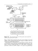
System Configuration
This section gives the basic configuration of a system which uses an NT11S. Use
an RS-232C cable to connect to a PC. Refer to the manual for individual device for
information on the equipment other than the NT11S in the system.
OMRON’s PC
Controls NT11S as required while controlling machines and
monitoring the production line.
Host link:
CQM1, C200H(S) series PC
CQM1, C200HS series: NT11S can be connected
directly to the CPU unit.
Note that C200H requires a host link unit.
NT link:
CQM1, C200H(S) series PC
CQM1 can be used with CPU41/42/43/44-E.
C200HS can be used with CPU21/23/31/33-E.
RS-232C cable
(for host link)
(Max. 15 m)
or RS-422A cable
(for host link)
(Max. 500 m)
Support tool
NT11S
Computer (support tool)
Gives displays of production line
monitoring and instructions to the
operation site and notifies the
switch ON/OFF status and
numeric value inputs to the PC.
Connected to NT11S as required and used to transfer the
NT11S screens and make settings for the NT11S.
Computer:
IBM PC/AT or compatible (IBM PC DOS Ver.5 or
later)
Support tool: NT11S support tool type NT11S-ZA3AT-EV1
Printer
Prints daily reports and
display histories.
Printer: ESC/P compatible
Reference The following two communication methods are supported for communications between the NT11S and PC: host link, and NT link. For the setting procedure, refer to
Section 3-7 Setting the Conditions of Communications with the PC by Using the
Memory Switches (page 57). It is impossible to connect a personal computer used
to drive the support tool and a PC at the same time.
9
Direct Connection Function
1-5
Section 1-5
Direct Connection Function
The communication method applied between the NT11S and the PC is either a
host link or NT link.
The NT11S can be used to refer to the contents necessary for the display information or to allocate the bits and words used for storing the input data to any area in
the PC. The NT11S can directly write and read such allocated bits and words so as
to change the display elements, control the operating status, and notify the status.
This function is called the “direct connection function”. The NT11S is designed exclusively for use with the direct connection.
The bits and words allocated by the direct connection function are called “allocated
bit” and “allocated word” respectively.
This function allows to read the information to be displayed on the NT11S from the
memory area in the PC and to write it to the memory table in the NT11S. Also, the
data input on the NT11S can be written to the PC’s memory area. The NT11S
screen status can be switched according to the PC’s memory area, and the
NT11S’s status data can be written to the PC’s memory area.
NT11S
PC
Data memory area
Internal relay area
Auxiliary relay area
Timer/counter
Features of the Direct Connection Function
S The bits and words referring to operating status and work instruction information
and those for storing input data can be freely allocated to almost any part of the
PC memory. Bits and words in the PC can be referenced from any memory table.
S The NT11S can directly refer to PC bit and word data so that it can be connected
to a PC without changing the PC program which controls currently running production line.
S The area to control and notify the NT11S status, including display screens, ON/
OFF of the backlight, and printing of daily reports and display histories, can be
freely allocated to any part of the PC memory.
The direct connection function allows the NT11S to directly read and write almost
all bits and words in the PC and to automatically change the NT11S screen display.
This function can reduce the load on the PC so that the program development efficiency of the PC improves.
10
Direct Connection Function
1-5-1
Section 1-5
NT Link
The NT link is a new communication method applied between the NT11S and a
PC.
The NT link uses the direct connection function and can execute high speed communications with a CPU (built-in NT link) of the CQM1, and C200HS.
Features of the NT Link
S High speed communications with specific types of PCs can be executed.
S Writing in units of bits to the PC memory area is possible. (*)
S This can be used even when the PC is in the RUN mode.
(*) Except a DM area.
The NT link is compatible with the host link. The NT11S screen data and the PC
programs handled by the host link direct connection can be used with for the NT
link as they are.
11
Direct Connection Function
1-5-2
Section 1-5
Functions of the Allocated Bits and Words
Elements displayed on the NT11S and the NT11S status can be allocated to the
bits and words of the PC. By changing the contents of the bits and words, the
NT11S can be controlled by the PC. It is also possible to send data to the PC by
pressing the function keys on the panel of the NT11S.
S Controlling the NT11S by a PC
The following NT11S functions can be controlled by a PC.
Screens
: Display of designated screens, confirmation of screen numbers, etc.
Memory tables
: Writing to a memory table, copying from a memory table to
another memory table, etc.
System control
: ON/OFF of backlight, control of output of daily reports and
display histories at a printer.
S Notifying from the NT11S to a PC
Data in the NT11S is sent to a PC when a numeric key is pressed. The following
types of data are sent to a PC.
- NT11S status
- Password input status
- Numeric values input by the numeral keys
- Function key input status
12
Direct Connection Function
Section 1-5
Functions of Display Elements
S Numeral memory table
Allocation destination: Word
Numeral memory
table 1 (TIM003)
NT11S
PC
Numeral memory table 150 (0005CH)
Allocate numeral memory tables to arbitrary words in the PC. If word contents
change when corresponding numeral memory table is displayed on the screen,
the value on the screen will also change. Monitoring of words can also be made
easily.
Reading and writing are executed so that the contents of allocated words are
always the same as those of the numeral memory tables.
S Character-string memory table
Allocation destination: Word
NT11S
PC
(“a”, “b”)
(“c”, “d”)
(“e”, “f”)
Character-string memory table 1
Allocated word number: 3ch
First word: DM0100
Allocate character-string memory tables to arbitrary words in the PC. If word
contents change when corresponding character-string memory table is displayed on the screen, the value on the screen will also change. Messages can be
displayed easily.
Reading and writing are executed so that the contents of allocated words are
always the same as those of the character-string memory tables.
13
Direct Connection Function
Section 1-5
Functions of the PT Status Control Area (PC to NT11S)
The “PT status control area” is used to control the NT11S status. When data is
written to this area in the PC, the NT11S reads the contents and operates according to the contents.
[Example of the PT status control area application]
When data is written to the PT status control area, the NT11S will operate as given
below.
Screen 3
display
NT11S
PC
PT status control area
0003
0050
1007
8010
Screen switch setting
Memory table
Copy setting
PT status control bits
Numeral memory table 50
Copy
Numeral memory table 7
Printing of daily reports or display histories
Functions of the PT Status Notify Area (NT11S to PC)
The “PT status notify area” is used to notify the changes of the NT11S status.
When a change is made in the NT11S status, the change is written to this area in
the PC. By reading the data from the area, the NT11S status can be checked.
[Example of the PT status notify area application]
When a change is made in the NT11S status, such change will be notified to the PT
status notify area as mentioned below.
NT11S
12345678
PC
Numeral memory table 13
PT status notify area
12345678
Currently display screen
Content update memory table
PT status
Allocated word (numeral table 13)
12345678
14
Start
Start + 1
Before Operating
1-6
Section 1-6
Before Operating
Follow the procedure given below to start the system of the NT11S.
PC
Check and change the
PC settings.
S For the host link, refer
to page 26 and the
manuals for the host
link unit and peripheral
tools.
S For the NT link, refer
to page 37.
NT11S
Support tool
Set the DIP switches.
(page 20)
Install to the operation
panel.
(page 22)
Connect the power supply.
(page 23)
Connect to the NT11S.
Connect to the PC.
Install the support tool
in the computer.
S (Host link: page 26)
S (NT link: page 37)
Check the settings and
communications.
Create the PC program.
Transfer the
screen data.
(page 54)
Transfer the system
program by using the
system transfer tool.
Create the screens.
(refer to Section 4 and the
manuals for the support tools)
Start operation.
Reference Use support tool NT11S Support Tool (type NT11S-ZA3AT-EV1).
Refer to the following manuals for the equipment and software.
Equipment or Software
Manual Title
Manual Number
Support tools
NT-series NT11S Support Tool Operation Manual
V030-E1-j
PCs
SYSMAC C200H Operation Manual
W130-E1-j
SYSMAC C200HS Operation Manual
W235-E1-j
SYSMAC CQM1-CPM1 Programming Manual
W228-E1-j
SYSMAC C Series Host Link Unit User’s Manual
W143-E1-j
Host link Unit
15