Iec 60747 15 2010
Bạn đang xem bản rút gọn của tài liệu. Xem và tải ngay bản đầy đủ của tài liệu tại đây (455.73 KB, 54 trang )
®
Edition 2.0 2010-12
INTERNATIONAL
STANDARD
NORME
INTERNATIONALE
Semiconductor devices – Discrete devices –
Part 15: Isolated power semiconductor devices
IEC 60747-15:2010
Dispositifs à semiconducteurs – Dispositifs discrets –
Partie 15: Dispositifs de puissance à semiconducteurs isolés
Copyrighted material licensed to BR Demo by Thomson Reuters (Scientific), Inc., subscriptions.techstreet.com, downloaded on Nov-28-2014 by James Madison. No further reproduction or distribution is permitted. Uncontrolled when printe
IEC 60747-15
All rights reserved. Unless otherwise specified, no part of this publication may be reproduced or utilized in any form or by
any means, electronic or mechanical, including photocopying and microfilm, without permission in writing from either IEC or
IEC's member National Committee in the country of the requester.
If you have any questions about IEC copyright or have an enquiry about obtaining additional rights to this publication,
please contact the address below or your local IEC member National Committee for further information.
Droits de reproduction réservés. Sauf indication contraire, aucune partie de cette publication ne peut être reproduite
ni utilisée sous quelque forme que ce soit et par aucun procédé, électronique ou mécanique, y compris la photocopie
et les microfilms, sans l'accord écrit de la CEI ou du Comité national de la CEI du pays du demandeur.
Si vous avez des questions sur le copyright de la CEI ou si vous désirez obtenir des droits supplémentaires sur cette
publication, utilisez les coordonnées ci-après ou contactez le Comité national de la CEI de votre pays de résidence.
IEC Central Office
3, rue de Varembé
CH-1211 Geneva 20
Switzerland
Email:
W eb: www.iec.ch
About the IEC
The International Electrotechnical Commission (IEC) is the leading global organization that prepares and publishes
International Standards for all electrical, electronic and related technologies.
About IEC publications
The technical content of IEC publications is kept under constant review by the IEC. Please make sure that you have the
latest edition, a corrigenda or an amendment might have been published.
§ Catalogue of IEC publications: www.iec.ch/searchpub
The IEC on-line Catalogue enables you to search by a variety of criteria (reference number, text, technical committee,…).
It also gives information on projects, withdrawn and replaced publications.
§ IEC Just Published: www.iec.ch/online_news/justpub
Stay up to date on all new IEC publications. Just Published details twice a month all new publications released. Available
on-line and also by email.
§ Electropedia: www.electropedia.org
The world's leading online dictionary of electronic and electrical terms containing more than 20 000 terms and definitions
in English and French, with equivalent terms in additional languages. Also known as the International Electrotechnical
Vocabulary online.
§ Customer Service Centre: www.iec.ch/webstore/custserv
If you wish to give us your feedback on this publication or need further assistance, please visit the Customer Service
Centre FAQ or contact us:
Email:
Tel.: +41 22 919 02 11
Fax: +41 22 919 03 00
A propos de la CEI
La Commission Electrotechnique Internationale (CEI) est la première organisation mondiale qui élabore et publie des
normes internationales pour tout ce qui a trait à l'électricité, à l'électronique et aux technologies apparentées.
A propos des publications CEI
Le contenu technique des publications de la CEI est constamment revu. Veuillez vous assurer que vous possédez
l’édition la plus récente, un corrigendum ou amendement peut avoir été publié.
§ Catalogue des publications de la CEI: www.iec.ch/searchpub/cur_fut-f.htm
Le Catalogue en-ligne de la CEI vous permet d’effectuer des recherches en utilisant différents critères (numéro de référence,
texte, comité d’études,…). Il donne aussi des informations sur les projets et les publications retirées ou remplacées.
§ Just Published CEI: www.iec.ch/online_news/justpub
Restez informé sur les nouvelles publications de la CEI. Just Published détaille deux fois par mois les nouvelles
publications parues. Disponible en-ligne et aussi par email.
§ Electropedia: www.electropedia.org
Le premier dictionnaire en ligne au monde de termes électroniques et électriques. Il contient plus de 20 000 termes et
définitions en anglais et en franỗais, ainsi que les termes ộquivalents dans les langues additionnelles. Egalement appelé
Vocabulaire Electrotechnique International en ligne.
§ Service Clients: www.iec.ch/webstore/custserv/custserv_entry-f.htm
Si vous désirez nous donner des commentaires sur cette publication ou si vous avez des questions, visitez le FAQ du
Service clients ou contactez-nous:
Email:
Tél.: +41 22 919 02 11
Fax: +41 22 919 03 00
Copyrighted material licensed to BR Demo by Thomson Reuters (Scientific), Inc., subscriptions.techstreet.com, downloaded on Nov-28-2014 by James Madison. No further reproduction or distribution is permitted. Uncontrolled when printe
THIS PUBLICATION IS COPYRIGHT PROTECTED
Copyright © 2010 IEC, Geneva, Switzerland
®
Edition 2.0 2010-12
INTERNATIONAL
STANDARD
NORME
INTERNATIONALE
Semiconductor devices – Discrete devices –
Part 15: Isolated power semiconductor devices
Dispositifs à semiconducteurs – Dispositifs discrets –
Partie 15: Dispositifs de puissance à semiconducteurs isolés
INTERNATIONAL
ELECTROTECHNICAL
COMMISSION
COMMISSION
ELECTROTECHNIQUE
INTERNATIONALE
PRICE CODE
CODE PRIX
ICS 31.080.99
® Registered trademark of the International Electrotechnical Commission
Marque déposée de la Commission Electrotechnique Internationale
T
ISBN 978-2-88912-310-0
Copyrighted material licensed to BR Demo by Thomson Reuters (Scientific), Inc., subscriptions.techstreet.com, downloaded on Nov-28-2014 by James Madison. No further reproduction or distribution is permitted. Uncontrolled when printe
IEC 60747-15
60747-15 Ó IEC:2010
CONTENTS
FOREWORD .................................................................................................................. 4
1
Scope ...................................................................................................................... 6
2
Normative references ................................................................................................ 6
3
Terms and definitions ................................................................................................ 7
4
Letter symbols .......................................................................................................... 8
4.1
4.2
4.3
5
General ........................................................................................................... 8
Additional subscripts/symbols ............................................................................ 8
List letter symbols ............................................................................................ 8
4.3.1 Voltages and currents ............................................................................ 8
4.3.2 Mechanical symbols .............................................................................. 8
4.3.3 Other symbols ...................................................................................... 9
Essential ratings (limiting values) and characteristics ................................................... 9
5.1
5.2
6
General ........................................................................................................... 9
Ratings (limiting values).................................................................................... 9
5.2.1 Isolation voltage (V isol ) .......................................................................... 9
5.2.2 Peak case non-rupture current (I RSMC or I CNR ) (where appropriate)............ 9
5.2.3 Terminal current (I tRMS) (where appropriate), ........................................... 9
5.2.4 Total power dissipation (P tot ) .................................................................. 9
5.2.5 Temperatures ....................................................................................... 9
5.2.6 Mechanical ratings .............................................................................. 10
5.2.7 Climatic ratings (where appropriate) ...................................................... 10
5.3 Characteristics ............................................................................................... 10
5.3.1 Mechanical characteristics ................................................................... 10
5.3.2 Parasitic inductance (L p) ...................................................................... 11
5.3.3 Parasitic capacitances (C p) .................................................................. 11
5.3.4 Partial discharge inception voltage (V iM or V i(RMS) ) (where
appropriate) ........................................................................................ 11
5.3.5 Partial discharge extinction voltage (V eM or V e(RMS) ) (where
appropriate) ........................................................................................ 11
5.3.6 Thermal resistances ............................................................................ 11
5.3.7 Transient thermal impedance (Z th ) ........................................................ 12
Measurement methods ............................................................................................ 12
6.1
7
Verification of isolation voltage rating between terminals and base plate
(V isol ) ............................................................................................................ 12
6.2 Methods of measurement ................................................................................ 13
6.2.1 Partial discharge inception and extinction voltages (V i ) (V e) .................... 13
6.2.2 Parasitic inductance (L p ) ...................................................................... 13
6.2.3 Parasitic capacitance terminal to case (C p ) ............................................ 15
6.2.4 Thermal characteristics ........................................................................ 16
Acceptance and reliability ........................................................................................ 18
7.1
7.2
7.3
7.4
General requirements ..................................................................................... 18
List of endurance tests ................................................................................... 19
Acceptance defining criteria ............................................................................ 19
Type tests and routine tests ............................................................................ 19
7.4.1 Type tests .......................................................................................... 19
7.4.2 Routine tests ...................................................................................... 20
Annex A (informative) Test method of peak case non-rupture current ................................ 21
Copyrighted material licensed to BR Demo by Thomson Reuters (Scientific), Inc., subscriptions.techstreet.com, downloaded on Nov-28-2014 by James Madison. No further reproduction or distribution is permitted. Uncontrolled when printe
–2–
–3–
Annex B (informative) Measuring method of the thickness of thermal compound paste ....... 24
Bibliography ................................................................................................................. 25
Figure 1 – Basic circuit diagram for isolation breakdown withstand voltage test (“high
pot test”) with V isol ........................................................................................................ 12
Figure 2 – Circuit diagram for measurement of parasitic inductances (L p ) ........................... 14
Figure 3 – Wave forms .................................................................................................. 15
Figure 4 – Circuit diagram for measurement of parasitic capacitance C p ............................ 16
Figure 5 – Cross-section of an isolated power device with reference points for
temperature measurement of T c and T s .......................................................................... 17
Figure A.1 – Circuit diagram for test of peak case non-rupture current ICNR ........................ 21
Figure B.1 – Example of a measuring gauge for a layer of thermal compound paste of
a thickness between 5 mm and 150 mm ........................................................................... 24
Table 1 – Endurance tests ............................................................................................. 19
Table 2 – Acceptance defining characteristics for endurance and reliability tests ................ 19
Table 3 – Minimum type and routine tests for isolated power semiconductor devices ........... 20
Copyrighted material licensed to BR Demo by Thomson Reuters (Scientific), Inc., subscriptions.techstreet.com, downloaded on Nov-28-2014 by James Madison. No further reproduction or distribution is permitted. Uncontrolled when printe
60747-15 Ó IEC:2010
60747-15 Ó IEC:2010
INTERNATIONAL ELECTROTECHNICAL COMMISSION
____________
SEMICONDUCTOR DEVICES –
DISCRETE DEVICES –
Part 15: Isolated power semiconductor devices
FOREWORD
1) The International Electrotechnic al Commission (IEC) is a worldwide organization for standardization c omprising
all national electrotechnical committees (IEC National Committees). The object of IEC is to promot e
international co-operation on all questions conc erning standardization in the electrical and electronic fields. To
this end and in addition to other activities, IEC publishes International Standards, Technical Specifications,
Technical Reports, Publicly Available Specifications (PAS) and Guides (hereafter referr ed to as “IEC
Publication(s)”). Their preparation is entrusted to technic al c ommittees; any IEC National Committee interested
in the subject dealt with may participate in this preparatory work. International, governmental and nongovernmental organizations liaising with the IEC also participate in this preparation. IEC c ollaborates clos el y
with the International Organization for Standardization (ISO) in accordance with conditions determined b y
agreement between the two organizations.
2) The formal decisions or agr eements of IEC on technic al matters express, as nearly as possible, an international
consensus of opinion on the relevant subjects since each technical committee has representation from all
interested IEC National C ommittees.
3) IEC Publications have the form of recommendations for international use and are accepted by IEC National
Committees in that s ense. W hile all reas onable efforts are made to ensure that the technic al c ontent of IEC
Publications is accurate, IEC c annot be held responsible for the way in which they are us ed or for an y
misinterpr etation by any end us er.
4) In order to promote international uniformity, IEC National Committees undertake to apply IEC P ublications
transparently to the maximum extent possible in their national and regional publications. Any divergenc e
between any IEC Publication and the corr esponding national or regional public ation shall be clearly indicated in
the latter.
5) IEC itself does not provide any attestation of conformity. Independent certification bodies provide conformit y
assessment services and, in s ome areas, access to IEC marks of conformity. IEC is not responsible for an y
services carried out by independent certification bodies.
6) All users should ensure that they have the latest edition of this publication.
7) No liability shall attach to IEC or its directors, employees, servants or agents including individual experts an d
members of its technical c ommittees and IEC National Committees for any personal injury, property damage or
other damage of any nature whatsoever, whether direct or indirect, or for costs (including legal fees) and
expens es arising out of the publication, use of, or relianc e upon, this IEC Publication or any other IEC
Publications.
8) Attention is drawn to the Normative ref erences cited in this publication. Use of the ref erenced publications is
indispens able f or the corr ect application of this publication.
9) Attention is drawn to the possibility that some of the elements of this IEC Publication may be the subject of
patent rights. IEC shall not be held responsible for identifying any or all such patent rights.
International Standard IEC 60747-15 has been prepared by subcommittee 47E: Discrete
semiconductor devices, of IEC technical committee 47: Semiconductor devices.
This second edition of IEC 60747-15 cancels and replaces the first edition published in 2003.
The main changes with respect to previous edition are listed below.
a) Clause 3, 4 and 5 were re-edited and some of them were combined to other sub clauses.
b) Clause 6, 7 were re-edited as a part of “Measuring methods” with amendment of suitable
addition and deletion.
c) Clause 8 was amended by suitable addition and deletion.
d) Annex C, D and Bibliography were deleted.
Copyrighted material licensed to BR Demo by Thomson Reuters (Scientific), Inc., subscriptions.techstreet.com, downloaded on Nov-28-2014 by James Madison. No further reproduction or distribution is permitted. Uncontrolled when printe
–4–
–5–
The text of this standard is based on the following documents:
FDIS
Report on voting
47E/403/FDIS
47E/407/RVD
Full information on the voting for the approval of this standard can be found in the report on
voting indicated in the above table.
This publication has been drafted in accordance with the ISO/IEC Directives, Part 2.
This International Standard is to be read in conjunction with IEC 60747-1:2006.
A list of all the parts in the IEC 60747 series, under the general title Semiconductor devices –
Discrete devices, can be found on the IEC website.
The committee has decided that the contents of this publication will remain unchanged until
the stability date indicated on the IEC web site under "" in the data
related to the specific publication. At this date, the publication will be
•
•
•
•
reconfirmed,
withdrawn,
replaced by a revised edition, or
amended.
Copyrighted material licensed to BR Demo by Thomson Reuters (Scientific), Inc., subscriptions.techstreet.com, downloaded on Nov-28-2014 by James Madison. No further reproduction or distribution is permitted. Uncontrolled when printe
60747-15 Ó IEC:2010
60747-15 Ó IEC:2010
SEMICONDUCTOR DEVICES –
DISCRETE DEVICES –
Part 15: Isolated power semiconductor devices
1
Scope
This part of IEC 60747 gives the requirements for isolated power semiconductor devices
excluding devices with incorporated control circuits. These requirements are additional to
those given in other parts of IEC 60747 for the corresponding non-isolated power devices.
2
Normative references
The following referenced documents are indispensable for the application of this document.
For dated references, only the edition cited applies. For undated references, the latest edition
of the referenced document (including any amendments) applies.
IEC 60270, High-voltage test techniques – Partial discharge measurements
IEC 60664-1:2007, Insulation coordination for equipment within low-voltage systems – Part 1:
Principles, requirements and tests
IEC 60721-3-3:1994, Classification of environmental conditions – Part 3-3: Classification of
groups of environmental parameters and their severities – Stationary use at weather
protected locations
IEC 60747-1:2006, Semiconductor devices – Part 1: General
IEC 60747-2, Semiconductor devices – Discrete devices and integrated circuits – Part 2:
Rectifier diodes
IEC 60747-6, Semiconductor devices – Part 6: Thyristors
IEC 60747-7, Semiconductor discrete devices and integrated circuits – Part 7: Bipolar
transistors
IEC 60747-8, Semiconductor devices – Part 8: Field-effect transistors
IEC 60747-9, Semiconductor devices – Discrete devices – Part 9: Insulated-gate bipolar
transistors (IGBTs)
IEC 60749-5, Semiconductor devices – Mechanical and climatic test methods – Part 5:
Steady-state temperature humidity bias life test
IEC 60749-6, Semiconductor devices – Mechanical and climatic test methods – Part 6:
Storage at high temperature
IEC 60749-10, Semiconductor devices – Mechanical and climatic test methods – Part 10:
Mechanical shock
IEC 60749-12, Semiconductor devices – Mechanical and climatic test methods – Part 12:
Vibration, variable frequency
Copyrighted material licensed to BR Demo by Thomson Reuters (Scientific), Inc., subscriptions.techstreet.com, downloaded on Nov-28-2014 by James Madison. No further reproduction or distribution is permitted. Uncontrolled when printe
–6–
–7–
IEC 60749-15, Semiconductor devices – Mechanical and climatic test methods – Part 15:
Resistance to soldering temperature for through-hole mounted devices
IEC 60749-21, Semiconductor devices – Mechanical and climatic test methods – Part 21:
Solderability
IEC 60749-25, Semiconductor devices – Mechanical and climatic test methods – Part 25:
Temperature cycling
IEC 60749-34, Semiconductor devices – Mechanical and climatic test methods – Part 34:
Power cycling
3
Terms and definitions
For the purposes of this document, the following terms and definitions apply.
3.1
isolated power semiconductor device
semiconductor power device that contains an integral electrical insulator between the cooling
surface or base plate and any isolated circuit elements
3.2
Constituent parts of the isolated power semiconductor device
3.2.1
switch
any single component that performs a switching function in a electrical circuit, e.g. diode,
thyristor, MOSFET, etc.
NOTE
A switch might be a parallel or series connection of several chips with a single functionality.
3.2.2
base plate
part of the package having a cooling surface that transfers the heat from inside to outside
3.2.3
main terminal
terminal having a high potential of the power circuit and carrying the main current. The main
terminal can comprise more than one physical connector.
3.2.4
control terminal
terminal having a low current capability for the purpose of control function, to which the
external control signals are applied or from which sensing parameters are taken
3.2.4.1
high voltage control terminal
terminal electrically connected to an isolated circuit element, but carrying only low current for
control function
NOTE Examples include current shunts and collector sense terminals having the high potential of the main
terminals.
3.2.4.2
low voltage control terminal
terminal having a control function and isolated from the high voltage control terminals
NOTE
Examples include the terminals of isolated temperature s ensors and is olated gate driver inputs etc.
Copyrighted material licensed to BR Demo by Thomson Reuters (Scientific), Inc., subscriptions.techstreet.com, downloaded on Nov-28-2014 by James Madison. No further reproduction or distribution is permitted. Uncontrolled when printe
60747-15 Ó IEC:2010
3.2.5
insulation layer
integrated part of the device case that insulates any part having high potential from the
cooling surface or external heat sink and any isolated circuit element
3.3
peak case non-rupture current
peak current, which will not lead to a rupture of the package, ejecting plasma and massive
particles under specified conditions
3.4
thermal interface material
heat conducting material between base plate and external heat sink
4
Letter symbols
4.1
General
General letter symbols are defined in Clause 4 of IEC 60747-1:2006.
4.2
Additional subscripts/symbols
p
= parasitic
t
= terminal
isol = isolation
m
= mount
4.3
4.3.1
List letter symbols
Voltages and currents
Terminal current
ItRMS
Isolation voltage
V is ol
Partial discharge inception voltage
Vi
Partial discharge extinction voltage
Ve
Isolation leakage current
Iisol
Peak cas e non-rupture current (for diode and thyristor devices)
IRSMC
Peak cas e non-ruptur e current (for IGBT and MOSFET devic es)
ICNR
4.3.2
Mechanical symbols
Mounting torque for screws to heat sink
Ms
Mounting torque for terminal screws
Mt
Mounting forc e
F
Maximum acceleration in all 3 axis (x, y, z)
a
Mass
m
Flatness of the cas e (base-plate)
ec
Flatness of the cooling surface (heat sink)
es
Roughness of the cas e (base plate)
R Zc
Roughness of the cooling surface (heat sink)
R Zs
Thickness of thermal interfac e material (cas e - sink)
d (c-s)
Copyrighted material licensed to BR Demo by Thomson Reuters (Scientific), Inc., subscriptions.techstreet.com, downloaded on Nov-28-2014 by James Madison. No further reproduction or distribution is permitted. Uncontrolled when printe
60747-15 Ó IEC:2010
–8–
4.3.3
–9–
Other symbols
Total maximum power dissipation per switch at T c = 25 °C
P tot
Parasitic inductanc e, effective between terminals and chips (to be specified)
Lp
Parasitic capacitanc e between terminals and c ooling surface (case, bas e plate,
ground)
Cp
Lead resistance between terminal x and related switch x’
r xx’
Terminal temperature
Tt
Number of power load cycles until failure of a percentage p of a population of
devices
N f;p
5
Essential ratings (limiting values) and characteristics
5.1
General
Isolated power semiconductor devices should be specified as case rated or heat-sink rated
devices. The ratings and characteristics should be quoted at a temperature of 25 °C or
another specified elevated temperature. Requirements for multiple devices having a common
encapsulation see 5.12 of IEC 60747-1:2006.
5.2
Ratings (limiting values)
5.2.1
Isolation voltage (V isol)
Maximum r. m. s. or d. c. value between main terminals and high voltage control terminals at
one side and low voltage control terminals (where appropriate) and base plate at the other
side for a specified time
5.2.2
Peak case non-rupture current (I RSMC or I CNR ) (where appropriate)
Maximum value for each main terminal that does not cause the bursting of the case or
emission of plasma and particles
5.2.3
Terminal current (I tRMS ) (where appropriate),
Maximum r. m. s. value of the current through the main terminal under specified conditions at
minimum mounting torque M t and maximum allowed terminal temperature (T tmax = T stg or
T tmax £ T vjmax)
5.2.4
Total power dissipation (P tot )
Maximum value per switch at T c = 25 °C (or T s = 25 °C), when T vj = T vjmax, at d.c. load.
5.2.5
5.2.5.1
Temperatures
Solder temperature (T sold )
Maximum solder temperature T sold during solder process over a specified solder processing
time t sold
5.2.5.2
Storage temperature (T stg )
Minimum and maximum storage temperature
Copyrighted material licensed to BR Demo by Thomson Reuters (Scientific), Inc., subscriptions.techstreet.com, downloaded on Nov-28-2014 by James Madison. No further reproduction or distribution is permitted. Uncontrolled when printe
60747-15 Ó IEC:2010
5.2.6
60747-15 Ó IEC:2010
Mechanical ratings
5.2.6.1
Mounting torque of screws to heat sink (M s )
Minimum mounting torque that shall be applied to the fixing screws to the heat sink
5.2.6.2
Mounting torque of screws to terminals (M t )
Minimum mounting torque that shall be applied to screwed terminals
5.2.6.3
Mounting force (F)
Minimum mounting force for pressure mounted devices, fixed by clips, that shall be applied to
the isolated pressure contact device
5.2.6.4
Terminal pull-out force (F t )
Maximum force
5.2.6.5
Acceleration (a)
Maximum value along each axis (x, y, z)
5.2.6.6
Flatness of the heatsink surface (e S ) (where appropriate)
Maximum deviation from flatness for the heatsink surface over the whole mounting area
5.2.6.7
Roughness of the heatsink surface (RZS) (where appropriate)
Maximum roughness of the heatsink surface over the whole mounting area
5.2.7
Climatic ratings (where appropriate)
Limiting values of environmental parameters for the final application as follows
–
ambient temperature
–
humidity
–
speed and pressure of air
–
irradiation by sun and other heat sources
–
mechanical active substances
–
chemically active substances
–
biological issues
shall be described in classes as specified in IEC 60721-3-3:1994, Table 1.
5.3
Characteristics
5.3.1
5.3.1.1
Mechanical characteristics
Creepage distance along surface (d s )
Minimum value of distance along surface of the insulating material of the device between
terminals of different potential and to base plate
NOTE 1
IEC 60112 (details to comparative tracking index “CTI”) and IEC 60664-1:2007 Subclaus e 5.2 apply.
NOTE 2 Air gaps between plastic surface and grounded metal or between terminals of opposite polarity smaller
than 1,0 mm (for pollution degree 2), or 1,5 mm (pollution degree 3) shorten the countable creepage distanc e
considerably (details see 60664-1:2007, examples). This is essential, if dust, moisture or dirt starts to cover th e
Copyrighted material licensed to BR Demo by Thomson Reuters (Scientific), Inc., subscriptions.techstreet.com, downloaded on Nov-28-2014 by James Madison. No further reproduction or distribution is permitted. Uncontrolled when printe
– 10 –
– 11 –
surface and increas es the leakage current over surface, which might start burning the plastic encapsulation
material.
5.3.1.2
Clearance distance in air (d a )
Minimum value of distance through air between terminals of different potential of the isolated
device and to base plate
NOTE For details, see IEC 60664-1:2007, (Subclause 4.6 and Subclause 5.1) which shows typical examples of
various shapes of clearanc e distances.
5.3.1.3
Mass (m) of the device
Maximum value excluding accessories (mounting hardware).
5.3.1.4
Flatness of the base plate (e C ) (where appropriate)
Maximum and minimum allowed deviation from flatness for the base plate and its direction
(convex or concave).
5.3.2
Parasitic inductance (L p )
Maximum or typical value between the main terminals of each main current path.
5.3.3
Parasitic capacitances (C p )
Maximum value of parasitic capacitance between the specified main terminal(s) and the
cooling surface.
5.3.4
Partial discharge inception voltage (V iM or V i(RMS) ) (where appropriate)
Minimum peak value V iM or r.m.s. value Vi(RMS) between the isolated terminals and the base
plate (details, see IEC 60270).
5.3.5
Partial discharge extinction voltage (V eM or V e(RM S)) (where appropriate)
Minimum peak value V eM or r.m.s. value V e(RMS) between the isolated terminals and the base
plate (for details, see IEC 60270).
5.3.6
5.3.6.1
Thermal resistances
Thermal resistance junction to case for case rated devices (R th(j-c)X)
Maximum value of thermal resistance junction to a specified reference point at the case (base
plate) per switch “X” (for example of the diode (D), thyristor (T), IGBT (I) or MOSFET (M)).
5.3.6.2
Thermal resistance case to heat sink (Rth(c-s) ) (where appropriate)
Maximum or typical value of thermal resistance between two specified points at the case and
at the heat sink of the case rated device (“module”), when the case is mounted according to
manufacturer’s mounting instructions.
5.3.6.3
Thermal resistance case to heat sink per switch (Rth(c-s)X ) (where appropriate)
Maximum or typical value of thermal resistance between the two specified points of the case
and the heat sink of the switch “X” (for example of the diode (D), thyristor (T), IGBT (I) or
MOSFET (M) ) of the isolated case rated devices (“module”), when the case is mounted
according to the manufacturer’s mounting instructions.
Copyrighted material licensed to BR Demo by Thomson Reuters (Scientific), Inc., subscriptions.techstreet.com, downloaded on Nov-28-2014 by James Madison. No further reproduction or distribution is permitted. Uncontrolled when printe
60747-15 Ó IEC:2010
5.3.6.4
Thermal resistance junction to heat sink for heat sink rated devices (R th(j-s)X )
Maximum or typical value of thermal resistance junction to a specified point at the heat sink
per switch “X” (for example of the diode (D), thyristor (T), IGBT (I) or MOSFET (M)), when the
device is mounted according to the manufacturer’s mounting instructions.
5.3.6.5
Thermal resistance junction to sensor (Rth(j-r) ) (where appropriate)
Value of thermal resistance junction to an integrated temperature sensor, when the device is
mounted according to the manufacturer’s mounting instructions.
NOTE
5.3.7
The position of this thermal resistanc e should be shown in the thermal resistanc e equivalent circuit.
Transient thermal impedance (Z th )
Thermal impedance as a function of the time elapsed after a step change of power dissipation
for each thermal resistance specified in Subclause 5.3.6 and shall be specified in one of the
following ways.
6
Measurement methods
6.1
–
Verification of isolation voltage rating between terminals and base plate (V isol )
Purpose
Proof of the ability of the isolated power device to withstand the rated isolation voltage
–
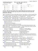
Circuit diagram
See Figure 1 below.
S
Hn
H1
G
V
DUT
Base plate
A
E
IEC
2976/10
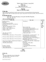
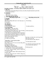
Figure 1 – Basic circuit diagram for isolation breakdown withstand
voltage test (“high pot test”) with V isol
–
Circuit description and requirements
DUT = Device under test
G = voltage source with high impedance, capable to supply V isol
S = main switch
V = voltmeter for V isol
Copyrighted material licensed to BR Demo by Thomson Reuters (Scientific), Inc., subscriptions.techstreet.com, downloaded on Nov-28-2014 by James Madison. No further reproduction or distribution is permitted. Uncontrolled when printe
60747-15 Ó IEC:2010
– 12 –
– 13 –
A = ammeter or current probe for I isol
H 1 …H n = high potential terminal
The voltage source G is capable to supply the isolation voltage V isol as the a. c. or d. c.
voltage with a high internal impedance to limit the possible breakthrough current in case of
breakdown of the DUT.
All main terminals and high voltage control terminals are connected together and connected
to the high potential output terminal H of the voltage source G. The base plate of the DUT,
respectively its metallized cooling surface and all low voltage terminals are connected to
ground potential E. An amperemeter or current probe A is applied to measure the isolation
leakage current.
–
Test procedure
Switch S is closed and the voltage is slowly raised to the specified value and maintained at
that value for the specified time. The current measured on ammeter A shall not exceed the
specified value. The voltage is then reduced to zero.
–
Specified conditions
Specified in IEC 60664-1:2007.
·
Ambient or case temperature
·
V isol
·
I isol as maximum test limit
·
Test time t, if less than 60 s
6.2
Methods of measurement
6.2.1
Partial discharge inception and extinction voltages (V i) (V e)
Between high potential terminals and base plate (where appropriate). See IEC 60270 and
IEC 60664-1:2007.
6.2.2
–
Parasitic inductance (L p )
Purpose
To measure the parasitic inductance between two main terminals
–
Circuit diagram
See Figure 2 below.
Copyrighted material licensed to BR Demo by Thomson Reuters (Scientific), Inc., subscriptions.techstreet.com, downloaded on Nov-28-2014 by James Madison. No further reproduction or distribution is permitted. Uncontrolled when printe
60747-15 Ó IEC:2010
+
T3
D3
C1
DUT
T1
Lp1
D1
G1
G
C
v CE
Ex1
E1/C2
T2
LL
D2
G2
Ex2
Lpn
E2
-
iDUT
IEC
2977/10
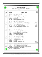
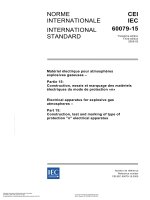
Figure 2 – Circuit diagram for measurement of parasitic inductances (L p)
Key
DUT
= devic e under test T1+T2, for example IGBT (Single or Dual – shown – or branch of a three phas e
arrangement), fast diode or MOSFET devic e
C
= main capacitor bank as res ervoir
LL
= load inductanc e, at least 100 times the parasitic inductanc e
L p1 …L pn = portions of parasitic inductanc e L p
IDUT
= current probe
G
= voltage s ource to charge the c apacitor
T1
= DUT, top switch (shown as IGBT in Figure 2)
T2
= DUT, bottom switch (shown as IGBT in Figure 2), optional
T3
= auxiliary IGBT switch
Copyrighted material licensed to BR Demo by Thomson Reuters (Scientific), Inc., subscriptions.techstreet.com, downloaded on Nov-28-2014 by James Madison. No further reproduction or distribution is permitted. Uncontrolled when printe
60747-15 Ó IEC:2010
– 14 –
– 15 –
VCC
V, I
vCE
Vstep
0
t1
t2
t
diDUT/dt
iDUT
IEC
2978/10
Figure 3 – Wave forms
–
Circuit description and requirements
The circuit of Figure 2 consists of a DC supply G for the charge reservoir C; T 3 is an auxiliary
switch, a gate drive unit for T 3, the DUT inserted into the test set-up with the gate control
terminals shorted, a dual channel oscilloscope, which senses the voltage V CE between main
terminals “C 1” and “E 2“, a current probe, which senses the current I DUT through the diode
path of the DUT, connected to the dual channel oscilloscope. This measuring method uses
reduced voltage V CC and the di/dt of diodes incorporated in the device at switch-off, sensing
the voltage at outside main terminals. This is usable for single switch devices as well as for
half bridge circuit devices (DUAL modules).
–
Measurement procedure
A pulsed current method is used. Auxiliary transistor T 3 switches the load current to the
inductor L L on and off. When T 3 is off, the current freewheels via the diodes of the DUT.
When T 3 switches on again, it causes the current through the diodes to fall at an almost linear
rate diDUT /dt. During this time (t 1 –t 2), the voltage across the DUT forms at step of Vstep
caused by the internal parasitic inductance at current decline (di DUT /dt). The value of the
parasitic inductance of the main current path can be calculated from
L p = Vstep / |(di DUT /dt)|
NOTE
6.2.3
–
(1)
Use low inductanc e (sheeted) bus baring and low inductance current probe.
Parasitic capacitance terminal to case (C p )
Purpose
To measure the parasitic capacitance C p between specified main terminal(s) and the case
(base plate)
–
Circuit diagram
See Figure 4 below.
Copyrighted material licensed to BR Demo by Thomson Reuters (Scientific), Inc., subscriptions.techstreet.com, downloaded on Nov-28-2014 by James Madison. No further reproduction or distribution is permitted. Uncontrolled when printe
60747-15 Ó IEC:2010
H
DUT
…
I1
V1
CM V2
I2
Cp
Base plate
IEC
2979/10
Figure 4 – Circuit diagram for measurement of parasitic capacitance (C p )
–
Circuit description and requirements
Cp
=
parasitic capacitance
H
=
high potential terminal
CM
=
capacitance meter
–
Measurement procedure
Mount the device to a grounded heat sink according to the manufacturer’s mounting
instructions. Connect the current source connector “I 1” of the capacitance meter CM to the
specified terminal and connector “I 2 ” to ground (base plate) of the DUT. Connect the voltage
sensing connector of the capacitance meter to test points “V 1” and “V 2 ” to ground. CM is set
to the specified frequency. The capacitance C p can be read on CM. For the measurement of
the total coupling capacitance C p connect all main terminals to each other and proceed with
the measurement like described above.
–
Specified conditions
· Measurement frequency f of the CM
6.2.4
6.2.4.1
–
Thermal characteristics
General description of measuring methods
Purpose
To measure thermal characteristics between the switch and the cooling system
–
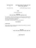
Reference points for temperature measurement and description
Same methods should be used as for the corresponding non-isolated device. Thermal
resistance and impedance are measured in the same way as described in the documents for
diodes IEC 60747-2, thyristors IEC 60747-6, bipolar transistors IEC 60747-7, FETs
IEC 60747-8 and IGBTs IEC 60747-9.
Copyrighted material licensed to BR Demo by Thomson Reuters (Scientific), Inc., subscriptions.techstreet.com, downloaded on Nov-28-2014 by James Madison. No further reproduction or distribution is permitted. Uncontrolled when printe
60747-15 Ó IEC:2010
– 16 –
– 17 –
Chip 1
Chip n
DUT
TsX
Tj1
Tj2
Tjn
Isolation layer
Base plate
Thermal interface material
Specified distance
External heat sink
Tc1
Tc2
Tsn
IEC
2980/10
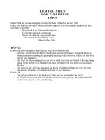
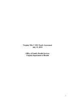
Key
T j1…n = junction temperature of chip 1 to n
T c1…n = case temperature under chip 1 to n
T s1...n = heatsink temperature under chip 1 to n
T sX = heatsink temperature at a specified surface point
Figure 5 – Cross-section of an isolated power device
with reference points for temperature measurement of T c and T s
–
Measurement procedure
T c is measured by a temperature measuring instrument from underneath through a small hole
through the heat sink and any thermal interface material underneath the switch (chip). T s is
taken from above at hottest accessible point, nearest to the switch (chip) or from underneath
through a specified sack hole ending at 2 (+/-1) mm below the heat sink surface (to be
specified, type test feature). T j is determined using indirect methods like described in the
individual documents.
NOTE The thermal resistance R th(j-s) and R th(c-s) depends on several mechanic al parameters such as type and
thickness of the used thermal interfac e material (should be specified in manufacturer’s mounting instructions, for
example 30 to 50mm), the max. deviation of flatness of the cooling surface of the device’s bas e plate and of the
heat sink and the mounting torque of the fixing screws, as per specified mounting instructions.
6.2.4.2
Thermal resistance junction to case per switch R th(j-c)
R th(j-c) = (T j - T c )/P
(2)
where
Tj
is the virtual junction temperature of the switch;
Tc
is the temperature of the case (base plate) under the switch (chip);
P
is the power dissipation of a switch (see Figure 5).
6.2.4.3
Thermal resistance case to heat sink per switch (X) R th(c-s)X or per device
R th(c-s)
R th(c-s)(X) = (T c - T s )/P X
where
(3)
Copyrighted material licensed to BR Demo by Thomson Reuters (Scientific), Inc., subscriptions.techstreet.com, downloaded on Nov-28-2014 by James Madison. No further reproduction or distribution is permitted. Uncontrolled when printe
60747-15 Ó IEC:2010
60747-15 Ó IEC:2010
X
is the D (Diode), I (IGBT); M (MOSFET)
Tc
is the temperature taken at the specified point of the case (as above) under the chip
Ts
is the temperature of the heat sink, taken at the reference point for testing T s specified
PX
is the complete power dissipation of the switch
P
is the power dissipation of the complete device
–
Specified conditions
· Mounting according manufacturer’s instructions
· Thermal conductivity of the thermal interface material
· Reference points for thermal measurement
NOTE
See Annex B for Measuring method of the thickness of thermal interface material.
6.2.4.4
Thermal resistance junction to heat sink per switch Rth(j-s) (for heat sink
rated devices)
R th(j-s) = (T j - T sn )/P
(4)
where
Tj
is the virtual junction temperature of the switch;
T sn
is taken at the specified reference point n at the heatsink (see Figure 5);
P
is the power dissipation of the switch.
–
Specified conditions
· Mounting according manufacturer’s instructions
· Thermal conductivity of the thermal interface material
· Reference points for thermal measurement
6.2.4.5
–
Transient thermal impedance Z th
Measurement circuit and procedure
These are based on former Subclause 6.2.4.2 to 6.2.4.4. Individual documents of the noninsulated devices apply.
–
Z th(j-c) = (|T j(0) - T c (0)| - |T j (t) - T c (t)|)/P
(5)
Z th(c-s) = (|T c (0) - T s (0)| - |T c (t) - T s (t)|)/P
(6)
Z th(j-s) = (|T j(0) - T s (0)| - |T j (t) - T s (t)|)/P
(7)
Specified conditions
· Mounting according manufacturer’s instructions
· Thermal conductivity of the thermal interface material
· Reference points for thermal measurement
7
7.1
Acceptance and reliability
General requirements
In addition to the following subclauses, the requirements applicable to the non-isolated
devices as given in the other relevant parts of IEC 60747 apply.
Copyrighted material licensed to BR Demo by Thomson Reuters (Scientific), Inc., subscriptions.techstreet.com, downloaded on Nov-28-2014 by James Madison. No further reproduction or distribution is permitted. Uncontrolled when printe
– 18 –