Iec 60747 16 4 2011
Bạn đang xem bản rút gọn của tài liệu. Xem và tải ngay bản đầy đủ của tài liệu tại đây (551.5 KB, 62 trang )
®
Edition 1.1
2011-04
INTERNATIONAL
STANDARD
NORME
INTERNATIONALE
Semiconductor devices –
Part 16-4: Microwave integrated circuits – Switches
IEC 60747-16-4:2004+A1:2009
Dispositifs à semiconducteurs –
Partie 16-4: Circuits intégrés hyperfréquences – Commutateurs
colour
inside
Copyrighted material licensed to BR Demo by Thomson Reuters (Scientific), Inc., subscriptions.techstreet.com, downloaded on Nov-28-2014 by James Madison. No further reproduction or distribution is permitted. Uncontrolled when printe
IEC 60747-16-4
Copyright © 2011 IEC, Geneva, Switzerland
All rights reserved. Unless otherwise specified, no part of this publication may be reproduced or utilized in any form or by
any means, electronic or mechanical, including photocopying and microfilm, without permission in writing from either IEC or
IEC's member National Committee in the country of the requester.
If you have any questions about IEC copyright or have an enquiry about obtaining additional rights to this publication,
please contact the address below or your local IEC member National Committee for further information.
Droits de reproduction réservés. Sauf indication contraire, aucune partie de cette publication ne peut être reproduite
ni utilisée sous quelque forme que ce soit et par aucun procédé, électronique ou mécanique, y compris la photocopie
et les microfilms, sans l'accord écrit de la CEI ou du Comité national de la CEI du pays du demandeur.
Si vous avez des questions sur le copyright de la CEI ou si vous désirez obtenir des droits supplémentaires sur cette
publication, utilisez les coordonnées ci-après ou contactez le Comité national de la CEI de votre pays de résidence.
IEC Central Office
3, rue de Varembé
CH-1211 Geneva 20
Switzerland
Email:
Web: www.iec.ch
About the IEC
The International Electrotechnical Commission (IEC) is the leading global organization that prepares and publishes
International Standards for all electrical, electronic and related technologies.
About IEC publications
The technical content of IEC publications is kept under constant review by the IEC. Please make sure that you have the
latest edition, a corrigenda or an amendment might have been published.
Catalogue of IEC publications: www.iec.ch/searchpub
The IEC on-line Catalogue enables you to search by a variety of criteria (reference number, text, technical committee,…).
It also gives information on projects, withdrawn and replaced publications.
IEC Just Published: www.iec.ch/online_news/justpub
Stay up to date on all new IEC publications. Just Published details twice a month all new publications released. Available
on-line and also by email.
Electropedia: www.electropedia.org
The world's leading online dictionary of electronic and electrical terms containing more than 20 000 terms and definitions
in English and French, with equivalent terms in additional languages. Also known as the International Electrotechnical
Vocabulary online.
Customer Service Centre: www.iec.ch/webstore/custserv
If you wish to give us your feedback on this publication or need further assistance, please visit the Customer Service
Centre FAQ or contact us:
Email:
Tel.: +41 22 919 02 11
Fax: +41 22 919 03 00
A propos de la CEI
La Commission Electrotechnique Internationale (CEI) est la première organisation mondiale qui élabore et publie des
normes internationales pour tout ce qui a trait à l'électricité, à l'électronique et aux technologies apparentées.
A propos des publications CEI
Le contenu technique des publications de la CEI est constamment revu. Veuillez vous assurer que vous possédez
l’édition la plus récente, un corrigendum ou amendement peut avoir été publié.
Catalogue des publications de la CEI: www.iec.ch/searchpub/cur_fut-f.htm
Le Catalogue en-ligne de la CEI vous permet d’effectuer des recherches en utilisant différents critères (numéro de référence,
texte, comité d’études,…). Il donne aussi des informations sur les projets et les publications retirées ou remplacées.
Just Published CEI: www.iec.ch/online_news/justpub
Restez informé sur les nouvelles publications de la CEI. Just Published détaille deux fois par mois les nouvelles
publications parues. Disponible en-ligne et aussi par email.
Electropedia: www.electropedia.org
Le premier dictionnaire en ligne au monde de termes électroniques et électriques. Il contient plus de 20 000 termes et
définitions en anglais et en franỗais, ainsi que les termes ộquivalents dans les langues additionnelles. Egalement appelé
Vocabulaire Electrotechnique International en ligne.
Service Clients: www.iec.ch/webstore/custserv/custserv_entry-f.htm
Si vous désirez nous donner des commentaires sur cette publication ou si vous avez des questions, visitez le FAQ du
Service clients ou contactez-nous:
Email:
Tél.: +41 22 919 02 11
Fax: +41 22 919 03 00
Copyrighted material licensed to BR Demo by Thomson Reuters (Scientific), Inc., subscriptions.techstreet.com, downloaded on Nov-28-2014 by James Madison. No further reproduction or distribution is permitted. Uncontrolled when printe
THIS PUBLICATION IS COPYRIGHT PROTECTED
®
Edition 1.1
2011-04
INTERNATIONAL
STANDARD
NORME
INTERNATIONALE
colour
inside
Semiconductor devices –
Part 16-4: Microwave integrated circuits – Switches
Dispositifs à semiconducteurs –
Partie 16-4: Circuits intégrés hyperfréquences – Commutateurs
INTERNATIONAL
ELECTROTECHNICAL
COMMISSION
COMMISSION
ELECTROTECHNIQUE
INTERNATIONALE
PRICE CODE
CODE PRIX
ICS 31.080.99
® Registered trademark of the International Electrotechnical Commission
Marque déposée de la Commission Electrotechnique Internationale
CL
ISBN 978-2-88912-773-3
Copyrighted material licensed to BR Demo by Thomson Reuters (Scientific), Inc., subscriptions.techstreet.com, downloaded on Nov-28-2014 by James Madison. No further reproduction or distribution is permitted. Uncontrolled when printe
IEC 60747-16-4
60747-16-4 IEC:2004+A1:2009
CONTENTS
FOREWORD ........................................................................................................................... 3
1
Scope ............................................................................................................................... 5
2
Normative references ....................................................................................................... 5
3
Terms and definitions ....................................................................................................... 6
4
Essential ratings and characteristics ................................................................................. 7
5
4.1 Circuit identification and types ................................................................................. 7
4.2 Application description ............................................................................................ 8
4.3 Specification of the function .................................................................................... 8
4.4 Limiting values (absolute maximum rating system) ................................................ 10
4.5 Operating conditions (within the specified operating temperature range) ............... 11
4.6 Electrical characteristics ........................................................................................ 12
4.7 Mechanical and environmental ratings, characteristics and data ............................ 12
4.8 Additional information ............................................................................................ 13
Measuring methods ........................................................................................................ 13
5.1
5.2
5.3
5.4
5.5
5.6
5.7
5.8
General ................................................................................................................. 13
Insertion loss (L ins ) ................................................................................................ 14
Isolation (L iso ) ....................................................................................................... 16
Return loss (L ret ) ................................................................................................... 17
Input power at 1 dB compression (P i(1dB) ) and output power at 1 dB
compression (P o(1dB) ) ............................................................................................ 19
Turn-on time (t on ), turn-off time (t off ), rise time (t r(out) ), and fall time (t f(out) ) ........... 20
Adjacent channel power ratio (P o(mod) /P adj ) .......................................................... 22
nth order harmonic distortion ratio (P nth /P 1 ) (P 1 /P nth ) ............................................ 26
Bibliography .......................................................................................................................... 28
Figure 1 – Circuit diagram for the measurement of the insertion loss L ins .............................. 14
Figure 2 – Circuit diagram for the measurement of the isolation L iso ..................................... 16
Figure 3 – Circuit for the measurements of the return loss .................................................... 17
Figure 4 – Circuit for the measurements of switching time .................................................... 20
Figure 5 – Input and output waveforms ................................................................................. 21
Figure 6 – Circuit for the measurement of the adjacent channel power ratio .......................... 23
Figure 7 – Circuit diagram for the n-th order harmonic distortion ratio ................................... 26
Copyrighted material licensed to BR Demo by Thomson Reuters (Scientific), Inc., subscriptions.techstreet.com, downloaded on Nov-28-2014 by James Madison. No further reproduction or distribution is permitted. Uncontrolled when printe
–2–
–3–
INTERNATIONAL ELECTROTECHNICAL COMMISSION
____________
SEMICONDUCTOR DEVICES –
Part 16-4: Microwave integrated circuits –
Switches
FOREWORD
1) The International Electrotechnical Commission (IEC) is a worldwide organization for standardization comprising
all national electrotechnical committees (IEC National Committees). The object of IEC is to promote
international co-operation on all questions concerning standardization in the electrical and electronic fields. To
this end and in addition to other activities, IEC publishes International Standards, Technical Specifications,
Technical Reports, Publicly Available Specifications (PAS) and Guides (hereafter referred to as “IEC
Publication(s)”). Their preparation is entrusted to technical committees; any IEC National Committee interested
in the subject dealt with may participate in this preparatory work. International, governmental and nongovernmental organizations liaising with the IEC also participate in this preparation. IEC collaborates closely
with the International Organization for Standardization (ISO) in accordance with conditions determined by
agreement between the two organizations.
2) The formal decisions or agreements of IEC on technical matters express, as nearly as possible, an international
consensus of opinion on the relevant subjects since each technical committee has representation from all
interested IEC National Committees.
3) IEC Publications have the form of recommendations for international use and are accepted by IEC National
Committees in that sense. While all reasonable efforts are made to ensure that the technical content of IEC
Publications is accurate, IEC cannot be held responsible for the way in which they are used or for any
misinterpretation by any end user.
4) In order to promote international uniformity, IEC National Committees undertake to apply IEC Publications
transparently to the maximum extent possible in their national and regional publications. Any divergence
between any IEC Publication and the corresponding national or regional publication shall be clearly indicated in
the latter.
5) IEC itself does not provide any attestation of conformity. Independent certification bodies provide conformity
assessment services and, in some areas, access to IEC marks of conformity. IEC is not responsible for any
services carried out by independent certification bodies.
6) All users should ensure that they have the latest edition of this publication.
7) No liability shall attach to IEC or its directors, employees, servants or agents including individual experts and
members of its technical committees and IEC National Committees for any personal injury, property damage or
other damage of any nature whatsoever, whether direct or indirect, or for costs (including legal fees) and
expenses arising out of the publication, use of, or reliance upon, this IEC Publication or any other IEC
Publications.
8) Attention is drawn to the Normative references cited in this publication. Use of the referenced publications is
indispensable for the correct application of this publication.
9) Attention is drawn to the possibility that some of the elements of this IEC Publication may be the subject of
patent rights. IEC shall not be held responsible for identifying any or all such patent rights.
This consolidated version of IEC 60747-16-4 consists of the first edition (2004)
[documents 47E/256/FDIS and 47E/261/RVD] and its amendment 1 (2009) [documents
47E/358/CDV and 47E/373/RVC]. It bears the edition number 1.1.
The technical content is therefore identical to the base edition and its amendment and
has been prepared for user convenience. A vertical line in the margin shows where the
base publication has been modified by amendment 1. Additions and deletions are
displayed in red, with deletions being struck through.
Copyrighted material licensed to BR Demo by Thomson Reuters (Scientific), Inc., subscriptions.techstreet.com, downloaded on Nov-28-2014 by James Madison. No further reproduction or distribution is permitted. Uncontrolled when printe
60747-16-4 IEC:2004+A1:2009
60747-16-4 IEC:2004+A1:2009
International Standard IEC 60747-16-4 has been prepared by subcommittee 47E: Discrete
semiconductor devices, of IEC technical committee 47: Semiconductor devices.
The French version of this standard has not been voted upon.
This bilingual consolidated version (2011-11) replaces the English version.
This publication has been drafted in accordance with the ISO/IEC Directives, Part 2.
The committee has decided that the contents of the base publication and its amendments will
remain unchanged until the stability date indicated on the IEC web site under
"" in the data related to the specific publication. At this date, the
publication will be
•
reconfirmed,
•
withdrawn,
•
replaced by a revised edition, or
•
amended.
IMPORTANT – The “colour inside” logo on the cover page of this publication indicates
that it contains colours which are considered to be useful for the correct understanding
of its contents. Users should therefore print this publication using a colour printer.
Copyrighted material licensed to BR Demo by Thomson Reuters (Scientific), Inc., subscriptions.techstreet.com, downloaded on Nov-28-2014 by James Madison. No further reproduction or distribution is permitted. Uncontrolled when printe
–4–
–5–
SEMICONDUCTOR DEVICES –
Part 16-4: Microwave integrated circuits –
Switches
1
Scope
This part of IEC 60747 provides new measuring methods, terminology and letter symbols, as
well as essential ratings and characteristics for integrated circuit microwave switches.
There are many combinations for RF ports in switches, such as SPST (single pole single
throw), SPDT (single pole double throw), SP3T (single pole triple throw), DPDT (double pole
double throw), etc. Switches in this standard are based on SPDT. However, this standard is
applicable to the other types of switches.
2
Normative references
The following referenced documents are indispensable for the application of this document.
For dated references, only the edition cited applies. For undated references, the latest edition
of the referenced document (including any amendments) applies.
IEC 60617-12, Graphical symbols for diagrams – Part 12: Binary logic elements
IEC 60617-13, Graphical symbols for diagrams – Part 13: Analogue elements
IEC 60617, Graphical symbols for diagrams
IEC 60747-1(1983), Semiconductor devices – Discrete devices and integrated circuits –
Part 1: General
Amendment 3 (1996)
IEC 60747-1:2006, Semiconductor devices – Part 1: General
IEC 60747-4, Semiconductor devices – Discrete devices – Part 4: Microwave devices
IEC 60747-16-1:2001, Semiconductor devices – Part 16-1: Microwave integrated circuits –
Amplifiers
Amendment 1 (2007) 1
IEC 60748-2, Semiconductor devices – Integrated circuits – Part 2: Digital integrated circuits
IEC 60748-3, Semiconductor devices – Integrated circuits – Part 3: Analogue integrated
circuits
IEC 60748-4, Semiconductor devices – Integrated circuits – Part 4: Interface integrated
circuits
IEC 61340-5-1:2007, Electrostatics – Part 5-1: Protection of electronic devices from
electrostatic phenomena – General requirements
IEC/TR 61340-5-2:2007, Electrostatics – Part 5-2: Protection of electronic devices from
electrostatic phenomena – User guide
___________
1
There exists a consolidated edition 1.1 published in 2007, including the base publication (2001) and its
Amendment 1 (2007).
Copyrighted material licensed to BR Demo by Thomson Reuters (Scientific), Inc., subscriptions.techstreet.com, downloaded on Nov-28-2014 by James Madison. No further reproduction or distribution is permitted. Uncontrolled when printe
60747-16-4 IEC:2004+A1:2009
3
60747-16-4 IEC:2004+A1:2009
Terms and definitions
For the purposes of this document, the following terms and definitions apply.
Terms related to electrical characteristics
3.1
insertion loss
L ins
ratio of the out input power to the output power at the switched on port, to the input power in
the linear region of the power transfer curve P o (dBm) = f(Pi)
NOTE 1
In this region, ∆P o (dBm) = ∆P i (dBm).
NOTE 2
Usually the insertion loss is expressed in decibels.
3.2
isolation
L iso
ratio of the out input power to the output power at the switched off port, to the input power in
the linear region of the power transfer curve P o (dBm) = f(P i)
NOTE 1
In this region, ∆P o (dBm) = ∆P i (dBm).
NOTE 2
Usually the isolation is expressed in decibels.
3.3
return loss
L ret
ratio of the incident power P inc at the specified port to the reflected power P ref at the same
port in the linear region of the power transfer curve P ref (dBm) = f(P inc )
NOTE 1
In this region, ∆P ref (dBm) = ∆P inc (dBm).
NOTE 2
Usually the return loss is expressed in decibels.
3.4
input power at 1 dB compression
P i(1 dB)
input power where the insertion loss increases by 1 dB compared with insertion loss in linear
region
3.5
output power at 1 dB compression
P o(1dB)
output power where the insertion loss increases by 1 dB compared with insertion loss in linear
region
3.6
turn on time
t on
interval between the lower reference point on the leading edge of the control voltage and the
upper reference point on the leading edge of the envelope of the output voltage in the linear
region of the power transfer curve P o (dBm) = f(P i)
NOTE
In this region, ∆P o (dBm) = ∆P i (dBm).
3.7
turn off time
t off
interval between the upper reference point on the trailing edge of the control voltage and the
lower reference point on the trailing edge of the envelope of the output voltage in the linear
region of the power transfer curve P o (dBm) = f(P i)
NOTE
In this region, ∆P o (dBm) = ∆P i (dBm).
Copyrighted material licensed to BR Demo by Thomson Reuters (Scientific), Inc., subscriptions.techstreet.com, downloaded on Nov-28-2014 by James Madison. No further reproduction or distribution is permitted. Uncontrolled when printe
–6–
–7–
3.8
rise time
t r(out)
interval between the lower reference point on the leading edge of the output voltage and the
upper reference point on the leading edge of the envelope of the output voltage in the linear
region of the power transfer curve P o (dBm) = f(P i)
NOTE
In this region, ∆P o (dBm) = ∆P i (dBm).
3.9
fall time
t f(out)
interval between the upper reference point on the trailing edge of the output voltage and the
lower reference point on the trailing edge of the envelope of the output voltage in the linear
region of the power transfer curve P o (dBm) = f(P i)
NOTE
In this region, ∆P o (dBm) = ∆P i (dBm).
3.10
adjacent channel power ratio
P o(mod) /P adj
ratio of the total power in the specified carrier signal frequency band to total output power in
the specified frequency band away from the specified carrier signal frequency, at the specified
output power when the modulation signal is supplied
3.11
n-th order harmonic distortion ratio
P nth /P 1
See 3.14 of IEC 60747-16-1(2001).
nth order harmonic distortion ratio
P 1 /P nth
See 3.14 of Amendment 1 of IEC 60747-16-1:2007.
4
Essential ratings and characteristics
This clause gives ratings and characteristics required for specifying integrated circuit microwave switches.
4.1
4.1.1
Circuit identification and types
Designation and types
Identification of type (device name), category of circuit and technology applied should be
given. Microwave switches comprise one category.
4.1.2
General function description
A general description of the function performed by the integrated circuit microwave switches
and the features for the application should be made.
4.1.3
Manufacturing technology
The manufacturing technology, e.g. semiconductor monolithic integrated circuit, thin film
integrated circuit, micro-assembly, etc. should be stated. This statement should include
details of the semiconductor technologies such as Schottky-barrier diode, PIN diode, MESFET,
Si bipolar transistor, etc.
IEC 60747-4 should be referred to for terminology and letter symbols, essential ratings and
characteristics and measuring methods of such microwave devices.
Copyrighted material licensed to BR Demo by Thomson Reuters (Scientific), Inc., subscriptions.techstreet.com, downloaded on Nov-28-2014 by James Madison. No further reproduction or distribution is permitted. Uncontrolled when printe
60747-16-4 IEC:2004+A1:2009
4.1.4
60747-16-4 IEC:2004+A1:2009
Package identification
The following statements should be made:
a) chip or packaged form;
b) IEC and/or national reference number of the outline drawing, of or drawing of nonstandard package including terminal numbering;
c) principal package material, for example, metal, ceramic, plastic.
4.1.5
Main application
The main application should be stated. If the device has restrictive applications, these should
be stated here.
4.2
Application description
Information on application of the integrated circuit and its relation to the associated devices
should be given.
4.2.1
Conformance to system and/or interface information
It should be stated whether the integrated circuit conforms to an application system and/or an
interface standard or a recommendation.
Detailed information concerning application systems, equipment and circuits such as VSAT
systems, DBS receivers, microwave landing systems, etc. should also be given.
4.2.2
Overall block diagram
A block diagram of the applied systems should be given if necessary.
4.2.3
Reference data
The most important properties that permit comparison between derivative types should be
given.
4.2.4
Electrical compatibility
It should be stated whether the integrated circuit is electrically compatible with other particular
integrated circuits, or families of integrated circuits, or whether special interfaces are required.
Details should be given concerning the type of input and output circuits, e.g. input/output
impedances, d.c. block, open-drain, etc. Interchangeability with other devices, if any, should
also be given.
4.2.5
Associated devices
If applicable, the following should be stated:
–
devices necessary for correct operation (list with type number, name and function);
–
peripheral devices with direct interfacing (list with type number, name and function).
4.3
4.3.1
Specification of the function
Detailed block diagram – Functional blocks
A detail block diagram or equivalent circuit information of the integrated circuit microwave
switches should be given. The block diagram should be composed of the following:
Copyrighted material licensed to BR Demo by Thomson Reuters (Scientific), Inc., subscriptions.techstreet.com, downloaded on Nov-28-2014 by James Madison. No further reproduction or distribution is permitted. Uncontrolled when printe
–8–
–9–
a)
functional blocks;
b)
mutual interconnections among the functional blocks;
c)
individual functional units within the functional blocks;
d)
mutual interconnections among the individual functional blocks;
e)
function of each external connection;
f)
inter-dependence between the separate functional blocks.
The block diagram should identify the function of each external connection and, where no
ambiguity can arise, also show the terminal symbols and/or numbers. If the encapsulation has
metallic parts, any connection to them from external terminals should be indicated. The
connections with any associated external electrical elements should be stated, where
necessary.
As additional information, the complete electrical circuit diagram can be reproduced, but not
necessarily with indications of the values of the circuit components. The graphical symbol for
the function shall be given. Rules governing such diagrams may be obtained from IEC 60617-12
or IEC 60617-13.
4.3.2
Identification and function of terminals
All terminals should be identified on the block diagram (supply terminals, input or output
terminals, input/output terminals).
The terminal functions 1) to 4) should be indicated in a table as follows:
Terminal
number
Terminal
symbol
1) Terminal
designation
Function of terminal
2) Function
3) Input/output
identification
4) Type of input/
output circuits
1) Terminal designation
A terminal designation to indicate the function of the terminal should be given. Supply
terminals, ground terminals, blank terminals (with abbreviation NC), non-usable terminals
(with abbreviation NU) should be distinguished.
2) Function
A brief indication of the terminal function should be given:
–
each function of multi-role terminals, i.e. terminals having multiple functions;
–
each function of integrated circuit selected by mutual pin connections, programming
and/or application of function selection data to the function selection pin, such as
mode selection pin.
3) Input/output identification
Input, output, input/output and multiplex input/output terminals should be distinguished.
4) Type of input/output circuits
The type of input and output circuit, e.g. input/output impedances, with or without d.c.
block, etc., should be distinguished.
5) Type of ground
If the baseplate of the package is used as ground, this should be stated.
Copyrighted material licensed to BR Demo by Thomson Reuters (Scientific), Inc., subscriptions.techstreet.com, downloaded on Nov-28-2014 by James Madison. No further reproduction or distribution is permitted. Uncontrolled when printe
60747-16-4 IEC:2004+A1:2009
60747-16-4 IEC:2004+A1:2009
Example:
Bias supply voltage(s) Control supply voltage(s)
Input(s)
NU
Integrated
circuit
microwave
switch
NC
Output(s)
Ground
4.3.3
Function description
The function performed by the circuit should be specified, including the following information:
–
basic function;
–
relation to external terminals;
–
operation mode (e.g., set-up method, preference, etc.);
–
interrupt handling.
4.3.4
Family related characteristics
In this part, all the family specific functional descriptions shall be stated (referred to
IEC 60748-2, IEC 60748-3 and IEC 60748-4).
If ratings and characteristics, as well as function characteristics exist for the family, the
relevant part of IEC 60748 should be used (e.g. for microprocessors, see IEC 60748-2,
Chapter III, Section Three).
NOTE
For each new device family, specific items should be added the relevant part of IEC 60748.
4.4
Limiting values (absolute maximum rating system)
The table for these values should contain the following:
–
Any interdependence of limiting conditions shall be specified.
–
If externally connected and/or attached elements, for example heatsinks, have an
influence on the values of the ratings, the ratings shall be prescribed for the integrated
circuit with the elements connected and/or attached.
–
If limiting values are exceeded for transient overload, the permissible excess and their
durations shall be specified.
–
Where minimum and maximum values differ during programming of the device, this should
be stated.
–
All voltages are referenced to a specified reference terminal (V ss , ground, etc.).
In satisfying the following clauses, if maximum and/or minimum values are quoted, the
manufacturer shall indicate whether he refers to the absolute magnitude or to the
algebraic value of the quantity.
–
–
The ratings given shall cover the operation of the multi-function integrated circuit over the
specified range of operating temperatures. Where such ratings are temperature-dependent,
these dependence should be indicated.
Copyrighted material licensed to BR Demo by Thomson Reuters (Scientific), Inc., subscriptions.techstreet.com, downloaded on Nov-28-2014 by James Madison. No further reproduction or distribution is permitted. Uncontrolled when printe
– 10 –
4.4.1
– 11 –
Electrical limiting values
Limiting values should be specified as follows:
Subclause
Parameters
Min.
Max.
4.4.1.1
Bias supply voltage(s) (where appropriate)
+
4.4.1.2
Bias supply current(s) (where appropriate)
+
4.4.1.3
Control supply voltage(s) (where appropriate)
+
4.4.1.4
Control supply current(s) (where appropriate)
+
4.4.1.5
Terminal voltage(s) (where appropriate)
4.4.1.6
Terminal current(s) (where appropriate)
+
4.4.1.7
Input power
+
4.4.1.8
Power dissipation
+
+
+
NOTE It is necessary to select either 4.4.1.1 or 4.4.1.2, either 4.4.1.3 or 4.4.1.4, and either
4.4.1.5 or 4.4.1.6.
The detail specification may indicate those values within the table including notes 1 and 2.
Parameters (Note 1, Note 2)
Symbols
Min.
NOTE 1
Where appropriate, in accordance with the type of circuit considered.
NOTE 2
For power supply voltage range:
Max.
Unit
–
limiting value(s) of the continuous voltage(s) at the supply terminal(s) with respect to a special electrical
reference point;
–
where appropriate, limiting value between specified supply terminals;
–
when more than one voltage supply is required, a statement should be made as to whether the sequence in
which these supplies are applied is significant: if so, the sequence should be stated;
–
when more than one supply is needed, it may be necessary to state the combinations of ratings for these supply
voltages and currents.
4.4.2
Temperatures
a) Operating temperature (ambient or reference-point temperature)
b) Ambient or case temperature
c b)
Storage temperature
d c)
Channel temperature
e d)
Lead temperature (for soldering).
The detail specification may indicate those values within the table including the note.
Parameters (Note)
Symbols
Min.
Max.
NOTE
Where appropriate, in accordance with the type of circuit considered.
4.5
Operating conditions (within the specified operating temperature range)
They are not to be inspected, but may be used for quality assessment purposes.
Unit
Copyrighted material licensed to BR Demo by Thomson Reuters (Scientific), Inc., subscriptions.techstreet.com, downloaded on Nov-28-2014 by James Madison. No further reproduction or distribution is permitted. Uncontrolled when printe
60747-16-4 IEC:2004+A1:2009
60747-16-4 IEC:2004+A1:2009
4.5.1
Power supplies – Positive and/or negative values
4.5.2
Initialization sequences (where appropriate)
If special initialization sequences are necessary, power supply sequencing and initialization
procedure should be specified.
4.5.3
Input voltage(s) (where appropriate)
4.5.4
Output current(s) (where appropriate)
4.5.5
Voltage and/or current of other terminal(s)
4.5.6
External elements (where appropriate)
4.5.7
Operating temperature range
4.6
Electrical characteristics
The characteristics shall apply over the full operating temperature range, unless otherwise
specified. Each characteristic of 4.6.1 and 4.6.2 should be stated either
a) over the specified range of operating temperatures, or
b) at a temperature of 25 °C, and at maximum and minimum operating temperatures.
The parameters should be specified corresponding to the type as follows:
Subclause
Parameters
Min.
Typical a
Max.
4.6.1
Bias supply operating current
+
+
4.6.2
Control supply operating current
+
+
4.6.3
Insertion loss
+
+
4.6.4
Isolation (where appropriate)
4.6.5
4.6.6
+
Return loss
b
+
+
+
Input power at 1 dB compression point (where appropriate)
+
+
4.6.7
Output power at 1 dB compression point (where appropriate)
+
+
4.6.8
Turn-on time
+
+
4.6.9
Turn-off time
+
+
4.6.10
Rise time (where appropriate)
+
+
4.6.11
Fall time (where appropriate)
+
+
4.6.12
Adjacent channel power ratio (where appropriate)
+
+
+
4.6.13
nth order harmonic distortion ratio (where appropriate)
+
+
+
a
b
Optional.
It is necessary to select either 4.6.6 or 4.6.7.
The detail specification may indicate those values within the table.
Characteristics
a
Symbols
Conditions
Min.
Typical a
Max.
Units
Optional.
4.7
Mechanical and environmental ratings, characteristics and data
Any specific mechanical and environmental ratings applicable should be stated (see also 5.10
and 5.11 of IEC 60747-1, Chapter VI, Clause 7).
Copyrighted material licensed to BR Demo by Thomson Reuters (Scientific), Inc., subscriptions.techstreet.com, downloaded on Nov-28-2014 by James Madison. No further reproduction or distribution is permitted. Uncontrolled when printe
– 12 –
4.8
– 13 –
Additional information
Where appropriate, the following information should be given:
4.8.1
Equivalent input and output circuit
Detail information should be given regarding the type of input and output circuits, e.g.
input/output impedances, d.c. block, open-drain, etc.
4.8.2
Internal protection
A statement shall be given to indicate whether the integrated circuit contains internal
protection against high static voltages or electrical fields.
4.8.3
Capacitors at terminals
If capacitors for the input/output d.c. block are needed, these capacitances should be stated.
4.8.4
Thermal resistance
4.8.5
Interconnections to other types of circuit
Where appropriate, details of the interconnections to other circuits should be given.
4.8.6
Effects of externally connected component(s)
Curves or data indicating the effect of externally connected component(s) that influence the
characteristics may be given.
4.8.7
Recommendations for any associated device(s)
For example, decoupling of power supply to a high-frequency device should be stated.
4.8.8
Handling precautions
Where appropriate, handling precautions specific to the circuit should be stated (see also
IEC 61340-5-1 and IEC 61340-5-2, concerning electrostatic-sensitive devices IEC 60747-1,
Chapter IX: electrostatic-sensitive devices).
4.8.9
Application data
4.8.10
Other application information
4.8.11
Date of issue of the data sheet
5
Measuring methods
5.1
General
This clause prescribes measuring methods for electrical characteristics of integrated circuit
microwave switches used at microwave frequency bands.
5.1.1
General precautions
The general precautions listed in Clause 2 of IEC 60747-1, Chapter VII, Section One 6.3, 6.4
and 6.6 of IEC 60747-1:2006 apply. In addition, special care should be taken to use low-ripple
d.c. supplies and to decouple adequately all bias supply voltages at the frequency of
measurement. Although the level of the input and/or output signal can be specified in either
power or voltage, in this standard it is expressed in power, unless otherwise specified.
Copyrighted material licensed to BR Demo by Thomson Reuters (Scientific), Inc., subscriptions.techstreet.com, downloaded on Nov-28-2014 by James Madison. No further reproduction or distribution is permitted. Uncontrolled when printe
60747-16-4 IEC:2004+A1:2009
5.1.2
60747-16-4 IEC:2004+A1:2009
Characteristic impedances
The input and output characteristic impedances of the measurement system, shown in the
circuit in this standard, are 50 Ω. If they are not 50 Ω, they should be specified.
5.1.3
Handling precautions
When handling electrostatic-sensitive devices, the handling precautions given in Clause 1 of
IEC 60747-1, Chapter IX IEC 61340-5-1 and IEC 61340-5-2, shall be observed.
5.1.4
Types
The devices in this standard are both packaged and chip types, measured using suitable test
fixtures.
5.2
5.2.1
Insertion loss (L ins )
Purpose
To measure the insertion loss under specified conditions.
5.2.2
Circuit diagram
Variable
attenuator
Signal
generator Isolator
Gf
Termination
dB
f
Termination
Frequency
meter
Device being
measured
A
C
Termination
G
D
E
B
Power
meter 1
Bias
supply
Spectrum
analyser
Attenuator
W
W
V
dB
Termi- Power
nation meter 2
V
A
A
Control
supply
IEC 1018/04
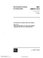
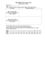
NOTE 1 Connect the point C to the input port, the point D to one of the output ports, and the point G to the other
output port of the device being measured.
NOTE 2
The control bias is supplied to become ON between the point C and D.
Figure 1 – Circuit diagram for the measurement of the insertion loss L ins
5.2.3
Principle of measurement
Insertion loss L ins is derived from the input power P i in dBm and the output power P o in dBm
of the device being measured as follows:
Lins = P1 – Po
L ins = P i – P o
(1)
Copyrighted material licensed to BR Demo by Thomson Reuters (Scientific), Inc., subscriptions.techstreet.com, downloaded on Nov-28-2014 by James Madison. No further reproduction or distribution is permitted. Uncontrolled when printe
– 14 –
– 15 –
In the circuit diagram shown in Figure 1, P i and P o are derived from the following equations:
Pi = P1 − L1
(2)
Po = P2 + L2
(3)
where
P 1 is the value indicated by the power meter 1;
P 2 is the value indicated by the power meter 2;
L 1 is the power at the point B in dBm, less the power at the point C in dBm;
L 2 is the power at the point D in dBm, less the power at the point E in dBm.
P i , P o , P 1 and P 2 are expressed in dBm. L ins , L 1 and L 2 are expressed in dB.
5.2.4
Circuit description and requirements
The purpose of the isolator is to enable the power level to the device being measured to be
kept constant, irrespective of impedance mismatched at its input. The value of L 1 and L 2
should be measured beforehand.
5.2.5
Precautions to be observed
Harmonics or spurious responses from the signal generator should be reduced so as to be
negligible. Insertion loss L ins shall be measured without the influence at the input and output
ports.
5.2.6
Measurement procedure
The frequency of the signal generator shall be set to the specified value.
The bias under specified conditions shall be is applied as specified.
An adequate input power shall be applied to the device being measured.
By varying the input power, confirm that a change of output power in dBm is the same as that
of the input power.
The value P 1 is measured at the power meter 1.
The value P 2 is measured at the power meter 2.
The insertion loss is calculated from Equations (2), (3) and (1).
5.2.7
Specified conditions
–
Ambient or reference-point temperature
–
Bias conditions
–
Frequency.
Copyrighted material licensed to BR Demo by Thomson Reuters (Scientific), Inc., subscriptions.techstreet.com, downloaded on Nov-28-2014 by James Madison. No further reproduction or distribution is permitted. Uncontrolled when printe
60747-16-4 IEC:2004+A1:2009
5.3
60747-16-4 IEC:2004+A1:2009
Isolation (L iso )
5.3.1
Purpose
To measure the isolation between the input and output ports under specified conditions.
5.3.2
Circuit diagram
Variable
attenuator
Signal
generator Isolator
Gf
Termination
dB
f
Termination
Frequency
meter
Device being
measured
A
G
C
Termination
D
B
E
Spectrum
analyser
Attenuator
W
W
Termi- Power
nation meter 2
Power
meter 1
V
dB
V
A
A
Bias
supply
Control
supply
IEC 1019/04
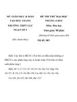
NOTE 1 Connect the point C to the input port, the point D to one of the output ports, and the point G to the other
output port of the device being measured.
NOTE 2
The control bias is supplied to become ON between the point C and G.
Figure 2 – Circuit diagram for the measurement of the isolation L iso
The following description is for the measurement of the isolation between points C and D in
Figure 2. The isolation between points D and G is also able to be measured in the same way.
5.3.3
Isolation
Principle of measurement
Lis o is derived from the input power P i in dBm and the output power P o in dBm of the
device being measured as follows:
L iso = P i – P o
(4)
In the circuit diagram shown in Figure 2, P i and P o are derived from the following equations:
Pi = P1 – L1
Po = P2 + L2
where
P 1 is the value indicated by the power meter 1;
P 2 is the value indicated by the power meter 2;
L 1 is the power at the point B in dBm, less the power at the point C in dBm;
L 2 is the power at the point D in dBm, less the power at the point E in dBm.
P i , P o , P 1 and P 2 are expressed in dBm. L iso , L 1 , and L 2 are expressed in dB.
5.3.4
Circuit description and requirements
See the circuit description and requirements described in 5.2.4.
(5)
(6)
Copyrighted material licensed to BR Demo by Thomson Reuters (Scientific), Inc., subscriptions.techstreet.com, downloaded on Nov-28-2014 by James Madison. No further reproduction or distribution is permitted. Uncontrolled when printe
– 16 –
5.3.5
– 17 –
Precautions to be observed
Harmonics or spurious responses of the signal generator should be reduced to be negligible.
Isolation L iso shall be measured without the influence at the input and output ports.
5.3.6
Measurement procedure
The frequency of the signal generator shall be set to the specified value.
The bias under specified conditions shall be is applied to the device being measured.
An adequate input power shall be applied to the device being measured.
By varying the input power, confirm the change of the output power in dBm is the same as
that of the input power.
The value P 1 is measured at the power meter 1.
The value P 2 is measured at the power meter 2.
The isolation is calculated from Equations (5), (6) and (4).
5.3.7
Specified conditions
–
Ambient or reference-point temperature
–
Bias conditions
–
Frequency.
5.4
5.4.1
Return loss (L ret )
Purpose
To measure the return loss under specified conditions.
5.4.2
Circuit diagram
Signal
generator
Gf
Variable
attenuator
Isolator
Termination
dB
f
Termination
Frequency
meter
C Device being
measured
A
B
W
Power
meter 1
D
W
Termination
Termination
Termination
Power
meter 2
V
V
A
Bias
supply
A
Control
supply
IEC 1020/04
NOTE 1
Connect point C to the port to be measured and terminate the other ports of the device being measured.
NOTE 2
The control bias is supplied to become ON or OFF for the port to be measured.
Figure 3 – Circuit for the measurements of the return loss
Copyrighted material licensed to BR Demo by Thomson Reuters (Scientific), Inc., subscriptions.techstreet.com, downloaded on Nov-28-2014 by James Madison. No further reproduction or distribution is permitted. Uncontrolled when printe
60747-16-4 IEC:2004+A1:2009
5.4.3
60747-16-4 IEC:2004+A1:2009
Principle of measurement
The return loss L ret (dB) is derived from the following equation:
L ret = |P 1 – P 2 |
L ret = P 1 – P 2
(7)
In the circuit diagram shown in Figure 3, the input power is derived from the following
equation:
Pi = Pa – L1
(8)
where
P 1 is the value indicated by the power meter 2 when the point C is either short-circuited or
made open-circuit;
P 2 is the value indicated by the power meter 2 when the device being measured is inserted;
P i is the input power at the point C;
P a is the value indicated by the power meter 1;
L 1 is the power at the point B, less the power at the point C.
P 1 , P 2 , P i and P a are expressed in dBm, L ret and L 1 are expressed in dB.
5.4.4
Circuit description and requirements
The purpose of the isolator is to enable the power level to the device being measured to be
kept constant irrespective of impedance mismatches at its input. The value of L 1 should be
measured beforehand.
5.4.5
Precautions to be observed
See the precautions to be observed of 5.2.5.
5.4.6
Measurement procedure
The point C is either short-circuited or made open-circuit.
The frequency of the signal generator shall be set to the specified value.
An adequate input power shall be applied to the device being measured.
By varying the input power, confirm the change of the output power in dBm is the same as
that of the input power.
The power P 1 is measured by the power meter 2.
The specified port of the device being measured is connected with the point C.
The bias under specified conditions is su applied.
The power P 2 is measured by the power meter 2.
The return loss L ret is calculated from Equation (7).
Copyrighted material licensed to BR Demo by Thomson Reuters (Scientific), Inc., subscriptions.techstreet.com, downloaded on Nov-28-2014 by James Madison. No further reproduction or distribution is permitted. Uncontrolled when printe
– 18 –