Iec 60747 16 5 2013
Bạn đang xem bản rút gọn của tài liệu. Xem và tải ngay bản đầy đủ của tài liệu tại đây (700.34 KB, 86 trang )
®
Edition 1.0 2013-06
INTERNATIONAL
STANDARD
NORME
INTERNATIONALE
Semiconductor devices –
Part 16-5: Microwave integrated circuits – Oscillators
IEC 60747-16-5:2013
Dispositifs à semiconducteurs –
Partie 16-5: Circuits intégrés hyperfréquences – Oscillateurs
Copyrighted material licensed to BR Demo by Thomson Reuters (Scientific), Inc., subscriptions.techstreet.com, downloaded on Nov-27-2014 by James Madison. No further reproduction or distribution is permitted. Uncontrolled when printe
IEC 60747-16-5
All rights reserved. Unless otherwise specified, no part of this publication may be reproduced or utilized in any form
or by any means, electronic or mechanical, including photocopying and microfilm, without permission in writing from
either IEC or IEC's member National Committee in the country of the requester.
If you have any questions about IEC copyright or have an enquiry about obtaining additional rights to this publication,
please contact the address below or your local IEC member National Committee for further information.
Droits de reproduction réservés. Sauf indication contraire, aucune partie de cette publication ne peut être reproduite ni
utilisée sous quelque forme que ce soit et par aucun procédé, électronique ou mécanique, y compris la photocopie et les
microfilms, sans l'accord écrit de la CEI ou du Comité national de la CEI du pays du demandeur.
Si vous avez des questions sur le copyright de la CEI ou si vous désirez obtenir des droits supplémentaires sur cette
publication, utilisez les coordonnées ci-après ou contactez le Comité national de la CEI de votre pays de résidence.
IEC Central Office
3, rue de Varembé
CH-1211 Geneva 20
Switzerland
Tel.: +41 22 919 02 11
Fax: +41 22 919 03 00
www.iec.ch
About the IEC
The International Electrotechnical Commission (IEC) is the leading global organization that prepares and publishes
International Standards for all electrical, electronic and related technologies.
About IEC publications
The technical content of IEC publications is kept under constant review by the IEC. Please make sure that you have the
latest edition, a corrigenda or an amendment might have been published.
Useful links:
IEC publications search - www.iec.ch/searchpub
Electropedia - www.electropedia.org
The advanced search enables you to find IEC publications
by a variety of criteria (reference number, text, technical
committee,…).
It also gives information on projects, replaced and
withdrawn publications.
The world's leading online dictionary of electronic and
electrical terms containing more than 30 000 terms and
definitions in English and French, with equivalent terms in
additional languages. Also known as the International
Electrotechnical Vocabulary (IEV) on-line.
IEC Just Published - webstore.iec.ch/justpublished
Customer Service Centre - webstore.iec.ch/csc
Stay up to date on all new IEC publications. Just Published
details all new publications released. Available on-line and
also once a month by email.
If you wish to give us your feedback on this publication
or need further assistance, please contact the
Customer Service Centre:
A propos de la CEI
La Commission Electrotechnique Internationale (CEI) est la première organisation mondiale qui élabore et publie des
Normes internationales pour tout ce qui a trait à l'électricité, à l'électronique et aux technologies apparentées.
A propos des publications CEI
Le contenu technique des publications de la CEI est constamment revu. Veuillez vous assurer que vous possédez
l’édition la plus récente, un corrigendum ou amendement peut avoir été publié.
Liens utiles:
Recherche de publications CEI - www.iec.ch/searchpub
Electropedia - www.electropedia.org
La recherche avancée vous permet de trouver des
publications CEI en utilisant différents critères (numéro de
référence, texte, comité d’études,…).
Elle donne aussi des informations sur les projets et les
publications remplacées ou retirées.
Le premier dictionnaire en ligne au monde de termes
électroniques et électriques. Il contient plus de 30 000
termes et définitions en anglais et en franỗais, ainsi que
les termes ộquivalents dans les langues additionnelles.
Egalement
appelé
Vocabulaire
Electrotechnique
International (VEI) en ligne.
Just Published CEI - webstore.iec.ch/justpublished
Restez informé sur les nouvelles publications de la CEI.
Just Published détaille les nouvelles publications parues.
Disponible en ligne et aussi une fois par mois par email.
Service Clients - webstore.iec.ch/csc
Si vous désirez nous donner des commentaires sur
cette publication ou si vous avez des questions
contactez-nous:
Copyrighted material licensed to BR Demo by Thomson Reuters (Scientific), Inc., subscriptions.techstreet.com, downloaded on Nov-27-2014 by James Madison. No further reproduction or distribution is permitted. Uncontrolled when printe
THIS PUBLICATION IS COPYRIGHT PROTECTED
Copyright © 2013 IEC, Geneva, Switzerland
®
Edition 1.0 2013-06
INTERNATIONAL
STANDARD
NORME
INTERNATIONALE
Semiconductor devices –
Part 16-5: Microwave integrated circuits – Oscillators
Dispositifs à semiconducteurs –
Partie 16-5: Circuits intégrés hyperfréquences – Oscillateurs
INTERNATIONAL
ELECTROTECHNICAL
COMMISSION
COMMISSION
ELECTROTECHNIQUE
INTERNATIONALE
PRICE CODE
CODE PRIX
ICS 31.080.99
X
ISBN 978-2-83220-827-4
Warning! Make sure that you obtained this publication from an authorized distributor.
Attention! Veuillez vous assurer que vous avez obtenu cette publication via un distributeur agréé.
® Registered trademark of the International Electrotechnical Commission
Marque déposée de la Commission Electrotechnique Internationale
Copyrighted material licensed to BR Demo by Thomson Reuters (Scientific), Inc., subscriptions.techstreet.com, downloaded on Nov-27-2014 by James Madison. No further reproduction or distribution is permitted. Uncontrolled when printe
IEC 60747-16-5
60747-16-5 IEC:2013
CONTENTS
FOREWORD ........................................................................................................................... 6
1
Scope ............................................................................................................................... 8
2
Normative references ....................................................................................................... 8
3
Terms and definitions ....................................................................................................... 8
4
Essential ratings and characteristics ............................................................................... 11
4.1
5
General requirements ............................................................................................ 11
4.1.1 Circuit identification and types ................................................................... 11
4.1.2 General function description ...................................................................... 11
4.1.3 Manufacturing technology .......................................................................... 11
4.1.4 Package identification ................................................................................ 11
4.2 Application description .......................................................................................... 11
4.2.1 Conformance to system and/or interface information ................................. 11
4.2.2 Overall block diagram ................................................................................ 11
4.2.3 Reference data .......................................................................................... 11
4.2.4 Electrical compatibility ............................................................................... 12
4.2.5 Associated devices .................................................................................... 12
4.3 Specification of the function .................................................................................. 12
4.3.1 Detailed block diagram – Functional blocks ............................................... 12
4.3.2 Identification and function of terminals ....................................................... 12
4.3.3 Function description .................................................................................. 13
4.4 Limiting values (absolute maximum rating system) ................................................ 13
4.4.1 Requirements ............................................................................................ 13
4.4.2 Electrical limiting values ............................................................................ 14
4.4.3 Temperatures ............................................................................................ 14
4.5 Operating conditions (within the specified operating temperature range) ............... 15
4.6 Electrical characteristics ........................................................................................ 15
4.7 Mechanical and environmental ratings, characteristics and data ............................ 16
4.8 Additional information ............................................................................................ 16
Measuring methods ........................................................................................................ 16
5.1
5.2
5.3
General ................................................................................................................. 16
5.1.1 General precautions .................................................................................. 16
5.1.2 Characteristic impedance .......................................................................... 17
5.1.3 Handling precautions ................................................................................. 17
5.1.4 Types ........................................................................................................ 17
Oscillation frequency (f osc ) ................................................................................... 17
5.2.1 Purpose ..................................................................................................... 17
5.2.2 Circuit diagram .......................................................................................... 17
5.2.3 Principle of measurement .......................................................................... 17
5.2.4 Circuit description and requirements .......................................................... 17
5.2.5 Precautions to be observed ....................................................................... 17
5.2.6 Measurement procedure ............................................................................ 18
5.2.7 Specified conditions .................................................................................. 18
Output power (P o,osc ) ........................................................................................... 18
5.3.1 Purpose ..................................................................................................... 18
5.3.2 Circuit diagram .......................................................................................... 18
5.3.3 Principle of measurement .......................................................................... 18
Copyrighted material licensed to BR Demo by Thomson Reuters (Scientific), Inc., subscriptions.techstreet.com, downloaded on Nov-27-2014 by James Madison. No further reproduction or distribution is permitted. Uncontrolled when printe
–2–
5.4
5.5
5.6
5.7
5.8
–3–
5.3.4 Circuit description and requirements .......................................................... 18
5.3.5 Precautions to be observed ....................................................................... 18
5.3.6 Measurement procedure ............................................................................ 18
5.3.7 Specified conditions .................................................................................. 18
Phase noise ( L (f)) ................................................................................................ 19
5.4.1 Purpose ..................................................................................................... 19
5.4.2 Measuring methods ................................................................................... 19
Tuning sensitivity (S f,v ) .......................................................................................... 24
5.5.1 Purpose ..................................................................................................... 24
5.5.2 Circuit diagram .......................................................................................... 24
5.5.3 Principle of measurement .......................................................................... 24
5.5.4 Circuit description and requirements .......................................................... 24
5.5.5 Precautions to be observed ....................................................................... 24
5.5.6 Measurement procedure ............................................................................ 24
5.5.7 Specified conditions .................................................................................. 24
Frequency pushing (f osc,push ) .............................................................................. 24
5.6.1 Purpose ..................................................................................................... 24
5.6.2 Circuit diagram .......................................................................................... 25
5.6.3 Principle of measurement .......................................................................... 25
5.6.4 Circuit description and requirements .......................................................... 25
5.6.5 Precautions to be observed ....................................................................... 25
5.6.6 Measurement procedure ............................................................................ 25
5.6.7 Specified conditions .................................................................................. 25
Frequency pulling (f osc,pull ) .................................................................................. 25
5.7.1 Purpose ..................................................................................................... 25
5.7.2 Circuit diagram .......................................................................................... 25
5.7.3 Principle of measurement .......................................................................... 26
5.7.4 Circuit description and requirements .......................................................... 26
5.7.5 Precautions to be observed ....................................................................... 26
5.7.6 Measurement procedure ............................................................................ 26
5.7.7 Specified conditions .................................................................................. 27
n-th order harmonic distortion ratio (P nth /P 1 ) ........................................................ 27
5.8.1 Purpose ..................................................................................................... 27
5.8.2 Circuit diagram .......................................................................................... 27
5.8.3 Principle of measurement .......................................................................... 27
5.8.4 Circuit description and requirements .......................................................... 27
5.8.5 Measurement procedure ............................................................................ 27
5.8.6 Specified conditions .................................................................................. 27
Output power flatness ( ∆ P o,osc ) ............................................................................ 28
5.9.1 Purpose ..................................................................................................... 28
5.9.2 Circuit diagram .......................................................................................... 28
5.9.3 Principle of measurement .......................................................................... 28
5.9.4 Circuit description and requirements .......................................................... 28
5.9.5 Precautions to be observed ....................................................................... 28
5.9.6 Measurement procedure ............................................................................ 28
5.9.7 Specified conditions .................................................................................. 28
5.10 Tuning linearity ...................................................................................................... 28
5.10.1 Purpose ..................................................................................................... 28
5.10.2 Circuit diagram .......................................................................................... 28
5.9
Copyrighted material licensed to BR Demo by Thomson Reuters (Scientific), Inc., subscriptions.techstreet.com, downloaded on Nov-27-2014 by James Madison. No further reproduction or distribution is permitted. Uncontrolled when printe
60747-16-5 IEC:2013
5.10.3
5.10.4
5.10.5
5.10.6
5.10.7
60747-16-5 IEC:2013
Principle of measurement .......................................................................... 29
Circuit description and requirements .......................................................... 29
Precautions to be observed ....................................................................... 29
Measurement procedure ............................................................................ 29
Specified conditions .................................................................................. 30
5.11 Frequency temperature coefficient ( α f,temp ) ......................................................... 30
5.11.1 Purpose ..................................................................................................... 30
5.11.2 Circuit diagram .......................................................................................... 30
5.11.3 Principle of measurement .......................................................................... 30
5.11.4 Circuit description and requirements .......................................................... 31
5.11.5 Precautions to be observed ....................................................................... 31
5.11.6 Measurement procedure ............................................................................ 31
5.11.7 Specified conditions .................................................................................. 31
6
5.12 Output power temperature coefficient ( α P,temp ).................................................... 31
5.12.1 Purpose ..................................................................................................... 31
5.12.2 Circuit diagram .......................................................................................... 31
5.12.3 Principle of measurement .......................................................................... 31
5.12.4 Circuit description and requirements .......................................................... 32
5.12.5 Precautions to be observed ....................................................................... 32
5.12.6 Measurement procedure ............................................................................ 32
5.12.7 Specified conditions .................................................................................. 32
5.13 Spurious distortion ratio (P s /P 1 ) ............................................................................ 32
5.13.1 Purpose ..................................................................................................... 32
5.13.2 Circuit diagram .......................................................................................... 32
5.13.3 Principle of measurement .......................................................................... 32
5.13.4 Circuit description and requirements .......................................................... 33
5.13.5 Measurement procedure ............................................................................ 33
5.13.6 Specified conditions .................................................................................. 33
5.14 Modulation bandwidth (B mod )................................................................................ 33
5.14.1 Purpose ..................................................................................................... 33
5.14.2 Circuit diagram .......................................................................................... 33
5.14.3 Principle of measurement .......................................................................... 34
5.14.4 Circuit description and requirements .......................................................... 34
5.14.5 Precautions to be observed ....................................................................... 34
5.14.6 Measurement procedure ............................................................................ 34
5.14.7 Specified conditions .................................................................................. 35
5.15 Sensitivity flatness ................................................................................................ 35
5.15.1 Purpose ..................................................................................................... 35
5.15.2 Circuit diagram .......................................................................................... 35
5.15.3 Principle of measurement .......................................................................... 35
5.15.4 Circuit description and requirements .......................................................... 36
5.15.5 Precautions to be observed ....................................................................... 36
5.15.6 Measurement procedure ............................................................................ 36
5.15.7 Specified conditions .................................................................................. 36
Verifying methods ........................................................................................................... 36
6.1
Load mismatch tolerance ( Ψ L ) ............................................................................... 36
6.1.1 Purpose ..................................................................................................... 36
6.1.2 Verifying method 1 (spurious intensity) ...................................................... 36
Copyrighted material licensed to BR Demo by Thomson Reuters (Scientific), Inc., subscriptions.techstreet.com, downloaded on Nov-27-2014 by James Madison. No further reproduction or distribution is permitted. Uncontrolled when printe
–4–
6.1.3
–5–
Verifying method 2 (no discontinuity of frequency tuning
characteristics of VCO) .............................................................................. 37
Load mismatch ruggedness ( Ψ R ) .......................................................................... 38
6.2.1 Purpose ..................................................................................................... 38
6.2.2 Circuit diagram .......................................................................................... 38
6.2.3 Circuit description and requirements .......................................................... 38
6.2.4 Precautions to be observed ....................................................................... 38
6.2.5 Test Procedure .......................................................................................... 38
6.2.6 Specified conditions .................................................................................. 39
Bibliography .......................................................................................................................... 40
6.2
Figure 1 – Circuit diagram for the measurement of the oscillation frequency f osc .................. 17
Figure 2 – Circuit diagram for the measurement of the phase noise L (f) (method 1) ............. 20
Figure 3 – Circuit diagram for the measurement of the phase noise L (f) (method 2) ............. 21
Figure 4 – Circuit diagram for the measurement of the phase noise L (f) (method 3) ............. 22
Figure 5 – Circuit diagram for the measurement of the frequency pulling f osc,pull ................ 26
Figure 6 – Tuning linearity .................................................................................................... 29
Figure 7 – Circuit diagram for the measurement of the oscillation frequency
temperature coefficient α f,temp ............................................................................................ 30
Figure 8 – Circuit diagram for the measurement of the modulation bandwidth B mod ............. 34
Figure 9 – Sensitivity flatness ............................................................................................... 36
Table 1 – Comparison of phase noise measuring methods .................................................... 19
Copyrighted material licensed to BR Demo by Thomson Reuters (Scientific), Inc., subscriptions.techstreet.com, downloaded on Nov-27-2014 by James Madison. No further reproduction or distribution is permitted. Uncontrolled when printe
60747-16-5 IEC:2013
60747-16-5 IEC:2013
INTERNATIONAL ELECTROTECHNICAL COMMISSION
____________
SEMICONDUCTOR DEVICES –
Part 16-5: Microwave integrated circuits –
Oscillators
FOREWORD
1) The International Electrotechnical Commission (IEC) is a worldwide organization for standardization comprising
all national electrotechnical committees (IEC National Committees). The object of IEC is to promote
international co-operation on all questions concerning standardization in the electrical and electronic fields. To
this end and in addition to other activities, IEC publishes International Standards, Technical Specifications,
Technical Reports, Publicly Available Specifications (PAS) and Guides (hereafter referred to as “IEC
Publication(s)”). Their preparation is entrusted to technical committees; any IEC National Committee interested
in the subject dealt with may participate in this preparatory work. International, governmental and nongovernmental organizations liaising with the IEC also participate in this preparation. IEC collaborates closely
with the International Organization for Standardization (ISO) in accordance with conditions determined by
agreement between the two organizations.
2) The formal decisions or agreements of IEC on technical matters express, as nearly as possible, an international
consensus of opinion on the relevant subjects since each technical committee has representation from all
interested IEC National Committees.
3) IEC Publications have the form of recommendations for international use and are accepted by IEC National
Committees in that sense. While all reasonable efforts are made to ensure that the technical content of IEC
Publications is accurate, IEC cannot be held responsible for the way in which they are used or for any
misinterpretation by any end user.
4) In order to promote international uniformity, IEC National Committees undertake to apply IEC Publications
transparently to the maximum extent possible in their national and regional publications. Any divergence
between any IEC Publication and the corresponding national or regional publication shall be clearly indicated in
the latter.
5) IEC itself does not provide any attestation of conformity. Independent certification bodies provide conformity
assessment services and, in some areas, access to IEC marks of conformity. IEC is not responsible for any
services carried out by independent certification bodies.
6) All users should ensure that they have the latest edition of this publication.
7) No liability shall attach to IEC or its directors, employees, servants or agents including individual experts and
members of its technical committees and IEC National Committees for any personal injury, property damage or
other damage of any nature whatsoever, whether direct or indirect, or for costs (including legal fees) and
expenses arising out of the publication, use of, or reliance upon, this IEC Publication or any other IEC
Publications.
8) Attention is drawn to the Normative references cited in this publication. Use of the referenced publications is
indispensable for the correct application of this publication.
9) Attention is drawn to the possibility that some of the elements of this IEC Publication may be the subject of
patent rights. IEC shall not be held responsible for identifying any or all such patent rights.
International Standard IEC 60747-16-5 has been prepared by subcommittee 47E: Discrete
semiconductor devices, of IEC technical committee 47: Semiconductor devices.
The text of this standard is based on the following documents:
FDIS
Report on voting
47E/452/FDIS
47E/454/RVD
Full information on the voting for the approval of this standard can be found in the report on
voting indicated in the above table.
This publication has been drafted in accordance with the ISO/IEC Directives, Part 2.
A list of all parts of the IEC 60747 series, published under the general title Semiconductor
devices, can be found on the IEC website.
Copyrighted material licensed to BR Demo by Thomson Reuters (Scientific), Inc., subscriptions.techstreet.com, downloaded on Nov-27-2014 by James Madison. No further reproduction or distribution is permitted. Uncontrolled when printe
–6–
–7–
The committee has decided that the contents of this publication will remain unchanged until
the stability date indicated on the IEC web site under "" in the data
related to the specific publication. At this date, the publication will be
•
•
•
•
reconfirmed,
withdrawn,
replaced by a revised edition, or
amended.
Copyrighted material licensed to BR Demo by Thomson Reuters (Scientific), Inc., subscriptions.techstreet.com, downloaded on Nov-27-2014 by James Madison. No further reproduction or distribution is permitted. Uncontrolled when printe
60747-16-5 IEC:2013
60747-16-5 IEC:2013
SEMICONDUCTOR DEVICES –
Part 16-5: Microwave integrated circuits –
Oscillators
1
Scope
This part of IEC 60747 specifies the terminology, essential ratings and characteristics, and
measuring methods of microwave integrated circuit oscillators.
This standard is applicable to the fixed and voltage-controlled semiconductor microwave
oscillator devices, except the oscillator modules such as synthesizers which require external
controllers.
NOTE This document is not applicable to the quartz crystal controlled oscillators. They are specified by
IEC 60679-1.
2
Normative references
The following documents, in whole or in part, are normatively referenced in this document and
are indispensable for its application. For dated references, only the edition cited applies. For
undated references, the latest edition of the referenced document (including any
amendments) applies.
IEC 60617, Graphical symbols for diagrams (available from < />IEC 60747-1:2006, Semiconductor devices – Part 1: General 1)
Amendment 1:2010
IEC 60747-4:2007, Semiconductor devices – Discrete devices – Part 4: Microwave diodes and
transistors
IEC 60747-16-3:2002, Semiconductor devices – Part 16-3: Microwave integrated circuits –
)
Frequency converters 2
Amendment 1:2009
IEC 61340-5-1, Electrostatics – Part 5-1: Protection of electronic devices from electrostatic
phenomena – General requirements
IEC/TR 61340-5-2, Electrostatics – Part
electrostatic phenomena – User guide
3
5-2:
Protection
of
electronic
Terms and definitions
3.1
oscillation frequency
f osc
frequency measured at the output port
___________
1) A consolidated edition (2010) exists, including IEC 60747-1:2006 and its Amendment 1.
2) A consolidated edition (2010) exists, including IEC 60747-16-3:2002 and its Amendment 1.
devices
from
Copyrighted material licensed to BR Demo by Thomson Reuters (Scientific), Inc., subscriptions.techstreet.com, downloaded on Nov-27-2014 by James Madison. No further reproduction or distribution is permitted. Uncontrolled when printe
–8–
–9–
3.2
output power
P o,osc
power measured at the output port
3.3
phase noise
L (f)
frequency-domain measure of the short-term frequency stability of an oscillator, normally
expressed as the power spectral density of the phase fluctuations, S φ (f), where the phase
fluctuation function is φ(t) = 2π Ft-2πF 0 t
Note 1 to entry: The spectral density of phase fluctuation can be directly related to the spectral density of
frequency fluctuation by
F
S φ ( f ) = 0
f
2
S y ( f ) rad 2 / Hz
where
F
is the oscillator frequency;
F0
is the average oscillator frequency;
f
is the Fourier frequency.
Note 2 to entry:
L (f) is pronounced "script-ell of f".
[SOURCE: IEC 60679-1:2007, 3.2.25, modified – A symbol and two notes have been added.
The explanation of the spectral density of phase fluctuation has been moved to a note]
3.4
tuning sensitivity
S f,v
ratio of the change of oscillation frequency to the variation of the control voltage
3.5
frequency pushing
f osc,push
change of the oscillation frequency with the variation of the bias voltage
3.6
frequency pulling
f osc,pull
change of the oscillation frequency with all phase angles for constant load reflection
coefficient
3.7
n-th order harmonic distortion ratio
P nth /P 1
ratio of the power of the n-th order harmonic component at the output port to the output power
at the oscillation frequency
3.8
oscillation frequency range
difference between the oscillation frequencies at the maximum control voltage and at the
minimum control voltage
Copyrighted material licensed to BR Demo by Thomson Reuters (Scientific), Inc., subscriptions.techstreet.com, downloaded on Nov-27-2014 by James Madison. No further reproduction or distribution is permitted. Uncontrolled when printe
60747-16-5 IEC:2013
60747-16-5 IEC:2013
3.9
output power flatness
∆ P o,osc
difference between the maximum and the minimum output power within the control voltage
range
3.10
tuning linearity
ratio of the maximum departure of the oscillation frequency from an ideal straight line between
its values at the minimum and maximum control voltages to the oscillation frequency range
3.11
oscillation frequency temperature coefficient
α f,temp
ratio of the change in oscillation frequency to the corresponding change in temperature
3.12
output power temperature coefficient
α P,temp
ratio of the change in output power to the corresponding change in temperature
3.13
spurious distortion ratio
P s /P 1
ratio of the power of the maximum spurious component at the output port to the output power
at the oscillation frequency
3.14
load mismatch tolerance
ΨL
maximum load VSWR (voltage standing-wave ratio) in the range where the device oscillates
with no unexpected spurious intensity and/or no discontinuity of frequency tuning
characteristics (in case of VCO) at all phase angles
3.15
load mismatch ruggedness
ΨR
maximum load VSWR in the range where the device withstand load mismatch with no
degradation at all phase angles with specified conditions
[SOURCE: IEC 60747-4:2007, 7.2.22]
3.16
modulation bandwidth
B mod
modulating frequency at which the frequency deviation decreases by 3 dB from its dc value
3.17
sensitivity flatness
ratio of the maximum departure of the tuning sensitivity from an ideal straight line between its
values at the minimum and maximum control voltages to the oscillation frequency range
Copyrighted material licensed to BR Demo by Thomson Reuters (Scientific), Inc., subscriptions.techstreet.com, downloaded on Nov-27-2014 by James Madison. No further reproduction or distribution is permitted. Uncontrolled when printe
– 10 –
4
– 11 –
Essential ratings and characteristics
4.1
General requirements
4.1.1
Circuit identification and types
The identification of type (device name), the category of circuit and technology applied shall
be given.
Microwave oscillators are divided into two categories:
–
type A: fixed oscillator;
–
type B: voltage controlled oscillator.
4.1.2
General function description
A general description of the function performed by the integrated circuit microwave oscillators
and the features for the application shall be made.
4.1.3
Manufacturing technology
The manufacturing technology, e.g. semiconductor monolithic integrated circuit, thin film
integrated circuit, micro-assembly, etc. shall be stated. This statement shall include details of
the semiconductor technologies such as Schottky barrier diode, MESFET, Si bipolar transistor,
etc.
IEC 60747-4 shall be referred to for terminology and letter symbols, essential ratings and
characteristics and measuring methods of such microwave devices.
4.1.4
Package identification
The following statements shall be made:
a) chip or packaged form;
b) IEC and/or national reference number of the outline drawing, or drawing of non-standard
package including terminal numbering;
c) principal package material, for example, metal, ceramic, plastic.
4.2
4.2.1
Application description
Conformance to system and/or interface information
It should be stated whether the integrated circuit conforms to an application system and/or an
interface standard or a recommendation.
Detailed information concerning application systems, equipment and circuits such as very
small aperture terminal (VSAT) systems, broadcasting satellite (BS) receivers, microwave
landing systems, etc. should also be given.
4.2.2
Overall block diagram
A block diagram of the applied systems should be given if necessary.
4.2.3
Reference data
The most important properties that permit comparison between derivative types should be
given.
Copyrighted material licensed to BR Demo by Thomson Reuters (Scientific), Inc., subscriptions.techstreet.com, downloaded on Nov-27-2014 by James Madison. No further reproduction or distribution is permitted. Uncontrolled when printe
60747-16-5 IEC:2013
4.2.4
60747-16-5 IEC:2013
Electrical compatibility
It should be stated whether the integrated circuit is electrically compatible with other particular
integrated circuits, or families of integrated circuits, or whether special interfaces are required.
Details should be given concerning the type of output circuits, e.g. output impedances, d.c.
block, open-drain, etc. Interchangeability with other devices, if any, should also be given.
4.2.5
Associated devices
If applicable, the following should be stated:
–
devices necessary for correct operation (list with type number, name and function);
–
peripheral devices with direct interfacing (list with type number, name and function).
4.3
Specification of the function
4.3.1
Detailed block diagram – Functional blocks
A detail block diagram or equivalent circuit information of the integrated circuit microwave
oscillators shall be given. The block diagram shall be composed of the following:
a) functional blocks;
b) mutual interconnections among the functional blocks;
c) individual functional units within the functional blocks;
d) mutual interconnections among the individual functional blocks;
e) function of each external connection;
f)
inter-dependence between the separate functional blocks.
The block diagram shall identify the function of each external connection and, where no
ambiguity can arise, also show the terminal symbols and/or numbers. If the encapsulation has
metallic parts, any connection to them from external terminals shall be indicated. The
connections with any associated external electrical elements shall be stated, where necessary.
As additional information, the complete electrical circuit diagram can be reproduced, but not
necessarily with indications of the values of the circuit components. The graphical symbol for
the function shall be given. Rules governing such diagrams may be obtained from IEC 60617.
4.3.2
Identification and function of terminals
All terminals shall be identified on the block diagram (supply terminals, output terminals).
The terminal functions 1) to 4) shall be indicated in a table as follows:
Function of terminal
Terminal
number
Terminal
symbol
1) Terminal
designation
2) Function
3) Output
identification
4) Type of
output circuits
(1) Terminal designation
A terminal designation to indicate the function of the terminal shall be given. Supply
terminals, ground terminals, blank terminals (with abbreviation NC), non-usable terminals
(with abbreviation NU) shall be distinguished.
(2) Function
A brief indication of the terminal function shall be given:
–
each function of multi-role terminals, i.e. terminals having multiple functions;
Copyrighted material licensed to BR Demo by Thomson Reuters (Scientific), Inc., subscriptions.techstreet.com, downloaded on Nov-27-2014 by James Madison. No further reproduction or distribution is permitted. Uncontrolled when printe
– 12 –
–
– 13 –
each function of integrated circuit selected by mutual pin connections, programming
and/or application of function selection data to the function selection pin, such as
mode selection pin.
(3) Output identification
Output and multiplex output terminals shall be distinguished.
(4) Type of output circuits
The type of output circuit, e.g. output impedances, with or without d.c. block, etc., shall be
distinguished.
If the baseplate of the package is used as a ground terminal, the type of ground, e.g. analog
ground, digital ground, shall be stated in the column of 2) Function.
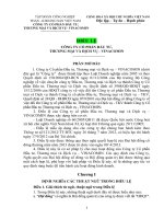
EXAMPLE
Bias voltage(s)
NC
NU
Control voltage(s)
Integrated
circuit
microwave
oscillator
NC
Output(s)
Ground
4.3.3
IEC 1332/13
Function description
The function performed by the circuit shall be specified, including the following information:
–
basic function;
–
relation to external terminals;
–
operation mode (e.g., set-up method, preference, etc.).
4.4
Limiting values (absolute maximum rating system)
4.4.1
Requirements
The table for these values shall contain the following:
–
Any interdependence of limiting conditions shall be specified.
–
If externally connected and/or attached elements, for example heatsinks, have an
influence on the values of the ratings, the ratings shall be prescribed for the integrated
circuit with the elements connected and/or attached.
–
If limiting values are exceeded for transient overload, the permissible excess and their
durations shall be specified.
–
Where minimum and maximum values differ during programming of the device, this shall
be stated.
–
All voltages are referenced to a specified reference terminal (V ss , ground, etc.).
–
In satisfying the following clauses, if maximum and/or minimum values are quoted, the
manufacturer shall indicate whether he refers to the absolute magnitude or to the
algebraic value of the quantity.
Copyrighted material licensed to BR Demo by Thomson Reuters (Scientific), Inc., subscriptions.techstreet.com, downloaded on Nov-27-2014 by James Madison. No further reproduction or distribution is permitted. Uncontrolled when printe
60747-16-5 IEC:2013
–
60747-16-5 IEC:2013
The ratings given shall cover the operation of the multi-function integrated circuit over the
specified range of operating temperatures. Where such ratings are temperature-dependent,
these dependence shall be indicated.
4.4.2
Electrical limiting values
Limiting values shall be specified as follows:
Parameters
Min.
Max.
Bias voltage(s) (where appropriate)
+
Bias current(s) (where appropriate)
+
Control voltage(s) (where appropriate)
+
Control current(s) (where appropriate)
+
Terminal voltage(s) (where appropriate)
+
+
Terminal current(s) (where appropriate)
+
Power dissipation
+
It is necessary to select either Bias voltage(s) or Bias current(s), either Control voltage(s) or
Control current(s), and either Terminal voltage(s) or Terminal current(s).
The detail specification may indicate those values within the table including footnotes a and b.
Parameters a, b
a
4.4.3
Symbols
Min.
Max.
Unit
Where appropriate, in accordance with the type of circuit considered.
b
For power supply voltage range:
–
limiting value(s) of the continuous voltage(s) at the supply terminal(s) with respect to a
special electrical reference point;
–
where appropriate, limiting value between specified supply terminals;
–
when more than one voltage supply is required, a statement shall be made as to whether
the sequence in which these supplies are applied is significant: if so, the sequence shall
be stated;
–
when more than one supply is needed, it may be necessary to state the combinations of
ratings for these supply voltages and currents.
Temperatures
a) Operating temperature (ambient or reference-point temperature)
b) Storage temperature
c) Channel temperature
d) Lead temperature (for soldering)
The detail specification may indicate those values within the table including the note.
Parameters (Note)
NOTE
Symbols
Min.
Max.
Where appropriate, in accordance with the type of circuit considered.
Unit
Copyrighted material licensed to BR Demo by Thomson Reuters (Scientific), Inc., subscriptions.techstreet.com, downloaded on Nov-27-2014 by James Madison. No further reproduction or distribution is permitted. Uncontrolled when printe
– 14 –
4.5
– 15 –
Operating conditions (within the specified operating temperature range)
Operating conditions are not to be inspected, but may be used for quality assessment
purpose.
a) Power supplies – Positive and/or negative values
b) Initialization sequences (where appropriate)
If special initialization sequences are necessary, power supply sequencing and initialization
procedure shall be specified.
c) Input voltage(s) (where appropriate)
d) Output current(s) (where appropriate)
e) Voltage and/or current of other terminal(s)
f)
External elements (where appropriate)
g) Operating temperature range
4.6
Electrical characteristics
The characteristics shall apply over the full operating temperature range, unless otherwise
specified. Each characteristic shall be stated either:
a) over the specified range of operating temperatures, or
b) at a temperature of 25 °C, and at maximum and minimum operating temperatures.
Parameters
Min.
Typ.
Max.
Bias operating current
+
+
Control operating current
+
+
Types
A
B
+
+
+
Oscillation frequency, f osc
+
+
+
+
+
Output power, P o,osc
+
+
+
+
+
+
+
+
Phase noise, L (f)
Tuning sensitivity, S f,v
+
+
+
Frequency pushing, f osc,push
+
+
+
Frequency pulling, f osc,pull
+
+
+
n-th order harmonic distortion ratio,
P nth /P 1
+
+
+
Oscillation frequency range
+
+
+
Output power flatness, ∆ P o,osc
+
+
+
Tuning linearity
+
+
+
Oscillation frequency temperature
coefficient, α f,temp
+
+
+
+
Output power temperature
coefficient, α P,temp
+
+
+
+
+
+
+
Spurious distortion ratio, P s /P 1
Copyrighted material licensed to BR Demo by Thomson Reuters (Scientific), Inc., subscriptions.techstreet.com, downloaded on Nov-27-2014 by James Madison. No further reproduction or distribution is permitted. Uncontrolled when printe
60747-16-5 IEC:2013
Parameters
Min.
60747-16-5 IEC:2013
Typ.
Max.
Load mismatch tolerance, Ψ L
Types
A
B
+
+
+
+
+
+
(where appropriate)
Load mismatch ruggedness, Ψ R
(where appropriate)
Modulation bandwidth, B mod
+
+
(where appropriate)
Sensitivity flatness
+
+
(where appropriate)
4.7
Mechanical and environmental ratings, characteristics and data
Any specific mechanical and environmental ratings applicable shall be stated (see also 5.10
and 5.11 of IEC 60747-1:2006).
4.8
Additional information
Where appropriate, the following information shall be given:
a) Equivalent output circuit: Detail information shall be given regarding the type of output
circuits, e.g. output impedances, d.c. block, open-drain, etc.
b) Internal protection: A statement shall be given to indicate whether the integrated circuit
contains internal protection against high static voltages or electrical fields.
c) Capacitors at terminals: If capacitors for the output d.c. block are needed, these
capacitances shall be stated.
d) Thermal resistance;
e) Interconnections to other types of circuit:
interconnections to other circuits shall be given.
f)
Where
appropriate,
details
of
the
Effects of externally connected component(s): Curves or data indicating the effect of
externally connected component(s) that influence the characteristics may be given.
g) Recommendations for any associated device(s): For example, decoupling of power supply
to a high-frequency device shall be stated.
h) Handling precautions: Where appropriate, handling precautions specific to the circuit shall
be stated (see also IEC 61340-5-1 and IEC/TR 61340-5-2).
i)
Application data;
j)
Other application information;
k) Date of issue of the data sheet.
5
Measuring methods
5.1
5.1.1
General
General precautions
The general precautions listed in 6.3, 6.4 and 6.6 of IEC 60747-1:2006 shall be applied. In
addition, special care shall be taken to use low-ripple dc power supplies and to decouple
adequately all supply terminals at the frequency of measurement. Although the level of the
signal can be specified in either power or voltage, in this standard it is expressed in power
unless otherwise specified.
Copyrighted material licensed to BR Demo by Thomson Reuters (Scientific), Inc., subscriptions.techstreet.com, downloaded on Nov-27-2014 by James Madison. No further reproduction or distribution is permitted. Uncontrolled when printe
– 16 –
5.1.2
– 17 –
Characteristic impedance
The characteristic impedance of the measurement system, shown in the circuit in this
standard, is 50 Ω. If it is not 50 Ω, it shall be specified.
5.1.3
Handling precautions
When handling electrostatic-sensitive devices, the
IEC 61340-5-1 and IEC/TR 61340-5-2 shall be observed.
5.1.4
handling
precautions
given
in
Types
The devices in this standard are both packaged and chip types, measured using suitable test
fixtures.
Oscillation frequency (f osc )
5.2
5.2.1
Purpose
To measure the oscillation frequency under specified conditions.
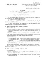
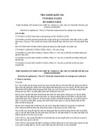
5.2.2
Circuit diagram
The measuring circuit is shown in Figure 1.
Device being
measured
Attenuator
A
Directional
coupler
A
Power meter
B
W
V
V
A
Hz
A
Bias
voltage
Control
voltage
Frequency
meter
or
spectrum
analyser
IEC 1333/13
NOTE
The device being measured can contain a resonance circuit.
Figure 1 – Circuit diagram for the measurement of the oscillation frequency f osc
5.2.3
Principle of measurement
The oscillation frequency is the frequency of the signal generated from the device being
measured under specified bias conditions.
5.2.4
Circuit description and requirements
The purpose of the attenuator is to reduce the change of the oscillation frequency from a
mismatch with oscillator output and load impedance.
5.2.5
Precautions to be observed
Harmonics or spurious responses of the device being measured shall be negligible.
Copyrighted material licensed to BR Demo by Thomson Reuters (Scientific), Inc., subscriptions.techstreet.com, downloaded on Nov-27-2014 by James Madison. No further reproduction or distribution is permitted. Uncontrolled when printe
60747-16-5 IEC:2013
5.2.6
60747-16-5 IEC:2013
Measurement procedure
The bias under specified conditions is supplied.
In case of VCO, the control voltage is set to the specified value.
The value f osc is measured at the frequency meter or spectrum analyser.
5.2.7
Specified conditions
–
Ambient or reference-point temperature
–
Bias conditions
–
In case of VCO, control voltage
Output power (P o,osc )
5.3
5.3.1
Purpose
To measure the output power P o,osc under specified conditions.
5.3.2
Circuit diagram
See the circuit diagram shown in Figure 1.
5.3.3
Principle of measurement
The output power P o,osc of the device being measured is derived from the following equation:
Po,osc = P1 + L1
where
P 1 is the value indicated by power meter in dBm;
L 1 is the insertion loss from the power at point A to the power at the point B in dB.
5.3.4
Circuit description and requirements
See the circuit description and requirements in 5.2.4.
The insertion loss L 1 shall be measured beforehand.
5.3.5
Precautions to be observed
See the precautions to be observed in 5.2.5.
5.3.6
Measurement procedure
The bias under specified conditions is supplied.
In case of VCO, the oscillation frequency is set to the specified value.
The value P 1 is measured by the power meter, then P o,osc is derived from the Equation (1).
5.3.7
Specified conditions
–
Ambient or reference-point temperature
–
Bias conditions
(1)
Copyrighted material licensed to BR Demo by Thomson Reuters (Scientific), Inc., subscriptions.techstreet.com, downloaded on Nov-27-2014 by James Madison. No further reproduction or distribution is permitted. Uncontrolled when printe
– 18 –