Iec 60747 16 10 2004
Bạn đang xem bản rút gọn của tài liệu. Xem và tải ngay bản đầy đủ của tài liệu tại đây (438.61 KB, 62 trang )
INTERNATIONAL
STANDARD
IEC
60747-16-10
QC 210021
First edition
2004-07
Part 16-10:
Technology Approval Schedule (TAS)
for monolithic microwave integrated circuits
Reference number
IEC 60747-16-10:2004(E)
LICENSED TO MECON Limited. - RANCHI/BANGALORE
FOR INTERNAL USE AT THIS LOCATION ONLY, SUPPLIED BY BOOK SUPPLY BUREAU.
Semiconductor devices –
Publication numbering
As from 1 January 1997 all IEC publications are issued with a designation in the
60000 series. For example, IEC 34-1 is now referred to as IEC 60034-1.
Consolidated editions
The IEC is now publishing consolidated versions of its publications. For example,
edition numbers 1.0, 1.1 and 1.2 refer, respectively, to the base publication, the
base publication incorporating amendment 1 and the base publication incorporating
amendments 1 and 2.
Further information on IEC publications
•
IEC Web Site (www.iec.ch)
•
Catalogue of IEC publications
The on-line catalogue on the IEC web site (www.iec.ch/searchpub) enables you to
search by a variety of criteria including text searches, technical committees
and date of publication. On-line information is also available on recently issued
publications, withdrawn and replaced publications, as well as corrigenda.
•
IEC Just Published
This summary of recently issued publications (www.iec.ch/online_news/ justpub)
is also available by email. Please contact the Customer Service Centre (see
below) for further information.
•
Customer Service Centre
If you have any questions regarding this publication or need further assistance,
please contact the Customer Service Centre:
Email:
Tel:
+41 22 919 02 11
Fax: +41 22 919 03 00
LICENSED TO MECON Limited. - RANCHI/BANGALORE
FOR INTERNAL USE AT THIS LOCATION ONLY, SUPPLIED BY BOOK SUPPLY BUREAU.
The technical content of IEC publications is kept under constant review by the IEC,
thus ensuring that the content reflects current technology. Information relating to
this publication, including its validity, is available in the IEC Catalogue of
publications (see below) in addition to new editions, amendments and corrigenda.
Information on the subjects under consideration and work in progress undertaken
by the technical committee which has prepared this publication, as well as the list
of publications issued, is also available from the following:
INTERNATIONAL
STANDARD
IEC
60747-16-10
QC 210021
First edition
2004-07
LICENSED TO MECON Limited. - RANCHI/BANGALORE
FOR INTERNAL USE AT THIS LOCATION ONLY, SUPPLIED BY BOOK SUPPLY BUREAU.
Semiconductor devices –
Part 16-10:
Technology Approval Schedule (TAS)
for monolithic microwave integrated circuits
© IEC 2004 ⎯ Copyright - all rights reserved
No part of this publication may be reproduced or utilized in any form or by any means, electronic or
mechanical, including photocopying and microfilm, without permission in writing from the publisher.
International Electrotechnical Commission, 3, rue de Varembé, PO Box 131, CH-1211 Geneva 20, Switzerland
Telephone: +41 22 919 02 11 Telefax: +41 22 919 03 00 E-mail: Web: www.iec.ch
Com mission Electrotechnique Internationale
International Electrotechnical Com m ission
Ɇɟɠɞɭɧɚɪɨɞɧɚɹ ɗɥɟɤɬɪɨɬɟɯɧɢɱɟɫɤɚɹ Ʉɨɦɢɫɫɢɹ
PRICE CODE
XA
For price, see current catalogue
–2–
60747-16-10 © IEC:2004(E)
CONTENTS
FOREWORD...........................................................................................................................4
Foreword to this particular Technology Approval Schedule (TAS) ...........................................7
Organizations responsible for preparing the present TAS........................................................7
Preface ...................................................................................................................................7
INTRODUCTION.....................................................................................................................8
General ............................................................................................................................9
2
1.1 Scope......................................................................................................................9
1.2 Normative documents ..............................................................................................9
1.3 Units, symbols and terminology ............................................................................. 10
1.4 Standard and preferred values .............................................................................. 10
1.5 Definitions ............................................................................................................. 10
Definition of the component technology .......................................................................... 12
3
2.1 Scope.................................................................................................................... 12
2.2 Description of activities and flow charts ................................................................. 13
2.3 Technical abstract ................................................................................................. 13
2.4 Requirements for control of subcontractors ........................................................... 16
Component design of MMICs .......................................................................................... 18
4
3.1
3.2
3.3
3.4
Mask
5
4.1 Scope.................................................................................................................... 23
4.2 Description of activities and flow charts ................................................................. 23
4.3 Validation and control of the processes ................................................................. 23
4.4 Subcontractors, vendors and internal suppliers ..................................................... 23
Wafer fabrication of MMICs ............................................................................................ 23
6
5.1 Scope.................................................................................................................... 23
5.2 Description of activities and flow charts ................................................................. 24
5.3 Equipment ............................................................................................................. 26
5.4 Materials ............................................................................................................... 26
5.5 Re-work ................................................................................................................ 26
5.6 Validation methods and control of the processes ................................................... 27
5.7 Interrelationship .................................................................................................... 28
Wafer probing of MMICs ................................................................................................. 30
7
6.1 Scope.................................................................................................................... 30
6.2 Description of activities and flow charts ................................................................. 30
6.3 Equipment ............................................................................................................. 30
6.4 Test procedures .................................................................................................... 30
6.5 Interrelationship .................................................................................................... 30
Back-side process for bare chip delivery ........................................................................ 32
7.1
7.2
7.3
7.4
Scope.................................................................................................................... 18
Description of activities and flow charts ................................................................. 18
Interfaces .............................................................................................................. 19
Validations and control of the processes ............................................................... 21
manufacture .......................................................................................................... 23
Scope.................................................................................................................... 32
Description of activity and flow charts.................................................................... 32
Equipment ............................................................................................................. 33
Materials ............................................................................................................... 33
LICENSED TO MECON Limited. - RANCHI/BANGALORE
FOR INTERNAL USE AT THIS LOCATION ONLY, SUPPLIED BY BOOK SUPPLY BUREAU.
1
60747-16-10 © IEC:2004(E)
–3–
8
7.5 Validation methods and control of the processes ................................................... 33
7.6 Interrelationship .................................................................................................... 33
7.7 Validity of release.................................................................................................. 34
Assembly of MMICs ........................................................................................................ 36
9
8.1 Scope.................................................................................................................... 36
8.2 Description of activities and flow charts ................................................................. 36
8.3 Materials, inspection and handling......................................................................... 37
8.4 Equipment ............................................................................................................. 37
8.5 Re-work ................................................................................................................ 37
8.6 Validation and control of the processes ................................................................. 37
8.7 Interrelationships................................................................................................... 38
Testing of MMICs ........................................................................................................... 40
10.1 Identification of process characteristics ................................................................. 50
10.2 Description of activities ......................................................................................... 51
10.3 Characterization procedures.................................................................................. 52
11 Packaging and shipping.................................................................................................. 53
11.1 Description of activities and flow charts ................................................................. 53
11.2 Interfaces .............................................................................................................. 54
11.3 Validity of release.................................................................................................. 54
12 Withdrawal of Technology Approval ................................................................................ 56
Figure 1 – Example flow chart of design/manufacture/test..................................................... 16
Figure 2 – Example flow chart of a design............................................................................. 21
Figure 3 – Technology flow chart of the process ................................................................... 29
Figure 4 – Example flow chart for a wafer probing. ............................................................... 30
Figure 5 – Example flow chart for a back-side process for bare chip delivery ........................ 34
Figure 6 – Example flow chart for an assembly ..................................................................... 38
Figure 7 – Example flow char for a testing ............................................................................ 44
Figure 8 – Typical flow chart for packaging and shipping ...................................................... 54
LICENSED TO MECON Limited. - RANCHI/BANGALORE
FOR INTERNAL USE AT THIS LOCATION ONLY, SUPPLIED BY BOOK SUPPLY BUREAU.
9.1 Scope.................................................................................................................... 40
9.2 Description of activities and flow charts ................................................................. 40
9.3 Equipment ............................................................................................................. 40
9.4 Test procedures .................................................................................................... 41
9.5 Interfaces .............................................................................................................. 42
9.6 Validation and control of the processes ................................................................. 43
9.7 Process boundary verification................................................................................ 46
9.8 Product verification................................................................................................ 50
10 Process characterization ................................................................................................ 50
60747-16-10 © IEC:2004(E)
–4–
INTERNATIONAL ELECTROTECHNICAL COMMISSION
____________
SEMICONDUCTOR DEVICES –
Part 16-10: Technology Approval Schedule (TAS)
for monolithic microwave integrated circuits
FOREWORD
2) The formal decisions or agreements of IEC on technical matters express, as nearly as possible, an international
consensus of opinion on the relevant subjects since each technical committee has representation from all
interested IEC National Committees.
3) IEC Publications have the form of recommendations for international use and are accepted by IEC National
Committees in that sense. While all reasonable efforts are made to ensure that the technical content of IEC
Publications is accurate, IEC cannot be held responsible for the way in which they are used or for any
misinterpretation by any end user.
4) In order to promote international uniformity, IEC National Committees undertake to apply IEC Publications
transparently to the maximum extent possible in their national and regional publications. Any divergence
between any IEC Publication and the corresponding national or regional publication shall be clearly indicated in
the latter.
5) IEC provides no marking procedure to indicate its approval and cannot be rendered responsible for any
equipment declared to be in conformity with an IEC Publication.
6) All users should ensure that they have the latest edition of this publication.
7) No liability shall attach to IEC or its directors, employees, servants or agents including individual experts and
members of its technical committees and IEC National Committees for any personal injury, property damage or
other damage of any nature whatsoever, whether direct or indirect, or for costs (including legal fees) and
expenses arising out of the publication, use of, or reliance upon, this IEC Publication or any other IEC
Publications.
8) Attention is drawn to the Normative references cited in this publication. Use of the referenced publications is
indispensable for the correct application of this publication.
9) Attention is drawn to the possibility that some of the elements of this IEC Publication may be the subject of
patent rights. IEC shall not be held responsible for identifying any or all such patent rights.
International Standard IEC 60747-16-10 has been prepared by subcommittee 47E: Discrete
semiconductor devices, of IEC technical committee 47: Semiconductor devices.
The text of this standard is based on the following documents:
FDIS
Report on voting
47E/257/FDIS
47E/262/RVD
Full information on the voting for the approval of this standard can be found in the report on
voting indicated in the above table.
The QC number that appears on the front cover of this publication is the specification number
in the IEC Quality Assessment System for Electronic Components (IECQ-CECC).
LICENSED TO MECON Limited. - RANCHI/BANGALORE
FOR INTERNAL USE AT THIS LOCATION ONLY, SUPPLIED BY BOOK SUPPLY BUREAU.
1) The International Electrotechnical Commission (IEC) is a worldwide organization for standardization comprising
all national electrotechnical committees (IEC National Committees). The object of IEC is to promote
international co-operation on all questions concerning standardization in the electrical and electronic fields. To
this end and in addition to other activities, IEC publishes International Standards, Technical Specifications,
Technical Reports, Publicly Available Specifications (PAS) and Guides (hereafter referred to as “IEC
Publication(s)”). Their preparation is entrusted to technical committees; any IEC National Committee interested
in the subject dealt with may participate in this preparatory work. International, governmental and nongovernmental organizations liaising with the IEC also participate in this preparation. IEC collaborates closely
with the International Organization for Standardization (ISO) in accordance with conditions determined by
agreement between the two organizations.
60747-16-10 © IEC:2004(E)
–5–
This publication has been partially drafted in accordance with the ISO/IEC Directives, Part 2
(2001). It also follows the requirements given in IEC QC 210000:1995, Technology Approval
Schedules – Requirements under the IEC Quality Assessment System for Electronic
Components (IECQ-CECC).
The committee has decided that the contents of this publication will remain unchanged until
the maintenance result date indicated on the IEC web site under "" in
the data related to the specific publication. At this date, the publication will be
•
•
•
•
reconfirmed;
withdrawn;
replaced by a revised edition, or
amended.
LICENSED TO MECON Limited. - RANCHI/BANGALORE
FOR INTERNAL USE AT THIS LOCATION ONLY, SUPPLIED BY BOOK SUPPLY BUREAU.
–6–
60747-16-10 © IEC:2004(E)
International Electrotechnical Commission
Quality Assessment System for Electronic Components (IECQ-CECC)
Responsible NAI:
Name
Address
Tel:
Fax:
QC 210021
Specification available as shown in
QC 001004 Specifications List or from any
National Authorized Institution (NAI)
LICENSED TO MECON Limited. - RANCHI/BANGALORE
FOR INTERNAL USE AT THIS LOCATION ONLY, SUPPLIED BY BOOK SUPPLY BUREAU.
TECHNOLOGY APPROVAL SCHEDULE
(Monolithic microwave integrated circuits)
Issue
QC 210021
2004-07
60747-16-10 © IEC:2004(E)
–7–
Foreword to this particular Technology Approval Schedule (TAS)
The IEC Quality Assessment System for Electronic Components (lECQ) is composed of those
member countries of the International Electrotechnical Commission (lEC) that wish to take
part in a harmonized system for electronic components of assessed quality.
The object of the System is to facilitate international trade by the harmonization of
specifications and quality assessment procedures for electronic components and by the
granting of an internationally recognized mark or certificate of conformity. The components
produced under the System are acceptable in all member countries without further testing.
At the date of printing of this schedule the member countries of IECQ-CECC are China,
Denmark, France, Germany, India, Italy, Japan, Republic of Korea, Netherlands, Norway,
Russian Federation, Switzerland, Thailand, Ukraine, United Kingdom, USA and Yugoslavia.
Copies of this schedule can be obtained from their National Authorized Institutions, National
Standards Organizations or, in case of difficulty, from the Central Office of IEC in Geneva,
Switzerland (fax 41 22 9190300) as described in the Specifications List QC 001004 on
www.iecq-cecc.org.
Organizations responsible for preparing the present TAS
IEC subcommittee 47E: Discrete semiconductor devices
Preface
This schedule was prepared by SC47E/WG2.
It is based, wherever possible, on the publications of the International Electrotechnical
Commission (lEC) and the International Organization for Standardization (ISO) and in
particular on:
IEC 60747-16-1:
Semiconductor devices – Part 16-1: Microwave integrated circuits –
Amplifiers,
IEC 60747-16-2:
Semiconductor devices – Part 16-2: Microwave integrated circuits –
Frequency prescalers,
IEC 60747-16-3:
Semiconductor devices – Part 16-3: Microwave integrated circuits –
Frequency converters,
IEC 60747-16-4:
Semiconductor devices – Part 16-4: Microwave integrated circuits –
Switches.
LICENSED TO MECON Limited. - RANCHI/BANGALORE
FOR INTERNAL USE AT THIS LOCATION ONLY, SUPPLIED BY BOOK SUPPLY BUREAU.
This TAS has been prepared for use by those countries taking part in the System who wish to
issue national harmonized specifications for Technology Approval of manufacturers of
monolithic microwave integrated circuits. It should be read in conjunction with the current
regulations of the IECQ-CECC System.
–8–
60747-16-10 © IEC:2004(E)
INTRODUCTION
The requirements for Technology Approval for manufacturers of electronic and electromechanical components are given in QC 001002-3, Clause 6. The procedures for approval
defined in that clause require the manufacturer to have available an appropriate Technology
Approval Schedule (TAS).
This schedule defines how the principles and requirements of QC 001002-3, Clause 6 are
applied to monolithic microwave integrated circuits.
LICENSED TO MECON Limited. - RANCHI/BANGALORE
FOR INTERNAL USE AT THIS LOCATION ONLY, SUPPLIED BY BOOK SUPPLY BUREAU.
60747-16-10 © IEC:2004(E)
–9–
SEMICONDUCTOR DEVICES –
Part 16-10: Technology Approval Schedule (TAS)
for monolithic microwave integrated circuits
1
1.1
General
Scope
1.2
Normative documents
The following referenced documents are indispensable for the application of this document.
For dated references, only the edition cited applies. For undated references, the latest edition
of the referenced document (including any amendments) applies.
IEC 60027 (all parts): Letter symbols to be used in electrical technology
IEC 60050: International Electrotechnical Vocabulary
IEC 60068 (all parts): Environmental testing
IEC 60191-2: Mechanical standardisation of semiconductor devices – Part 2: Dimensions
IEC 60617-DB 1 (all parts): Graphical symbols for diagrams
IEC 60747-1: Semiconductor devices – Discrete devices and integrated circuits – Part 1:
General
IEC 60747-16-1: Semiconductor devices – Part 16-1: Microwave integrated circuits –
Amplifiers
IEC 60747-16-2: Semiconductor devices – Part 16-2: Microwave integrated circuits –
Frequency prescalers
IEC 60747-16-3: Semiconductor devices – Part 16-3: Microwave integrated circuits –
Frequency converters
IEC 60747-16-4: Semiconductor devices – Part 16-4: Microwave integrated circuits –
Switches 2
IEC 60748-1: Semiconductor devices – Integrated circuits – Part 1: General
ISO 1000: SI units and recommendations for the use of their multiples and certain other units
———————
1 “DB” refers to the IEC on-line database.
2 To be published.
LICENSED TO MECON Limited. - RANCHI/BANGALORE
FOR INTERNAL USE AT THIS LOCATION ONLY, SUPPLIED BY BOOK SUPPLY BUREAU.
This TAS specifies the terms, definitions, symbols, quality system, test, assessment and
verification methods and other requirements relevant to the design, manufacture and supply
of monolithic microwave integrated circuits in compliance with the general requirements of the
IECQ-CECC System for electronic components of assessed quality.
– 10 –
1.3
60747-16-10 © IEC:2004(E)
Units, symbols and terminology
Units, graphical symbols, letter symbols and terminology shall, whenever possible, be taken
from the following documents:
IEC 60027: Letter symbols to be used in electrical technology
IEC 60050: International electrotechnical vocabulary
IEC 60617-DB: Graphical symbols for diagrams
ISO 1000: SI units and recommendations for the use of their multiples and certain other units
Any other units, symbols and terminology specific to the scope of this TAS shall be taken from
the relevant IEC or ISO documents listed under Normative documents.
Standard and preferred values
Technology Approval allows the customization of the component or process to suit each
customer. The conventional concept of preferred values may thus have limited application.
However, when internationally recognized preferred values apply these should be used, e.g.
voltage, temperature and dimensions. Reference shall be made to the appropriate IEC or ISO
publications, i.e.:
–
voltage
IEC 60747-1
–
temperature
IEC 60747-1
–
dimensions
IEC 60191-2.
1.5
Definitions
For the purposes of this document, the following definitions apply.
1.5.1
General terms for monolithic microwave integrated circuits
1.5.1.1
microelectronics
(IEC 60748-1, definition 4.1.5)
1.5.1.2
microcircuit
(IEC 60748-1, definition 4.2.2)
1.5.1.3
integrated circuit
(IEC 60748-1, definition 4.2.3)
1.5.1.4
integrated microcircuit
microcircuit in which a number of circuit elements are inseparably associated and electrically
interconnected such that for the purpose of specification and testing and commerce and
maintenance, it is considered indivisible
NOTE 1 For this definition, a circuit element does not have an envelope or external connection and is not
specified or sold as a separate item.
NOTE 2 Where no misunderstanding is possible, the term "integrated microcircuit" may be abbreviated to
"integrated circuit".
NOTE 3 Further qualifying terms may be used to describe the technique used in the manufacture of a specific
integrated microcircuit. Examples to the use of qualifying terms: semiconductor monolithic integrated circuit;
semiconductor multi-chip integrated circuit; thin film integrated circuit; thick film integrated circuit; hybrid integrated
circuit.
LICENSED TO MECON Limited. - RANCHI/BANGALORE
FOR INTERNAL USE AT THIS LOCATION ONLY, SUPPLIED BY BOOK SUPPLY BUREAU.
1.4
60747-16-10 © IEC:2004(E)
– 11 –
1.5.1.5
micro-assembly
microcircuit consisting of various components and/or integrated microcircuits which are
constructed separately and which can be tested before being assembled and packaged
NOTE 1 For this definition, a component has external connections and possibly an envelope as well and it also
can be specified and sold as a separate item.
NOTE 2 Further qualifying terms may be used to describe the form of the components and/or the assembly
techniques used in the construction of a specific micro-assembly. Examples of use of qualifying terms:
semiconductor multi-chip micro-assembly; discrete component micro-assembly.
1.5.2
List of abbreviations
ASIC:
Application Specific Integrated Circuit
–
–
BDS:
BICMOS:
Blank Detail Specification
Bipolar and Complementary Metal Oxide Silicon
–
–
–
–
–
CAD:
CAE:
CECC:
CMB:
Cpk:
Computer Aided Design
Computer Aided Engineering
CENELEC Electronic Components Committee
Contract Management Branch
Index of critical process capability
–
–
–
–
Die Shear:
DIL:
DRC:
Dye Penetrant (ZYGLO):
Test on die attach
Dual In Line Package
Design Rules Check
Seal test
–
–
–
–
EDP:
EFR:
ERC:
ESD:
Electronic Data Processing
Electrical Failure Rate
Electrical Rules Check
Electro Static Discharge
–
GaAs:
Gallium Arsenide
–
–
HBT:
HEMT:
Hetero-junction Bipolar Transistor
High Electron Mobility Transistor
–
ISO 9000:
ISO International Quality Rules
–
JFET:
Junction Field Effect Transistor
–
–
–
LRM:
LSSD:
LVS:
Line Reflect Match
Level Sensitive Scan Design
Layout Versus Schematics
–
–
–
–
–
–
MESFET:
MMIC:
MODFET:
MTF:
MTBF:
MTTR:
Metal Semiconductor Field Effect Transistor
Monolithic Microwave Integrated Circuits
Modulation Doped Field Effect Transistor
Mean Time to Failure
Mean Time Between Failures
Mean Time To Repair
–
NMOS:
Metal Oxide Silicon N channel
LICENSED TO MECON Limited. - RANCHI/BANGALORE
FOR INTERNAL USE AT THIS LOCATION ONLY, SUPPLIED BY BOOK SUPPLY BUREAU.
–
– 12 –
60747-16-10 © IEC:2004(E)
OS:
Operating System
–
–
–
–
–
–
–
PAS:
PCM:
PDA:
PM:
PMOS:
POST CAP:
PRE CAP:
Publicly Available Specification
Process Control Monitor
Percentage Defectives Allowed
Parametric Monitor
Metal Oxide Silicon P channel
Inspection after Encapsulation
Inspection before Encapsulation
–
–
–
QA:
QCI:
QML:
Quality Assurance
Quality Conformance Inspection
Qualified Manufacturer List
–
RIE:
Reactive Ion Etching
–
–
–
–
–
–
–
–
SEC:
SEM:
SI:
SOI:
SOLT:
SOS:
SPC:
Si:
Standard Evaluation Circuit
Scanning Electron Microscope
Supervising Inspectorate
Silicon on Insulator
Short Open Load Thru
Silicon on Sapphire
Statistical Process Control
Silicon
–
–
–
–
–
–
–
TADD:
TCI:
TCV:
TDDB:
TQM:
TRB:
TRL:
Technology Approval Declaration Document
Technology Conformance Inspection
Technology Characterization Vehicle
Time Dependent Dielectric Breakdown
Total Quality Management
Technology Review Board
Thru Reflect Line
–
VT:
Threshold Voltage for FET
–
ZYGLO:
see Dye Penetrant.
NOTE
1.5.3
PCM and PM have the same meaning; however, PCM is the term used in the following subclauses.
Definitions relevant to the scope of the TAS
See QC 001002-3, Clause 6 for definitions specific to Technology Approval.
2
2.1
Definition of the component technology
Scope
The Technology Approval for the declared range or family of components shall include their
design and manufacturing processes and their interfaces. The overall management of these
interfaces by the Control Site shall be included. These processes and interfaces shall be
declared within the Technology Approval Declaration Document (TADD).
LICENSED TO MECON Limited. - RANCHI/BANGALORE
FOR INTERNAL USE AT THIS LOCATION ONLY, SUPPLIED BY BOOK SUPPLY BUREAU.
–
60747-16-10 © IEC:2004(E)
– 13 –
More detailed requirements for the listed processes and interfaces to be included within the
Technology Approval are given in the relevant clauses of this TAS. The processes are listed
below with the identification of the MAIN TECHNICAL PROCESS:
•
Process characterization
•
Integrated circuit design – This is a MAIN TECHNICAL PROCESS
•
Mask manufacture
•
Wafer fabrication
•
Back-side process
•
Wafer probe
•
Assembly
– This is a MAIN TECHNICAL PROCESS
•
Test and release
– This is a MAIN TECHNICAL PROCESS
•
Packaging and shipping
– This is a MAIN TECHNICAL PROCESS
2.2
Description of activities and flow charts
2.2.1
Description of activities
All the activities (processes) shall be identified with the relevant flow charts included. This
information may include different processes for different types of components but covered by
the same technology. Where applicable, these should address all the processes listed in 2.1.
The design and manufacturing cycle of integrated circuits may involve one or more qualified
company or facility handing different tasks within the “life cycle” of an MMIC.
Design, development or specification of an MMIC is performed to the specific requirements of
a customer, which may be an external customer (such as for an application-specific MMIC), or
an internal department.
The prime contractor is that organization which undertakes the responsibility for the
management of all tasks prior to the supply of an MMIC to the specified requirements.
2.2.2
Flow charts
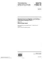
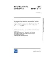
The flow chart in Figure 1 is an example showing such operations, where the specific stages
are expected to be defined, referencing the relevant internal documentation.
2.3
Technical abstract
2.3.1
TADD abstract (not for publication)
The Technology Approval technical abstract shall be declared by the technology approval
declaration document (TADD).
For each technology declared the following shall be identified:
•
Description of design tools used e.g. CAD systems, software;
•
Description of wafer fabrication processes including feature size, technology, types and
number of interconnects
–
e.g. 0,5 µm gate, GaAs MESFET, double layer metal;
LICENSED TO MECON Limited. - RANCHI/BANGALORE
FOR INTERNAL USE AT THIS LOCATION ONLY, SUPPLIED BY BOOK SUPPLY BUREAU.
Shipping includes the temporary storage of finished products before shipment to the
customer.
– 14 –
•
Description/list of products and/or family of products
–
•
e.g. low noise amplifiers; power amplifiers; switches;
Description of packaging types/materials and range of pincounts
ã
60747-16-10 â IEC:2004(E)
e.g. chip form: ceramic, DIL 8, 16 pin;
Description of test equipment, i.e. type of test equipment and scope.
An example of a Technology Approval technical abstract is given in 2.3.3.
2.3.2
QC 001005 abstract
LICENSED TO MECON Limited. - RANCHI/BANGALORE
FOR INTERNAL USE AT THIS LOCATION ONLY, SUPPLIED BY BOOK SUPPLY BUREAU.
The information to be published within QC 001005:2000, Register of Firms, Products and
Services approved under the IECQ-CECC System, including ISO 9000, may be based on the
information given to satisfy the Technology Approval technical abstract of 2.3.1. Information
marked with an asterisk (“*”) may be omitted in the published “Abstract of Technology
Approval” if requested by Control Site.
60747-16-10 © IEC:2004(E)
2.3.3
– 15 –
Example of a Technology Approval technical abstract
TECHNOLOGY DESCRIPTION: MONOLITHIC MICROWAVE INTEGRATED CICUIT
Manufacture [Control Site]:
IEC Reference:
Certificate Number:
TADD Generic:
Name and location
QC 210021 – TAS for Monolithic Microwave Integrated Circuits
Reference of the local SI
Control Site’s Document Reference
(Cross references to other TADD shall exist in the Generic Specification
where applicable).
WAFER FABRICATION:
Wafer Fabrication Process Name:
Wafer Fabrication Process Type:
Function:
Production Families:
Details:
Wafer Size:
Gate Length:
Maximum Interconnect Levels:*
Transmission line structure:
Metal Compositions:*
Gate Material:*
Passivation Material:*
Substrate Material:*
Number of masks:*
ASSEMBLY:
Package types:
Details:
Maximum Die Size:
Package materials:
Header/Leadframe:*
Pin/Lead Finish:
Die Attachment:*
Bond Wire Attachment:*
Package assembly
(e.g.
(e.g.
(e.g.
(e.g.
[ ] Others
“AMES0.5” etc.)
FET/Bipolar etc.)
Standard Cell/Custom etc.)
Low Noise/High Power/Control etc.)
(e.g. 100 mm)
(e.g. 0,5 µ m)
(Triple/Double/Single Level/Metal etc.)*
(e.g. microstrip/coplanar waveguide etc.)
(Al/Si/Al/Cu etc.)*
(Metal/Polysilicon etc.)*
(1,2 µ m Compressive Nitride etc.)*
(e.g. GaAs)*
(e.g. 8)*
(e.g. Thin Plastic Quad Flat Pack, 7,6 mm Small Outline (SO) etc.)
(e.g.
(e.g.
(e.g.
(e.g.
(e.g.
(e.g.
TPQFP – 9 x 9 mm: SO300 – 2,3 mm x 2,3 mm)
Ceramic/Epoxy/Plastic etc.)
Copper/Alloy 42 etc.)*
Gold/Solder Dipped etc.)
Silicon-Gold Eutectic etc.)*
Aluminium, Ultrasonic etc.)*
ELECTRICAL CHARACTERISTICS OF PRODUCTS:
Supply Voltage Range:
Maximum Input Power:
Total Power Dissipation:
Maximum Operating Frequency:
Operating Temperature Range:
Storage Temperature Range:
ENVIRONMENTAL/RELIABILITY LIMITS:
Endurance Test Performance:
(e.g. > x year at 55 °C or > 1 000 h at 125 °C)
Accelerated Damp Heat Severity:
(e.g. > x year at 55 °C/60 % RH or 1 000 h at 85 °C/85 % RH)
Temperature Cycling Extremes:
(e.g. –65 °C / +150 °C)
etc.
AND
Expected Failure Rate (under specified environments)
Quality Factor (π Q ).
(The limits of approval shall be made available to the customer, and any tests should correlate to IEC
test methods and should be suitable for the intended application.)
LICENSED TO MECON Limited. - RANCHI/BANGALORE
FOR INTERNAL USE AT THIS LOCATION ONLY, SUPPLIED BY BOOK SUPPLY BUREAU.
LIBRARY/DESIGN
Manufacturer’s name of the library:
Information on the library (where applicable):
Purpose:
[ ] Microwave Design [ ] Digital Design
Types:
[ ] Standard Cells
[ ] Element Cells
Contents:
Types of cells
– 16 –
2.4
60747-16-10 © IEC:2004(E)
Requirements for control of subcontractors
Where a technical process as defined in 2.1 is subcontracted, the procedures and criteria
employed to demonstrate control shall be specified. This may be achieved either by the
demonstration of conformance to the requirements of the appropriate PAS (Publicly Available
Specification) in the IECQ-CECC 200000 series, or by demonstrating that the processes have
been satisfactorily performed in accordance with criteria defined or referenced from the TADD.
Such criteria shall be capable of demonstrating compliance with the declaration of reliability
and environmental performance.
The following items shall be specified:
Reason for subcontracting
•
Name and address
•
IECQ-CECC Process and Approval or Technology Approval certificate reference (where
appropriate)
•
Name of CMB (Contract Management Branch) contract within the subcontractor
•
Documentation
•
Interrelationship documentation.
NOTE Design, mask manufacture, wafer fabrication, wafer probe, assembly, testing, packaging and shipping may
be subcontracted provided that the control site has the capability for at least one of the MAIN TECHNICAL
PROCESSES as defined in 6.2.1.3 of QC 001002-3.
LICENSED TO MECON Limited. - RANCHI/BANGALORE
FOR INTERNAL USE AT THIS LOCATION ONLY, SUPPLIED BY BOOK SUPPLY BUREAU.
•
60747-16-10 © IEC:2004(E)
– 17 –
CUSTOMER
Custom IC
INTEGRATED
CIRCUIT DESIGN
CENTRE
LICENSED TO MECON Limited. - RANCHI/BANGALORE
FOR INTERNAL USE AT THIS LOCATION ONLY, SUPPLIED BY BOOK SUPPLY BUREAU.
MASK
MANUFACTURE
WAFER
FABRICATION
PROBE
TEST
ASSEMBLY
TEST
PACKAGING
AND
SHIPPING
IEC
NOTE
876/04
This is an example of a packaged device.
Figure 1 – Example flow chart of design/manufacture/test
– 18 –
3
60747-16-10 © IEC:2004(E)
Component design of MMICs
3.1
Scope
Design information relevant to the technology for which approval is sought shall be included in
the TADD.
This shall include design of the semiconductor process incorporating modification and
publication of the process parameters and related process design rules in the form of written
and computer files suitable for use in CAD tools at either internal customers or independent
design centres.
The IC design centre is responsible for the design of integrated circuits in accordance with
customer requests as defined by product or other specifications, generally by translation from
received data into IC specifications, then design and simulation phases followed by
production of data, specifications, and computer files (or equivalent) required for manufacturing. This shall generally employ data from the process design task.
Activities may include mask making and writing product test programmes or test data suitable
for development into test programmes by a test centre or task.
3.2
Description of activities and flow charts
3.2.1
Description of activities
The activities of design for integrated circuits shall be declared, including flow charts showing
all activities, critical steps, check points and quality indicators, referencing the relevant
internal documentation. These shall include any or all of items a) to e) below, as appropriate:
a) Feasibility
The availability of equipment and of the design/manufacturing capacity to cover the
required production lot quantities shall be verified.
b) Process design
i)
Physical characteristics (required for circuit design)
ii)
Electrical characteristics
iii)
Layout rules.
c) Design services and support
i)
Design Rule Checker (DRC)
ii)
Layout Versus Schematic (LVS)
iii)
Process rules (wafer fab and assembly)
iv)
CAD Models.
d) Circuit design tools
i)
Linear simulation (frequency domain)
ii)
Harmonic balance
iii)
SPICE
iv)
Electromagnetic analysis
v)
Other.
LICENSED TO MECON Limited. - RANCHI/BANGALORE
FOR INTERNAL USE AT THIS LOCATION ONLY, SUPPLIED BY BOOK SUPPLY BUREAU.
Process characterization and circuit design are, in general, separate though inter-related
tasks, and so their interfaces with the process design task shall be specified in detail, including
management responsibilities, transfer specifications, requirements and deliverables.