Iec 60728 4 2007
Bạn đang xem bản rút gọn của tài liệu. Xem và tải ngay bản đầy đủ của tài liệu tại đây (1.15 MB, 36 trang )
IEC 60728-4
Edition 3.0
2007-08
INTERNATIONAL
STANDARD
IEC 60728-4:2007(E)
LICENSED TO MECON Limited. - RANCHI/BANGALORE
FOR INTERNAL USE AT THIS LOCATION ONLY, SUPPLIED BY BOOK SUPPLY BUREAU.
Cable networks for television signals, sound signals and interactive services –
Part 4: Passive wideband equipment for coaxial cable networks
THIS PUBLICATION IS COPYRIGHT PROTECTED
Copyright © 2007 IEC, Geneva, Switzerland
All rights reserved. Unless otherwise specified, no part of this publication may be reproduced or utilized in any form
or by any means, electronic or mechanical, including photocopying and microfilm, without permission in writing from
either IEC or IEC's member National Committee in the country of the requester.
If you have any questions about IEC copyright or have an enquiry about obtaining additional rights to this publication,
please contact the address below or your local IEC member National Committee for further information.
IEC Central Office
3, rue de Varembé
CH-1211 Geneva 20
Switzerland
Email:
Web: www.iec.ch
The International Electrotechnical Commission (IEC) is the leading global organization that prepares and publishes
International Standards for all electrical, electronic and related technologies.
About IEC publications
The technical content of IEC publications is kept under constant review by the IEC. Please make sure that you have the
latest edition, a corrigenda or an amendment might have been published.
Catalogue of IEC publications: www.iec.ch/searchpub
The IEC on-line Catalogue enables you to search by a variety of criteria (reference number, text, technical committee,…).
It also gives information on projects, withdrawn and replaced publications.
IEC Just Published: www.iec.ch/online_news/justpub
Stay up to date on all new IEC publications. Just Published details twice a month all new publications released. Available
on-line and also by email.
Electropedia: www.electropedia.org
The world's leading online dictionary of electronic and electrical terms containing more than 20 000 terms and definitions
in English and French, with equivalent terms in additional languages. Also known as the International Electrotechnical
Vocabulary online.
Customer Service Centre: www.iec.ch/webstore/custserv
If you wish to give us your feedback on this publication or need further assistance, please visit the Customer Service
Centre FAQ or contact us:
Email:
Tel.: +41 22 919 02 11
Fax: +41 22 919 03 00
LICENSED TO MECON Limited. - RANCHI/BANGALORE
FOR INTERNAL USE AT THIS LOCATION ONLY, SUPPLIED BY BOOK SUPPLY BUREAU.
About the IEC
IEC 60728-4
Edition 3.0
2007-08
INTERNATIONAL
STANDARD
INTERNATIONAL
ELECTROTECHNICAL
COMMISSION
ICS 33.060.40; 33.170
PRICE CODE
V
ISBN 2-8318-9265-1
LICENSED TO MECON Limited. - RANCHI/BANGALORE
FOR INTERNAL USE AT THIS LOCATION ONLY, SUPPLIED BY BOOK SUPPLY BUREAU.
Cable networks for television signals, sound signals and interactive services –
Part 4: Passive wideband equipment for coaxial cable networks
–2–
60728-4 © IEC:2007(E)
CONTENTS
FOREWORD...........................................................................................................................4
INTRODUCTION.....................................................................................................................6
Scope ...............................................................................................................................7
2
Normative references .......................................................................................................7
3
Terms, definitions, symbols and abbreviations.................................................................. 8
4
3.1 Terms and definitions ..............................................................................................8
3.2 Symbols ................................................................................................................ 12
3.3 Abbreviations ........................................................................................................ 13
Methods of measurement ............................................................................................... 13
4.1
5
Attenuation ............................................................................................................ 13
4.1.1 Test equipment.......................................................................................... 13
4.1.2 Measurement procedure ............................................................................ 13
4.1.3 Presentation of the results ......................................................................... 14
4.2 Isolation ................................................................................................................ 14
4.2.1 Definition ................................................................................................... 14
4.2.2 Test equipment.......................................................................................... 14
4.2.3 Measurement procedure ............................................................................ 14
4.2.4 Presentation of the results ......................................................................... 15
4.3 Through-loss ......................................................................................................... 15
4.3.1 Definition ................................................................................................... 15
4.3.2 Test equipment.......................................................................................... 15
4.3.3 Measurement procedure ............................................................................ 15
4.3.4 Presentation of the results ......................................................................... 15
4.4 Group delay variation ............................................................................................ 15
4.4.1 Definition ................................................................................................... 15
4.4.2 Test equipment.......................................................................................... 15
4.4.3 Method of measurement ............................................................................ 16
4.4.4 Presentation of the result........................................................................... 16
4.5 Amplitude frequency response .............................................................................. 16
4.6 Return loss ............................................................................................................ 16
4.7 Hum modulation of carrier ..................................................................................... 16
4.7.1 Definition ................................................................................................... 16
4.7.2 Description of the method of measurement ................................................ 17
4.7.3 Measuring procedure ................................................................................. 18
4.7.4 Calculating the hum-modulation ratio ......................................................... 19
4.7.5 Presentation of the results ......................................................................... 20
4.8 Two-carrier intermodulation measurements for second- and third-order
products ................................................................................................................ 20
Performance requirements and recommendations .......................................................... 21
5.1
General performance requirements and recommendations .................................... 21
5.1.1 Safety........................................................................................................ 21
5.1.2 Electromagnetic compatibility (EMC) ......................................................... 21
5.1.3 Environmental ........................................................................................... 21
5.1.4 Marking ..................................................................................................... 22
5.1.5 Impedance................................................................................................. 22
LICENSED TO MECON Limited. - RANCHI/BANGALORE
FOR INTERNAL USE AT THIS LOCATION ONLY, SUPPLIED BY BOOK SUPPLY BUREAU.
1
60728-4 © IEC:2007(E)
5.2
5.3
5.4
5.5
–3–
Bibliography
.................................................................................................................. 32
Annex A (informative) Measurement errors which occur due to mismatched equipment ....... 30
Annex B (informative) Differences in some countries ........................................................... 31
Figure 1 – Test set-up for the measurement of attenuation ................................................... 14
Figure 2 – Test set-up for the measurement of isolation ........................................................ 14
Figure 3 – Measurement of through-loss ............................................................................... 15
Figure 4 – Carrier/hum ratio .................................................................................................. 16
Figure 5 – Test set-up for power injectors ............................................................................. 17
Figure 6 – Test set-up for passive equipment, excluding power injectors .............................. 18
Figure 7 – Oscilloscope display ............................................................................................ 18
Figure 8 – Harmonic/Intermodulation test circuit ................................................................... 20
Figure 9 – Types of losses of system outlets......................................................................... 25
Figure A.1 – Error concerning return loss measurement........................................................ 30
Figure A.2 – Maximum ripple ................................................................................................ 30
Table 1 – Return loss of system outlets ................................................................................ 23
Table 2 – Return loss of looped-through system outlets ........................................................ 24
Table 3 – Maximum return path signal level derived from maximum allowed
intermodulation distortion level in the downstream frequency band ....................................... 26
Table 4 – Return loss of splitters and taps ............................................................................ 26
Table 5 – Isolation of splitters ............................................................................................... 27
Table 6 – Return loss for all other passive equipment ........................................................... 28
LICENSED TO MECON Limited. - RANCHI/BANGALORE
FOR INTERNAL USE AT THIS LOCATION ONLY, SUPPLIED BY BOOK SUPPLY BUREAU.
5.1.6 Degradation of performance caused by overvoltages ................................. 22
Performance requirements and recommendations for receiver lead ....................... 22
Performance requirements and recommendations for system outlets ..................... 22
5.3.1 Safety........................................................................................................ 22
5.3.2 Quality grading .......................................................................................... 22
5.3.3 Mechanical requirements ........................................................................... 23
5.3.4 Electrical parameters and requirements ..................................................... 23
Performance requirements and recommendations for splitters and taps ................ 26
5.4.1 Description ................................................................................................ 26
5.4.2 Mechanical requirements for connectors.................................................... 26
5.4.3 Electrical parameters and requirements ..................................................... 26
Performance requirements and recommendations for all other passive
equipment ............................................................................................................. 28
5.5.1 Description ................................................................................................ 28
5.5.2 Mechanical requirements for connectors.................................................... 28
5.5.3 Electrical parameters and requirements ..................................................... 28
–4–
60728-4 © IEC:2007(E)
INTERNATIONAL ELECTROTECHNICAL COMMISSION
____________
CABLE NETWORKS FOR TELEVISION SIGNALS,
SOUND SIGNALS AND INTERACTIVE SERVICES –
Part 4: Passive wideband equipment
for coaxial cable networks
FOREWORD
2) The formal decisions or agreements of IEC on technical matters express, as nearly as possible, an international
consensus of opinion on the relevant subjects since each technical committee has representation from all
interested IEC National Committees.
3) IEC Publications have the form of recommendations for international use and are accepted by IEC National
Committees in that sense. While all reasonable efforts are made to ensure that the technical content of IEC
Publications is accurate, IEC cannot be held responsible for the way in which they are used or for any
misinterpretation by any end user.
4) In order to promote international uniformity, IEC National Committees undertake to apply IEC Publications
transparently to the maximum extent possible in their national and regional publications. Any divergence
between any IEC Publication and the corresponding national or regional publication shall be clearly indicated in
the latter.
5) IEC provides no marking procedure to indicate its approval and cannot be rendered responsible for any
equipment declared to be in conformity with an IEC Publication.
6) All users should ensure that they have the latest edition of this publication.
7) No liability shall attach to IEC or its directors, employees, servants or agents including individual experts and
members of its technical committees and IEC National Committees for any personal injury, property damage or
other damage of any nature whatsoever, whether direct or indirect, or for costs (including legal fees) and
expenses arising out of the publication, use of, or reliance upon, this IEC Publication or any other IEC
Publications.
8) Attention is drawn to the Normative references cited in this publication. Use of the referenced publications is
indispensable for the correct application of this publication.
9) Attention is drawn to the possibility that some of the elements of this IEC Publication may be the subject of
patent rights. IEC shall not be held responsible for identifying any or all such patent rights.
International Standard IEC 60728-4 has been prepared by technical area 5: Cable networks
for television signals, sound signals and interactive services, of IEC technical committee 100:
Audio, video and multimedia systems and equipment.
This third edition cancels and replaces the second edition published in 2000, of which it
constitutes a technical revision.
This edition includes the following significant technical changes with respect to the previous
edition.
•
Subclause 3.1 includes several new or modified definitions.
•
Clause 4 includes added test methods for attenuation, isolation, through-loss, group delay
variation, amplitude frequency response and two carrier intermodulation measurements for
second- and third-order products.
•
Clause 5 includes updated and new performance requirements.
LICENSED TO MECON Limited. - RANCHI/BANGALORE
FOR INTERNAL USE AT THIS LOCATION ONLY, SUPPLIED BY BOOK SUPPLY BUREAU.
1) The International Electrotechnical Commission (IEC) is a worldwide organization for standardisation comprising
all national electrotechnical committees (IEC National Committees). The object of IEC is to promote
international co-operation on all questions concerning standardisation in the electrical and electronic fields. To
this end and in addition to other activities, IEC publishes International Standards, Technical Specifications,
Technical Reports, Publicly Available Specifications (PAS) and Guides (hereafter referred to as “IEC
Publication(s)”). Their preparation is entrusted to technical committees; any IEC National Committee interested
in the subject dealt with may participate in this preparatory work. International, governmental and nongovernmental organizations liaising with the IEC also participate in this preparation. IEC collaborates closely
with the International Organization for Standardisation (ISO) in accordance with conditions determined by
agreement between the two organizations.
60728-4 © IEC:2007(E)
–5–
The text of this standard is based on the following documents:
FDIS
Report on voting
100/1243/FDIS
100/1275/RVD
Full information on the voting for the approval of this standard can be found in the report on
voting indicated in the above table.
This publication has been drafted in accordance with the ISO/IEC Directives, Part 2.
For the differences existing in some countries, see Annex B.
The committee has decided that the contents of this publication will remain unchanged until
the maintenance result date indicated on the IEC web site under "" in
the data related to the specific publication. At this date, the publication will be
•
•
•
•
reconfirmed,
withdrawn,
replaced by a revised edition, or
amended.
A bilingual version of this publication may be issued at a later date.
LICENSED TO MECON Limited. - RANCHI/BANGALORE
FOR INTERNAL USE AT THIS LOCATION ONLY, SUPPLIED BY BOOK SUPPLY BUREAU.
The list of all parts of the IEC 60728 series, under the general title Cable networks for
television signals, sound signals and interactive services, can be found on the IEC website.
–6–
60728-4 © IEC:2007(E)
INTRODUCTION
Standards of the IEC 60728 series deal with cable networks including equipment and
associated methods of measurement for headend reception, processing and distribution of
television signals, sound signals and their associated data signals and for processing,
interfacing and transmitting all kinds of signals for interactive services using all applicable
transmission media.
This includes
•
CATV 1-networks;
•
MATV-networks and SMATV-networks;
•
individual receiving networks;
The extent of this standardization work is from the antennas and/or special signal source
inputs to the headend or other interface points to the network up to the terminal input.
The standardization of any user terminals (i.e., tuners, receivers, decoders, multimedia
terminals, etc.) as well as of any coaxial, balanced and optical cables and accessories thereof
is excluded.
—————————
1 This word encompasses the HFC networks used nowadays to provide telecommunications services, voice,
data, audio and video both broadcast and narrowcast.
LICENSED TO MECON Limited. - RANCHI/BANGALORE
FOR INTERNAL USE AT THIS LOCATION ONLY, SUPPLIED BY BOOK SUPPLY BUREAU.
and all kinds of equipment, systems and installations installed in such networks.
60728-4 © IEC:2007(E)
–7–
CABLE NETWORKS FOR TELEVISION SIGNALS,
SOUND SIGNALS AND INTERACTIVE SERVICES –
Part 4: Passive wideband equipment
for coaxial cable networks
1
Scope
This standard
•
covers the frequency range 5 MHz to 3 000 MHz;
•
identifies performance requirements for certain parameters;
•
lays down data publication requirements for certain parameters;
•
stipulates methods of measurements;
•
introduces minimum requirements defining quality grades.
There are three grades for all passive equipment except system outlets where there is only
one.
Different networks require the same performance and, when integrating networks, upgrading
will be avoided.
Practical experience has shown that these three grades meet most of the technical
requirements necessary for supplying a minimum signal quality to the subscribers. This
classification should not be considered as a requirement but as information for users and
manufacturers on the minimum quality criteria of the material required to install networks of
different sizes. The system operator should select appropriate material to meet the minimum
signal quality at the subscriber's outlet and to optimize cost/performance, taking into account
the size of the network and local circumstances.
All requirements and published data should be understood as guaranteed values within the
specified frequency range and in well-matched conditions.
2
Normative references
The following referenced documents are indispensable for the application of this document.
For dated references, only the edition cited applies. For undated references, the latest edition
of the referenced document (including any amendments) applies.
IEC 60068 (all parts), Environmental testing
IEC 60417, Graphical symbols for use on equipment
NOTE IEC 60417 can be consulted on the IEC website.
IEC 60529, Degrees of protection provided by enclosures (IP Code)
LICENSED TO MECON Limited. - RANCHI/BANGALORE
FOR INTERNAL USE AT THIS LOCATION ONLY, SUPPLIED BY BOOK SUPPLY BUREAU.
This part of IEC 60728 applies to system outlets, splitters and taps, passive single or multiple
port equipment comprising filters, attenuators, equalizers, galvanic isolators, power injectors,
cable splices, terminating resistors and transfer points, but excluding coaxial cables and
receiver leads (see 5.2).
–8–
60728-4 © IEC:2007(E)
IEC 60617, Graphical symbols for diagrams
IEC 60728 (all parts), Cable networks for television signals, sound signals and interactive
services
NOTE
The title of some of the parts of the IEC 60728 series will be changed when a new edition is published.
IEC 60966-1, Radio frequency and coaxial cable assemblies – Part 1: Generic specification –
General requirements and test methods
IEC 60966-2-4, Radio frequency and coaxial cable assemblies – Part 2-4: Detail specification
for cable assemblies for radio and TV receivers – Frequency range 0 to 3 000 MHz,
IEC 61169-2 connectors
IEC 60966-2-6, Radio frequency and coaxial cable assemblies – Part 2-6: Detail specification
for cable assemblies for radio and TV receivers – Frequency range 0 to 3 000 MHz,
IEC 61169-24 connectors
IEC 61000-4-5, Electromagnetic compatibility (EMC) – Part 4-5: Testing and measurement
techniques – Surge immunity test
IEC 61000-6-1, Electromagnetic compatibility (EMC) – Part 6-1: Generic standards –
Immunity for residential, commercial and light-industrial environments
IEC 61169-1, Radio-frequency connectors – Part 1: Generic specification – General requirements and measuring methods
IEC 61169-2, Radio-frequency connectors – Part 2: Sectional specification – Radio-frequency
coaxial connectors of type 9,52
IEC 61169-24, Radio-frequency connectors – Part 24: Sectional specification – Radiofrequency coaxial connectors with screw coupling, typically for use in 75 ohm cable
distribution systems (type F)
3
Terms, definitions, symbols and abbreviations
3.1
Terms and definitions
For the purposes of this document, the following terms and definitions apply.
NOTE
Some terms have been taken from IEC 60050-723.
3.1.1
active equipment
equipment (for example, amplifiers, converters, etc), performing signal processing by means
of external or internal power supply in a certain frequency range
3.1.2
amplitude frequency response
gain or loss of an equipment or system plotted against frequency
LICENSED TO MECON Limited. - RANCHI/BANGALORE
FOR INTERNAL USE AT THIS LOCATION ONLY, SUPPLIED BY BOOK SUPPLY BUREAU.
IEC 60966-2-5, Radio frequency and coaxial cable assemblies – Part 2-5: Detail specification
for cable assemblies for radio and TV receivers – Frequency range 0 to 1 000 MHz,
IEC 61169-2 connectors
60728-4 © IEC:2007(E)
–9–
3.1.3
attenuation
ratio of the input power to the output power of an equipment or system, usually expressed in
decibels
3.1.4
decibel ratio
ten times the logarithm of the ratio of two quantities of power, P 1 and P 2 , i.e.
P
10 lg 1 dB
P2
(1)
[IEV 723-09-25, modified]
3.1.6
directivity
attenuation between output port and interface or tap port, minus the attenuation between input
and interface or tap port, of any equipment or system
3.1.7
EM-active equipment
all passive and active equipment carrying RF signals are considered as EM-active equipment,
either because they are liable to cause electromagnetic disturbances or because the
performance of them is liable to be affected by such disturbances
3.1.8
equalizer
equipment designed to compensate over a certain frequency range for the
amplitude/frequency distortion or phase/frequency distortion introduced by feeders or
equipment
NOTE
This equipment is for the compensation of linear distortions only.
3.1.9
feeder
transmission path forming part of a cable network. Such a path may consist of a metallic
cable, optical fibre, wave guide or any combination of them. By extension, the term is also
applied to paths containing one or more radio links
[IEV 723-09-12, modified]
3.1.10
grade
classification of performance for equipment for use in cable networks. The choice of the
appropriate grade depends on, for example,
•
size of network;
•
structure of network;
•
lengths of cable between equipment;
•
kind of services;
LICENSED TO MECON Limited. - RANCHI/BANGALORE
FOR INTERNAL USE AT THIS LOCATION ONLY, SUPPLIED BY BOOK SUPPLY BUREAU.
3.1.5
directional coupler
tap
passive signal splitting equipment, with minimum signal loss between the input port and the
output port (through-loss), a specified coupling loss between the input port and the tap port
(tap loss), and very high loss between the output port and tap port (isolation)
10
ã
60728-4 â IEC:2007(E)
kind of signals
NOTE In any case, the system performance requirement should be fulfilled by the design of the network and the
choice of the grade of equipment used.
3.1.11
group delay variation
indicates the deviation from a linear phase-frequency response; the group delay is
τ=
dϕ
df
(2)
where
is the phase;
f
is the frequency.
Group delay variation (typically in ns) is the difference of the values of τ between the given
frequency and the reference frequency
3.1.12
isolation
attenuation between two output, tap or interface ports of any equipment or system
3.1.13
level
level of any power P 1 is the decibel ratio of that power to the standard reference power P 0 , i.e.
10 lg
P1
P0
(3)
level of any voltage U 1 is the decibel ratio of that voltage to the standard reference voltage
U 0 , i.e.
20 lg
U1
U0
(4)
NOTE This may be expressed in decibels (relative to 1 μV in 75 Ω) or more simply in dB(μV) if there is no risk of
ambiguity.
3.1.14
looped system outlet
device through which the spur feeder passes and to which is connected a receiver lead,
without the use of a subscriber’s feeder
[IEV 723-09-21]
3.1.15
nominal value
reference value around which a certain tolerance field (plus/minus) is permitted or specified
3.1.16
passive equipment
equipment (for example, splitters, tap-offs, system outlets, etc.) not requiring a power supply
in order to operate and/or not carrying out signal processing in a certain frequency range
LICENSED TO MECON Limited. - RANCHI/BANGALORE
FOR INTERNAL USE AT THIS LOCATION ONLY, SUPPLIED BY BOOK SUPPLY BUREAU.
ϕ
60728-4 © IEC:2007(E)
– 11 –
3.1.17
receiver lead
lead which connects the system outlet to the subscriber equipment
[IEV 723-09-23, modified]
NOTE 1 The meaning of receiver lead may not describe the function of this device if it is used for interactive
subscriber equipment; the definition already gives the more general explanation and allows bi-directional services.
NOTE 2
A receiver lead may include filters and balun transformers in addition to the cable.
3.1.18
r.f. data port
r.f. interface port to connect an interactive data equipment (for example, a modem) and
passes return band (upstream), as well as distribution (downstream) frequency band
[IEV 581-05-11]
3.1.20
splitter
equipment in which the signal power at the (input) port is divided equally or unequally
between two or more (output) ports
NOTE
This equipment may be used in the reverse direction for combining signal energy.
3.1.21
spur feeder
feeder to which splitters, subscriber taps or looped system outlets are connected
[IEV 723-09-16, modified]
3.1.22
standard reference power and voltage
in cable networks the standard reference power, P 0 , is 1/75 pW
NOTE
This is the power dissipated in a 75 Ω resistor with an r.m.s voltage drop of 1 μV across it.
The standard reference voltage, U 0 , is 1 μV.
3.1.23
subscriber feeder
feeder connecting a subscriber tap to a system outlet or, where the latter is not used, direct to
the subscriber equipment
[IEV 723-09-17, modified]
NOTE
A subscriber feeder may include filters and balun transformers.
3.1.24
subscriber tap
equipment with one or more ports for connecting a subscriber feeder to a spur feeder
3.1.25
system outlet
equipment for interconnecting a cable network and a receiver lead
LICENSED TO MECON Limited. - RANCHI/BANGALORE
FOR INTERNAL USE AT THIS LOCATION ONLY, SUPPLIED BY BOOK SUPPLY BUREAU.
3.1.19
splice
connecting device with barrel(s) accommodating electrical conductor(s) with or without
additional provision to accommodate and secure the insulation
60728-4 © IEC:2007(E)
– 12 –
3.1.26
transfer point
interface between the cable network and the internal network of the building, each of which
may be separately owned. The transfer point may contain a voltage-dependent device and/or
a galvanic isolator
3.1.27
well-matched
matching condition when the return loss of the equipment is sufficient that the expected error
can be neglected
NOTE Through mismatching of measurement instruments and the measurement object, measurement errors are
possible. Comments on the estimation of such errors are given in Annex A.
3.2
Symbols
NOTE
Numbers in brackets ([]) refer to symbols in IEC 60617 database.
Symbol
V
A
Terms
EUT
A
Terms
voltmeter
oscilloscope
[IEC 60617-S00059(2001:07)]
[IEC 60617-S00913(2001:07)]
[IEC 60617-S00059(2001:07)],
[IEC 60617-S00922(2001:07)]
ampere meter
[IEC 60617-S00059(2001:07)]
[IEC 60617-S00910(2001:07)]
variable generator
G
Symbol
[IEC 60617-S00081(2001:07)]
[IEC 60617-S01225(2001:07)]
[IEC 60617-S01403(2001:09)]
equipment under test
[IEC 60617-S00059(2001:07)]
P(f)
spectrum analyser
[IEC 60617-S00059(2001:07)]
[IEC 60617-S00910(2001:07)]
detector with LF-amplifier
[IEC 60617-S00118]
[IEC 60617-S01239]
adjustable a.c. voltage source
system outlet
low pass filter
looped through system outlet
high pass filter
variable attenuator
[IEC 60617-S01245(2001:07)]
[IEC 60617-S01248(2001:07)]
[IEC 60617-S01247(2001:07)]
r.f. choke
[IEC 60617-S00583(2001:07)]
ground
variable resistor
[IEC 60617-S00200(2001:07)]
[IEC 60617-S00557(2001:07)]
capacitor
[IEC 60617-S00567(2001:07)]
LICENSED TO MECON Limited. - RANCHI/BANGALORE
FOR INTERNAL USE AT THIS LOCATION ONLY, SUPPLIED BY BOOK SUPPLY BUREAU.
The following graphical symbols are used in the figures of this standard. These symbols are
either listed in IEC 60617 or based on symbols defined in IEC 60617.
60728-4 © IEC:2007(E)
3.3
– 13 –
Abbreviations
AC
alternating current
AM
amplitude modulation
CATV
community antenna television (system)
dBc means dB in relation to carrier level
DC
direct current
EM
electromagnetic
EMC
electromagnetic compatibility
EUT
equipment under test
FM
frequency modulation
HP
high pass
IP Class
international protection class
LF
low frequency
LP
low pass
MATV
master antenna television (system)
Q grade(s)
quality grade(s)
RF
radio frequency
RMS
root mean square
SMATV
satellite master antenna television (system)
TV
television
4
Methods of measurement
4.1
Attenuation
4.1.1
Test equipment
The following test equipment is required:
•
tuneable r.f. signal generator;
•
variable calibrated attenuator;
•
r.f. switch;
•
spectrum analyser or selective voltmeter.
NOTE
4.1.2
This test set is used as the basic method of measurement; normally, a network analyser is used.
Measurement procedure
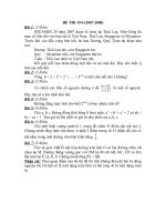
The equipment shall be connected as shown in Figure 1. Both r.f. switches shall be set to
position A. The variable attenuator shall be adjusted until a reference line on the spectrum
analyser or a reference value on the selective voltmeter is met. The value a 1 in dB of the
variable attenuator shall be read. Both r.f. switches shall be set to position B. The variable
attenuator shall be adjusted until the reference (line) is met again. The value a 2 in dB of the
variable attenuator shall be read.
LICENSED TO MECON Limited. - RANCHI/BANGALORE
FOR INTERNAL USE AT THIS LOCATION ONLY, SUPPLIED BY BOOK SUPPLY BUREAU.
dBc
60728-4 © IEC:2007(E)
– 14 –
A
f
G
A
P(f)
A
B
EUT
B
IEC 1475/07
Figure 1 – Test set-up for the measurement of attenuation
The attenuation in dB of the EUT for the chosen frequency is a 1 – a 2 . This procedure shall be
repeated at all relevant frequencies for the EUT.
4.1.3
Presentation of the results
4.2
Isolation
4.2.1
Definition
The isolation measured in dB is the attenuation ratio between two outputs of a component if
the signal is inserted in one of these outputs.
4.2.2
Test equipment
The following test equipment is required:
•
tuneable RF signal generator;
•
variable calibrated attenuator;
•
spectrum analyser or selective voltmeter;
•
RF switch.
NOTE
4.2.3
This test set is used as the basic method of measurement; normally, a network analyser is used
Measurement procedure
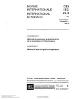
The equipment shall be connected as shown in Figure 2. Both RF switches shall be set to
position A. The variable attenuator shall be adjusted until a reference line on the spectrum
analyser or a reference value on the selective voltmeter is met. The value a 1 in dB of the
variable attenuator shall be read. Both RF switches shall be set to position B. The variable
attenuator shall be adjusted until the reference line is met again. The value a 2 in dB of the
variable attenuator shall be read. The signal shall be inserted into output port 2, the detector
connected to output port 1 and the procedure repeated.
A
f
G
A
B
Output 1
A
EUT
B
P(f)
Output 2
Input
IEC 1476/07
Figure 2 – Test set-up for the measurement of isolation
The isolation in dB of the EUT for the chosen frequency is a 1 − a 2 . This procedure shall be
repeated at all relevant frequencies for the EUT.
LICENSED TO MECON Limited. - RANCHI/BANGALORE
FOR INTERNAL USE AT THIS LOCATION ONLY, SUPPLIED BY BOOK SUPPLY BUREAU.
The attenuation of the EUT is expressed in dB, with reference to the chosen frequencies.
60728-4 © IEC:2007(E)
4.2.4
– 15 –
Presentation of the results
The isolation of the EUT is expressed in dB with reference to the chosen frequencies.
4.3
Through-loss
4.3.1
Definition
The through-loss, measured in dB, is the difference in signal level between the input and the
looped-through output of the equipment.
4.3.2
Test equipment
The following test equipment is required:
tuneable r.f. signal generator;
•
variable calibrated attenuator;
•
r.f. switch;
•
spectrum analyser or selective voltmeter.
NOTE
4.3.3
This test set is used as the basic method of measurement; normally, a network analyser is used
Measurement procedure
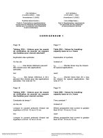
The equipment shall be connected as shown in Figure 3. Both r.f. switches shall be set to
position A. The variable attenuator shall be adjusted until a reference line on the spectrum
analyser or a reference value on the selective voltmeter is met. The value a 1 in dB of the
variable attenuator shall be read. Both r.f. switches shall be set to position B. The variable
attenuator shall be adjusted until the reference (line) is met again. The value a 2 in dB of the
variable attenuator shall be read.
A
f
G
A
A
B
P(f)
B
Input
EUT
Looped through output
Output
IEC 1477/07
Figure 3 – Measurement of through-loss
The insertion loss in dB of the EUT for the chosen frequency is a 1 – a 2.
4.3.4
Presentation of the results
The insertion loss of the EUT is expressed in dB, with reference to the chosen frequency.
4.4
4.4.1
Group delay variation
Definition
Group delay variation is defined as the deviation from a linear phase-frequency response.
4.4.2
Test equipment
A network analyser is required.
LICENSED TO MECON Limited. - RANCHI/BANGALORE
FOR INTERNAL USE AT THIS LOCATION ONLY, SUPPLIED BY BOOK SUPPLY BUREAU.
•
60728-4 © IEC:2007(E)
– 16 –
4.4.3
Method of measurement
For the measurement of group delay, a network analyser shall be used. To ensure a reliable
test result, the instructions of the test set manufacturer shall be met.
The phase shift is expressed as group delay by means of the formula:
τg =
Δϕ
360° ⋅ f m
(5)
where
Δ ϕ is the phase difference in degrees;
f m is the frequency of the test signal in Hertz;
The group delay variation is determined by using the formula above or is read directly on the
commercial measuring instrument.
4.4.4
Presentation of the result
The group delay variation is expressed in ns in the frequency range of the EUT.
4.5
Amplitude frequency response
For the measurement method of amplitude frequency response, see 4.1. The amplitude
response of an equipment or system is presented as a 1 − a 2 , plotted against frequency.
4.6
Return loss
Return-loss measurements shall be carried out as laid down in IEC 60728-3. Unused ports
shall be well-matched in 75 Ω or open/shorted if required.
4.7
4.7.1
Hum modulation of carrier
Definition
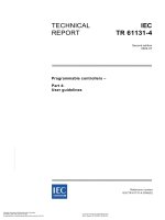
The interference ratio for hum modulation is the ratio stated in dB between the peak-to-peak
value of the unmodulated carrier and the peak-to-peak variation a of the envelope around the
carrier A caused by the hum modulating this carrier, i.e.
carrier/hum ratio = 20 lg
A
[dB]
a
Figure 4 illustrates the definition of the hum modulation of a carrier.
a
A
IEC 1478/07
Figure 4 – Carrier/hum ratio
LICENSED TO MECON Limited. - RANCHI/BANGALORE
FOR INTERNAL USE AT THIS LOCATION ONLY, SUPPLIED BY BOOK SUPPLY BUREAU.
τg is the group delay in seconds.
60728-4 © IEC:2007(E)
4.7.2
4.7.2.1
– 17 –
Description of the method of measurement
General
This measurement method is valid for radio and TV signal equipment within a cable network
that is supplied with 50 Hz a.c..
For measuring purposes, sinusoidal signals are used. Taking into account the maximum
admissible voltage or the maximum admissible current, the worst value for the operating
frequency range shall be published.
NOTE For cable networks, the peak value of the supply voltage or of the supply current can be higher than the
value resulting from calculation using the corresponding waveform factor.
For measurement an oscilloscope method is used.
Test equipment
The following test equipment is required:
•
adjustable voltage source;
•
variable load resistor;
•
power inserter;
•
variable calibrated attenuator;
•
oscilloscope;
•
voltmeter (r.m.s.);
•
ampere meter;
•
tuneable r.f. signal generator with sufficient phase-noise and hum-modulation ratio,
including AM capability (400 Hz);
•
detector including (battery-powered) low-frequency amplifier and 1 kHz LP filter in the
output, to suppress low-frequency distortion (an HP-filter at the input shall be used).
4.7.2.3
Connection of test equipment
The connection scheme for locally powered EUT is shown in Figure 5; the connection scheme
for remotely powered EUT is shown in Figure 6.
V
A
B
EUT
C
Power
inserter
A
A
f
G
Voltage
adjustment
R*
Current adjustment
1 kHz
* Necessary if the local powered
objects power other equipment
Figure 5 – Test set-up for power injectors
IEC 1479/07
LICENSED TO MECON Limited. - RANCHI/BANGALORE
FOR INTERNAL USE AT THIS LOCATION ONLY, SUPPLIED BY BOOK SUPPLY BUREAU.
4.7.2.2
60728-4 © IEC:2007(E)
– 18 –
Power
inserter
A
Power
inserter
B
EUT
1 kHz
A
f
G
A
Voltage
adjustment
V
R*
Current adjustment
objects power other equipment
IEC 1480/07
Figure 6 – Test set-up for passive equipment, excluding power injectors
4.7.3
4.7.3.1
Measuring procedure
Set-up of calibration
The reference signal is generated by means of the RF signal generator shown in Figure 5 and
Figure 6. An r.f. carrier frequency that suits the TV channel under consideration shall be
chosen and modulated to a depth of 1 % at a frequency of 400 Hz. The r.f. signal generator
shall be adjusted to an appropriate level and the peak-to-peak value of the demodulated AM
signal (c in Figure 7) read on the oscilloscope. This is the reference signal. With 1 %
modulation this value is:
–20 lg (0,01) = 40 dB
(6)
The modulation of the signal generator shall be switched off. The remaining value, m, in
Figure 7 is the value to be measured.
c
Calibration signal
m
Measured signal
IEC 1481/07
Figure 7 – Oscilloscope display
The suitability of the measuring set-up shall be checked by connecting points A and B
together and measuring the inherent hum of the set-up. The calculation of the hummodulation ratio is given in 4.7.4. This value should be at least 10 dB better than the values to
be measured on items of equipment. For measurements with set-up for locally powered EUT,
the set-up shown in Figure 5 shall be used for check. The subsequent measurements shall be
carried out in suitable increments through the entire operating frequency range. The
measured value is independent of the r.f. level; however, the r.f. level should be at least the
magnitude of the EUT operating level.
LICENSED TO MECON Limited. - RANCHI/BANGALORE
FOR INTERNAL USE AT THIS LOCATION ONLY, SUPPLIED BY BOOK SUPPLY BUREAU.
* Necessary if the locally powered
60728-4 © IEC:2007(E)
4.7.3.2
– 19 –
Locally powered EUT
The EUT shall be adjusted to maximum or minimum operating voltage using the transformer.
The supply current depends on the power requirement of the EUT.
The signal generator shall be modulated with the reference signal and the level at point B
shall be adjusted by means of an attenuator in such a way that neither the EUT is overdriven
nor the detector is within a non-admissible operating range. The peak-to-peak amplitude, c, of
the demodulated reference signal, which is displayed on the oscilloscope, shall be noted.
Then the reference signal shall be switched off and the peak-to-peak value, m, of the
remaining signal measured.
In addition, for EUT with remote supply terminals, the maximum admissible peak current for
the respective terminal shall be adjusted by means of resistor R.
Remotely supplied EUT
For remotely supplied EUT, the general procedure described in 4.7.3.2 shall be followed. The
only difference is that the supply energy is routed to the equipment via an r.f. terminal. In the
case where there are several r.f. interfaces available for power insertion, each of these
interfaces shall be included in the measurement procedure in a suitable manner.
4.7.4
4.7.4.1
Calculating the hum-modulation ratio
Frequency range
The frequency range considered for the hum is from 50 Hz to 1 kHz.
4.7.4.2
Individual EUT
The hum-modulation ratio [EUT] is equal to 40 dB + 20 lg (c/m) [dB] for 1 % reference
modulation depth.
For other chosen reference modulation depths, the value 40 dB shall be replaced by the result
of the term –20 lg (modulation depth).
4.7.4.3
Cascaded EUT
For high hum-modulation ratios, it can be useful to cascade several EUT for better
determination of the measuring values. Then, to calculate the individual EUT, the following
formula shall be used.
Hum-modulation ratio [EUT] = Hum-modulation ratio [cascaded] +20 lg n [dB]
where
n is the number of cascaded EUT.
4.7.4.4
Loop-value correction
If a set-up calibration correction is required, the following formula shall be used.
calibration correction ⎞
⎛ − measured value
−
⎟ [dB]
20
20
Hum-modulation ratio [EUT] = − 20lg ⎜10
− 10
⎟
⎜
⎠
⎝
(7)
LICENSED TO MECON Limited. - RANCHI/BANGALORE
FOR INTERNAL USE AT THIS LOCATION ONLY, SUPPLIED BY BOOK SUPPLY BUREAU.
4.7.3.3
– 20 –
4.7.5
60728-4 © IEC:2007(E)
Presentation of the results
The hum-modulation ratio is expressed in dB.
4.8
Two-carrier intermodulation measurements for second- and third-order products
Splitters, taps and directional couplers contain ferrite transformers. These transformers are
non-linear and produce harmonic and intermodulation products.
These are predominately third-order products and are insignificant (greater than 120 dBc),
providing the ferrite cores are not magnetised. If the cores become magnetized then
significant second-order products may be produced. Third harmonic products remain low.
It is not possible to stop equipment becoming magnetized in the CATV environment.
In order to carry out harmonic or intermodulation tests, it is therefore necessary to magnetize
equipment prior to test in order to simulate worst-case conditions. The surge immunity test
described in 5.1.6.2 provides adequate magnetization and may be used to precondition the
equipment under test.
As an alternative to the surge immunity test, a 25 V/500 μs pulse should be applied to each
port via a 300 Ω source impedance prior to testing.
In circuits each ferrite core appears as a coherent harmonic generator with a source
impedance determined by the relevant circuit elements. It is thus imperative that all of the
equipment ports are correctly terminated at all frequencies to enable correct measurements to
be taken.
For splitters and taps, the return path signal is applied to each output port OPx and
measurements are taken at either or both output ports via diplex filters (see Figure 8). The
harmonic signal present at the input port IP is of no significance.
75 Ω
Termination
IP
EUT
OP1
OP2
2f1 + 2f2
+ f1 + f2
f2
f1
75 Ω
Termination
IEC 1482/07
Figure 8 – Harmonic/Intermodulation test circuit
LICENSED TO MECON Limited. - RANCHI/BANGALORE
FOR INTERNAL USE AT THIS LOCATION ONLY, SUPPLIED BY BOOK SUPPLY BUREAU.
Ferrite transformers saturate easily when subjected to d.c. or pulse voltages. A typical splitter
input transformer will saturate in less than 10 V/μs. Following this saturation, the core will
remain magnetized.
60728-4 © IEC:2007(E)
– 21 –
Values for f 1 and f 2 are given in Table 3. Compensation should be made for the insertion loss
of the diplexers, which typically should have less than 1 dB loss at f 2 and 2· f 2 and a stop-band
loss greater than 80 dB. The crossover frequency should be approximately 2 ⋅ f1 ⋅ f 2 ) .
5
Performance requirements and recommendations
5.1
General performance requirements and recommendations
5.1.1
Safety
The relevant safety requirements as laid down in IEC 60728-11 shall be met.
5.1.2
Electromagnetic compatibility (EMC)
5.1.3
Environmental
Manufacturers shall publish relevant environmental information on their products in
accordance with the requirements of the following publications.
Storage
(simulated effects of)
IEC 60068-2-48
Transportation
Air freight (combined cold and low pressure)
IEC 60068-2-40
Road transport (bump test)
IEC 60068-2-29
Road transport (shock test)
IEC 60068-2-27
Installation or maintenance
Topple or drop test
IEC 60068-2-31
Free fall test
IEC 60068-2-32
Operation
IP Class. Protection provided by enclosures
IEC 60529
Climatic category of component or equipment for storage and
operation as defined in Annex A of
IEC 60068-1
Cold
IEC 60068-2-1
Dry heat
IEC 60068-2-2
Damp heat
IEC 60068-2-30
Change of temperature (Test Nb)
IEC 60068-2-14
Vibration (sinusoidal) Annex B of
IEC 60068-2-6
NOTE
For requirements in Finland, see Clause B.1.
This will enable users to judge the suitability of the product with regard to four main
requirements: storage, transportation, installation, and operation.
LICENSED TO MECON Limited. - RANCHI/BANGALORE
FOR INTERNAL USE AT THIS LOCATION ONLY, SUPPLIED BY BOOK SUPPLY BUREAU.
The relevant EMC requirements laid down in IEC 60728-2 shall be met. The EMC class A or B
shall be published. It is recommended that “Class A” or “Class B” be indicated on the product.
– 22 –
5.1.4
60728-4 © IEC:2007(E)
Marking
5.1.4.1
Marking of equipment
Each piece of equipment shall be legibly and durably marked with the manufacturer’s name
and type number.
5.1.4.2
Marking of ports
It is recommended that symbols in accordance with IEC 60417 should be used when marking
ports.
5.1.5
Impedance
The nominal impedance of all passive equipment shall be 75 Ω.
Degradation of performance caused by overvoltages
5.1.6.1
Introduction
Surges caused by overvoltages from switching and lightning transients may degrade the
performance of passive equipment.
For products with surge protection the manufacturer shall indicate “surge-proof” in the product
information and in the data sheet. For this equipment, the following requirements shall be
met.
5.1.6.2
Surge immunity
Passive equipment used at the subscriber premises and the spur feeder shall comply with
performance criterion B (according to IEC 61000-6-1) after a surge voltage of 1 kV according
to IEC 61000-4-5 (class 2, test level 2) has been applied. It shall be applied between the inner
and the outer conductor of each port.
5.1.6.3
Degradation of intermodulation performance
After the test according to 5.1.6.2, the intermodulation requirements as specified in 5.3.4.8
(system outlets) and 5.4.3.10 (splitters and taps) should still be met.
5.2
Performance requirements and recommendations for receiver lead
The performance requirements and recommendations for receiver leads are stated in
IEC 60966-1, IEC 60966-2-4, IEC 60966-2-5 and IEC 60966-2-6.
5.3
5.3.1
Performance requirements and recommendations for system outlets
Safety
Safety isolation can be incorporated in the system outlet and may be a requirement of local
regulations. The isolation shall meet the requirements of IEC 60728-11 for isolated system
outlets.
5.3.2
Quality grading
There is only one quality grade.
LICENSED TO MECON Limited. - RANCHI/BANGALORE
FOR INTERNAL USE AT THIS LOCATION ONLY, SUPPLIED BY BOOK SUPPLY BUREAU.
5.1.6
60728-4 © IEC:2007(E)
5.3.3
– 23 –
Mechanical requirements
5.3.3.1
Conduit box
The system outlet shall be compatible with the conduit box used, which may be nationally or
internationally standardized.
5.3.3.2
Interface ports
An IEC 61169-2 male connector shall be used for the TV interface port. An IEC 61169-2
female connector shall be used for the radio interface port.
These connectors shall conform to IEC 61169-1. As an alternative, female F-connectors in
accordance with IEC 61169-24 may be used.
Electrical parameters and requirements
5.3.4.1
Definitions
For outlets with integral filters, a relaxation of 3 dB in return loss and isolation requirements is
permissible in the pass-band edges. The pass-band edge is defined to be 8 MHz above the
lower and 8 MHz below the upper cut-off frequencies for AM-TV and, respectively, 30 MHz for
FM-TV, 4 MHz for FM-radio and 2 MHz for return path.
5.3.4.2
Return loss
The minimum return loss shall be according to Table 1 and Table 2.
Table 1 – Return loss of system outlets
Port
Input
Frequency range
5 MHz to 10 MHz
Shall be published
10 MHz to 47 MHz
≥14 dB
47 MHz to 950 MHz
950 MHz to 3 000 MHz
TV
47 MHz to 950 MHz
FM radio
87,5 MHz to 108 MHz
5 MHz to 10 MHz
RF data
Satellite
a
Requirement
≥(14 dB − 1,5 dB/octave) but ≥10 dB
≥10 dB in 87,5 to 108 MHz range
≥10 dB decreasing linearly to 6 dB
≥(14 dB − 1,5 dB/octave), but ≥10 dB a
≥10 dB
Shall be published
10 MHz to 47 MHz
≥14 dB
47 MHz to 950 MHz
≥(14 dB − 1,5 dB/octave) but ≥10 dB
950 MHz to 3 000MHz
≥10 dB decreasing linearly to 6 dB
950 MHz to 3 000 MHz
≥10 dB decreasing linearly to 6 dB
Recommended minimum value 10 dB up to 950 MHz.
NOTE
The specifications in Table 1 are not applicable for system outlets in Japan (see Clause B.3).
LICENSED TO MECON Limited. - RANCHI/BANGALORE
FOR INTERNAL USE AT THIS LOCATION ONLY, SUPPLIED BY BOOK SUPPLY BUREAU.
5.3.4