Iec 60728 10 2014
Bạn đang xem bản rút gọn của tài liệu. Xem và tải ngay bản đầy đủ của tài liệu tại đây (1.16 MB, 110 trang )
®
Edition 3.0 2014-03
INTERNATIONAL
STANDARD
NORME
INTERNATIONALE
Cable networks for television signals, sound signals and interactive services –
Part 10: System performance for return paths
IEC 60728-10:2014-03(en-fr)
Réseaux de distribution par câbles pour signaux de télévision, signaux de
radiodiffusion sonore et services interactifs –
Partie 10: Performances des systèmes de voie de retour
Copyrighted material licensed to BR Demo by Thomson Reuters (Scientific), Inc., subscriptions.techstreet.com, downloaded on Nov-27-2014 by James Madison. No further reproduction or distribution is permitted. Uncontrolled when printe
IEC 60728-10
All rights reserved. Unless otherwise specified, no part of this publication may be reproduced or utilized in any form
or by any means, electronic or mechanical, including photocopying and microfilm, without permission in writing from
either IEC or IEC's member National Committee in the country of the requester. If you have any questions about IEC
copyright or have an enquiry about obtaining additional rights to this publication, please contact the address below or
your local IEC member National Committee for further information.
Droits de reproduction réservés. Sauf indication contraire, aucune partie de cette publication ne peut être reproduite
ni utilisée sous quelque forme que ce soit et par aucun procédé, électronique ou mécanique, y compris la photocopie
et les microfilms, sans l'accord écrit de l'IEC ou du Comité national de l'IEC du pays du demandeur. Si vous avez des
questions sur le copyright de l'IEC ou si vous désirez obtenir des droits supplémentaires sur cette publication, utilisez
les coordonnées ci-après ou contactez le Comité national de l'IEC de votre pays de résidence.
IEC Central Office
3, rue de Varembé
CH-1211 Geneva 20
Switzerland
Tel.: +41 22 919 02 11
Fax: +41 22 919 03 00
www.iec.ch
About the IEC
The International Electrotechnical Commission (IEC) is the leading global organization that prepares and publishes
International Standards for all electrical, electronic and related technologies.
About IEC publications
The technical content of IEC publications is kept under constant review by the IEC. Please make sure that you have the
latest edition, a corrigenda or an amendment might have been published.
IEC Catalogue - webstore.iec.ch/catalogue
The stand-alone application for consulting the entire
bibliographical information on IEC International Standards,
Technical Specifications, Technical Reports and other
documents. Available for PC, Mac OS, Android Tablets and
iPad.
Electropedia - www.electropedia.org
The world's leading online dictionary of electronic and
electrical terms containing more than 30 000 terms and
definitions in English and French, with equivalent terms in 14
additional languages. Also known as the International
Electrotechnical Vocabulary (IEV) online.
IEC publications search - www.iec.ch/searchpub
The advanced search enables to find IEC publications by a
variety of criteria (reference number, text, technical
committee,…). It also gives information on projects, replaced
and withdrawn publications.
IEC Glossary - std.iec.ch/glossary
More than 55 000 electrotechnical terminology entries in
English and French extracted from the Terms and Definitions
clause of IEC publications issued since 2002. Some entries
have been collected from earlier publications of IEC TC 37,
77, 86 and CISPR.
IEC Just Published - webstore.iec.ch/justpublished
Stay up to date on all new IEC publications. Just Published
details all new publications released. Available online and
also once a month by email.
IEC Customer Service Centre - webstore.iec.ch/csc
If you wish to give us your feedback on this publication or
need further assistance, please contact the Customer Service
Centre:
A propos de l'IEC
La Commission Electrotechnique Internationale (IEC) est la première organisation mondiale qui élabore et publie des
Normes internationales pour tout ce qui a trait à l'électricité, à l'électronique et aux technologies apparentées.
A propos des publications IEC
Le contenu technique des publications IEC est constamment revu. Veuillez vous assurer que vous possédez l’édition la
plus récente, un corrigendum ou amendement peut avoir été publié.
Catalogue IEC - webstore.iec.ch/catalogue
Application autonome pour consulter tous les renseignements
bibliographiques
sur
les
Normes
internationales,
Spécifications techniques, Rapports techniques et autres
documents de l'IEC. Disponible pour PC, Mac OS, tablettes
Android et iPad.
Recherche de publications IEC - www.iec.ch/searchpub
La recherche avancée permet de trouver des publications IEC
en utilisant différents critères (numéro de référence, texte,
comité d’études,…). Elle donne aussi des informations sur les
projets et les publications remplacées ou retirées.
IEC Just Published - webstore.iec.ch/justpublished
Restez informé sur les nouvelles publications IEC. Just
Published détaille les nouvelles publications parues.
Disponible en ligne et aussi une fois par mois par email.
Electropedia - www.electropedia.org
Le premier dictionnaire en ligne de termes électroniques et
électriques. Il contient plus de 30 000 termes et définitions en
anglais et en franỗais, ainsi que les termes ộquivalents dans
14 langues additionnelles. Egalement appelé Vocabulaire
Electrotechnique International (IEV) en ligne.
Glossaire IEC - std.iec.ch/glossary
Plus de 55 000 entrộes terminologiques ộlectrotechniques, en
anglais et en franỗais, extraites des articles Termes et
Définitions des publications IEC parues depuis 2002. Plus
certaines entrées antérieures extraites des publications des
CE 37, 77, 86 et CISPR de l'IEC.
Service Clients - webstore.iec.ch/csc
Si vous désirez nous donner des commentaires sur cette
publication ou si vous avez des questions contactez-nous:
Copyrighted material licensed to BR Demo by Thomson Reuters (Scientific), Inc., subscriptions.techstreet.com, downloaded on Nov-27-2014 by James Madison. No further reproduction or distribution is permitted. Uncontrolled when printe
THIS PUBLICATION IS COPYRIGHT PROTECTED
Copyright © 2014 IEC, Geneva, Switzerland
®
Edition 3.0 2014-03
INTERNATIONAL
STANDARD
NORME
INTERNATIONALE
Cable networks for television signals, sound signals and interactive services –
Part 10: System performance for return paths
Réseaux de distribution par câbles pour signaux de télévision, signaux de
radiodiffusion sonore et services interactifs –
Partie 10: Performances des systèmes de voie de retour
INTERNATIONAL
ELECTROTECHNICAL
COMMISSION
COMMISSION
ELECTROTECHNIQUE
INTERNATIONALE
PRICE CODE
CODE PRIX
ICS 33.060.40
XA
ISBN 978-2-8322-1438-1
Warning! Make sure that you obtained this publication from an authorized distributor.
Attention! Veuillez vous assurer que vous avez obtenu cette publication via un distributeur agréé.
® Registered trademark of the International Electrotechnical Commission
Marque déposée de la Commission Electrotechnique Internationale
Copyrighted material licensed to BR Demo by Thomson Reuters (Scientific), Inc., subscriptions.techstreet.com, downloaded on Nov-27-2014 by James Madison. No further reproduction or distribution is permitted. Uncontrolled when printe
IEC 60728-10
IEC 60728-10:2014 © IEC 2014
CONTENTS
FOREWORD ........................................................................................................................... 6
INTRODUCTION ..................................................................................................................... 8
1
Scope .............................................................................................................................. 9
2
Normative references ...................................................................................................... 9
3
Terms, definitions, symbols and abbreviations ............................................................... 10
4
3.1
Terms and definitions ....................................................................................... 10
3.2
Symbols ........................................................................................................... 13
3.3
Abbreviations ................................................................................................... 14
Methods of measurement .............................................................................................. 14
4.1
4.2
4.3
4.4
4.5
4.6
4.7
General ............................................................................................................ 14
Set-up of the network ....................................................................................... 15
Measurement of channel level .......................................................................... 15
4.3.1
General .......................................................................................... 15
4.3.2
Equipment required ........................................................................ 15
4.3.3
Connection of the equipment .......................................................... 16
4.3.4
Measurement procedure for digitally modulated carriers ................. 16
4.3.5
Measurement procedure for intermittent digitally modulated
carriers ........................................................................................... 17
4.3.6
Presentation of the results .............................................................. 18
Measurement of amplitude response variation ................................................. 18
4.4.1
Background .................................................................................... 18
4.4.2
Equipment required ........................................................................ 18
4.4.3
Connection of the equipment .......................................................... 18
4.4.4
Calibration of equipment ................................................................. 18
4.4.5
Method of measurement ................................................................. 19
4.4.6
Presentation of the results .............................................................. 19
Measurement of signal to noise ratio (S D,RF /N) ................................................. 19
4.5.1
General .......................................................................................... 19
4.5.2
Equipment required ........................................................................ 19
4.5.3
Connection of the equipment .......................................................... 19
4.5.4
Measurement procedure ................................................................. 19
4.5.5
Presentation of the results .............................................................. 20
Measurement of multiple interference .............................................................. 20
4.6.1
General .......................................................................................... 20
4.6.2
Equipment required ........................................................................ 21
4.6.3
Connection of the equipment .......................................................... 21
4.6.4
Measurement procedure ................................................................. 21
4.6.5
Processing of the data .................................................................... 21
4.6.6
Presentation of the results .............................................................. 21
Measurement of impulse noise ......................................................................... 22
4.7.1
General .......................................................................................... 22
4.7.2
Equipment required ........................................................................ 22
4.7.3
Connection of the equipment .......................................................... 22
4.7.4
Measurement procedure ................................................................. 22
4.7.5
Processing of the data and presentation of the results .................... 23
Copyrighted material licensed to BR Demo by Thomson Reuters (Scientific), Inc., subscriptions.techstreet.com, downloaded on Nov-27-2014 by James Madison. No further reproduction or distribution is permitted. Uncontrolled when printe
–2–
–3–
4.8
5
Measurement of echo ratio ............................................................................... 23
4.8.1
General .......................................................................................... 23
4.8.2
Equipment required ........................................................................ 24
4.8.3
Connection of the equipment .......................................................... 25
4.8.4
Measurement procedure ................................................................. 25
4.8.5
Presentation of the results .............................................................. 25
Measurement of group delay variation.............................................................. 25
4.9
4.10
Measurement of frequency error ...................................................................... 26
4.10.1
General .......................................................................................... 26
4.10.2
Equipment required ........................................................................ 26
4.10.3
Connection of the equipment .......................................................... 26
4.10.4
Measurement procedure ................................................................. 26
4.10.5
Presentation of the result ................................................................ 27
Measurement of bit error ratio (BER) ............................................................... 27
4.11
4.11.1
General .......................................................................................... 27
4.11.2
Equipment required ........................................................................ 27
4.11.3
Connection of the equipment .......................................................... 28
4.11.4
Measurement procedure ................................................................. 28
4.11.5
Presentation of the results .............................................................. 28
Noise power ratio (NPR) measurement on return path ..................................... 28
4.12
4.12.1
General .......................................................................................... 28
4.12.2
Equipment required ........................................................................ 29
4.12.3
Connection of the equipment .......................................................... 29
4.12.4
Measurement procedure ................................................................. 30
4.12.5
Presentation of the results .............................................................. 31
4.12.6
Recommended correction factors .................................................... 31
4.12.7
Precautions during measurement .................................................... 32
4.12.8
NPR dynamic range ........................................................................ 32
10-Tone measurement ..................................................................................... 33
4.13
4.13.1
General .......................................................................................... 33
4.13.2
Measurement principle .................................................................... 34
4.13.3
Measurement procedure ................................................................. 34
Modulation error ratio (MER) measurement on return path ............................... 35
4.14
4.14.1
General .......................................................................................... 35
4.14.2
Equipment required ........................................................................ 36
4.14.3
Connection of the equipment .......................................................... 36
4.14.4
Measurement procedure ................................................................. 36
4.14.5
Presentation of the results .............................................................. 37
System performance requirements ................................................................................ 37
5.1
5.2
5.3
6
General ............................................................................................................ 37
Analogue parameters that influence the system performance ........................... 40
General requirements ...................................................................................... 42
5.3.1
Impedance ...................................................................................... 42
5.3.2
Maximum signal level ..................................................................... 42
Specific system performance requirements ...................................................... 42
5.4
System performance recommendations – Return path bandwidth .................................. 45
6.1
Frequency allocation ........................................................................................ 45
6.2
Transmission quality in the return path frequency ranges ................................. 45
Annex A (normative) Correction factors for noise ................................................................. 47
Copyrighted material licensed to BR Demo by Thomson Reuters (Scientific), Inc., subscriptions.techstreet.com, downloaded on Nov-27-2014 by James Madison. No further reproduction or distribution is permitted. Uncontrolled when printe
IEC 60728-10:2014 © IEC 2014
IEC 60728-10:2014 © IEC 2014
A.1
Signal level measurement ................................................................................ 47
A.2
Noise level measurement ................................................................................. 47
Annex B (normative) Correction factor for a spectrum analyser ............................................ 49
Annex C (normative) Null packet and PRBS definitions ........................................................ 50
C.1
Null packet definition ........................................................................................ 50
C.2
PRBS definition ................................................................................................ 51
Bibliography .......................................................................................................................... 52
Figure 1 – Reference points of an active return path system (example) ................................. 15
Figure 2 – Time domain representation of an upstream burst with marker on the
preamble of the DOCSIS signal ............................................................................................ 17
Figure 3 – Arrangement of test equipment for measurement of amplitude response
variation ................................................................................................................................ 18
Figure 4 − Echo rating graticule ............................................................................................ 24
Figure 5 – Arrangement of test equipment for measurement of echo ratio ............................. 25
Figure 6 – Test set-up for frequency stability measurement .................................................. 26
Figure 7 – Principle of BER measurement ............................................................................. 27
Figure 8 – Band-pass and band-stop filters response ............................................................ 29
Figure 9 – NPR test set up .................................................................................................... 30
Figure 10 – NPR versus RF power density applied at input of optical transmitter and
determination of OMI 100 % .................................................................................................. 31
Figure 11 – Example of the frequency response of the optional band-pass filter ................... 31
Figure 12 – Example of NPR dynamic range ......................................................................... 33
Figure 13 – Dynamic range plotted versus NPR .................................................................... 33
Figure 14 – Alternative NPR measurement principle ............................................................. 34
Figure 15 – Relationship between classical NPR method and multi-tone method .................. 35
Figure 16 – Test set-up for modulation error ratio (MER) measurement ................................ 36
Figure 17 – Example of constellation diagram for a 64QAM modulation format ..................... 37
Figure 18 – Return path signals affecting forward path signals .............................................. 38
Figure 19 – Forward path signals affecting return path signals .............................................. 39
Figure 20 – Return path signals of service 1 affecting return path signals of a different
service (e.g. service 2).......................................................................................................... 39
Figure 21 – Return path signals of a specific service (e.g. service 2) affecting return
path signals of the same service ........................................................................................... 39
Figure 22 – Identification of the most common sub-bands within the return path band
with limited transmission quality ............................................................................................ 46
Figure A.1 – Noise correction factor CF versus measured level difference D ......................... 48
Table 1 – Examples of the Nyquist bandwidth of digitally modulated carriers ........................ 16
Table 2 – Band-stop filter notch frequencies ......................................................................... 29
Table 3 – Summary of the requirements for MER according to ETSI EN 302 878-2,
V.1.1.1 (2011-11), (clause 6.2.22.3.2) ................................................................................... 41
Table 4 – System performance requirements for different modulation techniques for
BER = 10 –4 .......................................................................................................................... 43
Table 5 – Comparison of system performance parameters given in Table 4 with those
given in ETSI EN 302 878-2, V.1.1.1 (2011-11), specifications.............................................. 44
Copyrighted material licensed to BR Demo by Thomson Reuters (Scientific), Inc., subscriptions.techstreet.com, downloaded on Nov-27-2014 by James Madison. No further reproduction or distribution is permitted. Uncontrolled when printe
–4–
–5–
Table 6 – Return path frequency ranges ............................................................................... 45
Table 7 – Reasons for quality reduction in sub-bands of the return path ............................... 45
Table A.1 – Noise correction factor ....................................................................................... 47
Table C.1 – Null transport stream packet definition ............................................................... 51
Copyrighted material licensed to BR Demo by Thomson Reuters (Scientific), Inc., subscriptions.techstreet.com, downloaded on Nov-27-2014 by James Madison. No further reproduction or distribution is permitted. Uncontrolled when printe
IEC 60728-10:2014 © IEC 2014
IEC 60728-10:2014 © IEC 2014
INTERNATIONAL ELECTROTECHNICAL COMMISSION
____________
CABLE NETWORKS FOR TELEVISION SIGNALS,
SOUND SIGNALS AND INTERACTIVE SERVICES –
Part 10: System performance for return paths
FOREWORD
1) The International Electrotechnical Commission (IEC) is a worldwide organization for standardization comprising
all national electrotechnical committees (IEC National Committees). The object of IEC is to promote
international co-operation on all questions concerning standardization in the electrical and electronic fields. To
this end and in addition to other activities, IEC publishes International Standards, Technical Specifications,
Technical Reports, Publicly Available Specifications (PAS) and Guides (hereafter referred to as “IEC
Publication(s)”). Their preparation is entrusted to technical committees; any IEC National Committee interested
in the subject dealt with may participate in this preparatory work. International, governmental and nongovernmental organizations liaising with the IEC also participate in this preparation. IEC collaborates closely
with the International Organization for Standardization (ISO) in accordance with conditions determined by
agreement between the two organizations.
2) The formal decisions or agreements of IEC on technical matters express, as nearly as possible, an international
consensus of opinion on the relevant subjects since each technical committee has representation from all
interested IEC National Committees.
3) IEC Publications have the form of recommendations for international use and are accepted by IEC National
Committees in that sense. While all reasonable efforts are made to ensure that the technical content of IEC
Publications is accurate, IEC cannot be held responsible for the way in which they are used or for any
misinterpretation by any end user.
4) In order to promote international uniformity, IEC National Committees undertake to apply IEC Publications
transparently to the maximum extent possible in their national and regional publications. Any divergence
between any IEC Publication and the corresponding national or regional publication shall be clearly indicated in
the latter.
5) IEC itself does not provide any attestation of conformity. Independent certification bodies provide conformity
assessment services and, in some areas, access to IEC marks of conformity. IEC is not responsible for any
services carried out by independent certification bodies.
6) All users should ensure that they have the latest edition of this publication.
7) No liability shall attach to IEC or its directors, employees, servants or agents including individual experts and
members of its technical committees and IEC National Committees for any personal injury, property damage or
other damage of any nature whatsoever, whether direct or indirect, or for costs (including legal fees) and
expenses arising out of the publication, use of, or reliance upon, this IEC Publication or any other IEC
Publications.
8) Attention is drawn to the Normative references cited in this publication. Use of the referenced publications is
indispensable for the correct application of this publication.
9) Attention is drawn to the possibility that some of the elements of this IEC Publication may be the subject of
patent rights. IEC shall not be held responsible for identifying any or all such patent rights.
International Standard IEC 60728-10 has been prepared by technical area 5: Cable networks
for television signals, sound signals and interactive services of IEC technical committee 100:
Audio, video and multimedia systems and equipment.
This third edition cancels and replaces the second edition published in 2005 and constitutes a
technical revision.
This edition includes the following significant technical changes with respect to the previous
edition:
•
update on the state-of-the-art of return path transmission in cable networks;
•
provisions for DOCSIS 3.0 and EuroDOCSIS 3.0 transmission standards;
•
revision of subclause 4.3 on measurement of channel level;
•
new subclause 4.12 for method of measurement of noise power ratio (NPR) on return
paths;
Copyrighted material licensed to BR Demo by Thomson Reuters (Scientific), Inc., subscriptions.techstreet.com, downloaded on Nov-27-2014 by James Madison. No further reproduction or distribution is permitted. Uncontrolled when printe
–6–
–7–
•
new subclause 4.13 for 10-tone measurements;
•
new subclause 4.14 for method of measurement of modulation error ratio (MER);
•
revision of subclause 5.2 on analogue parameters influencing system performance.
The text of this standard is based on the following documents:
FDIS
Report on voting
100/2247/FDIS
100/2283/RVD
Full information on the voting for the approval of this standard can be found in the report on
voting indicated in the above table.
This publication has been drafted in accordance with the ISO/IEC Directives, Part 2.
The list of all the parts of the IEC 60728 series under the general title Cable networks for
television signals, sound signals and interactive services, can be found on the IEC website.
The committee has decided that the contents of this publication will remain unchanged until
the stability date indicated on the IEC web site under "" in the data
related to the specific publication. At this date, the publication will be
•
reconfirmed,
•
withdrawn,
•
replaced by a revised edition, or
•
amended.
Copyrighted material licensed to BR Demo by Thomson Reuters (Scientific), Inc., subscriptions.techstreet.com, downloaded on Nov-27-2014 by James Madison. No further reproduction or distribution is permitted. Uncontrolled when printe
IEC 60728-10:2014 © IEC 2014
IEC 60728-10:2014 © IEC 2014
INTRODUCTION
Standards and deliverables of IEC 60728 series deal with cable networks including equipment
and associated methods of measurement for headend reception, processing and distribution
of television and sound signals and for processing, interfacing and transmitting all kinds of
data signals for interactive services using all applicable transmission media. These signals
are typically transmitted in networks by frequency-multiplexing techniques.
This includes for instance
•
regional and local broadband cable networks,
•
extended satellite and terrestrial television distribution systems,
•
individual satellite and terrestrial television receiving systems,
and all kinds of equipment, systems and installations used in such cable networks, distribution
and receiving systems.
The extent of this standardization work is from the antennas and/or special signal source
inputs to the headend or other interface points to the network up to the terminal input of the
customer premises equipment.
The standardization work will consider coexistence with users of the RF spectrum in wired
and wireless transmission systems.
The standardization of any user terminals (i.e. tuners, receivers, decoders, multimedia
terminals etc.) as well as of any coaxial, balanced and optical cables and accessories thereof
is excluded.
Specific equipment installed in cable networks for the operation of such return paths is
standardised in the relevant equipment standards. See IEC 60728-3, IEC 60728-4,
IEC 60728-5, IEC 60728-6.
Copyrighted material licensed to BR Demo by Thomson Reuters (Scientific), Inc., subscriptions.techstreet.com, downloaded on Nov-27-2014 by James Madison. No further reproduction or distribution is permitted. Uncontrolled when printe
–8–
–9–
CABLE NETWORKS FOR TELEVISION SIGNALS,
SOUND SIGNALS AND INTERACTIVE SERVICES –
Part 10: System performance for return paths
1
Scope
This part of IEC 60728 specifies the transparent return path of cable networks operated in the
frequency range between 5 MHz and 85 MHz or parts thereof. The upper frequency limit of
the return path is reduced to 65 MHz where FM radio signals are transmitted in a cable
network. Higher frequencies may be used in fibre based networks.
NOTE In addition, it is possible to use the frequency range from 0 MHz to 5 MHz for return path transmissions, for
example for NMS or other control, monitoring and signalling purposes. Applications below 5 MHz are not covered
by this standard.
Specifications of transmission systems (e.g. DOCSIS) are not within the scope of this
standard.
2
Normative references
The following documents, in whole or in part, are normatively referenced in this document and
are indispensable for its application. For dated references, only the edition cited applies. For
undated references, the latest edition of the referenced document (including any
amendments) applies.
IEC 60728 (all parts), Cable networks for television signals, sound signals and interactive
services
IEC 60728-1, Cable networks for television signals, sound signals and interactive services –
Part 1: System performance of forward paths
IEC 60728-2, Cable networks for television signals, sound signals and interactive services –
Part 2: Electromagnetic compatibility for equipment
IEC 60728-5, Cable networks for television signals, sound signals and interactive services –
Part 5: Headend equipment
IEC 60728-12, Cabled distribution systems for television and sound signals – Part 12:
Electromagnetic compatibility of systems
ISO/IEC 13818-1:2007, Information technology − Generic coding of moving pictures and
associated audio information − Part 1: Systems
ITU-R BT.470, Conventional analogue television systems
CLC/TR 50083-10-1:2009, Guidelines for the implementation of return paths in cable networks
ETSI ES 200 800, Digital Video Broadcasting (DVB); DVB interaction channel for Cable TV
distribution systems (CATV)
Copyrighted material licensed to BR Demo by Thomson Reuters (Scientific), Inc., subscriptions.techstreet.com, downloaded on Nov-27-2014 by James Madison. No further reproduction or distribution is permitted. Uncontrolled when printe
IEC 60728-10:2014 © IEC 2014
IEC 60728-10:2014 © IEC 2014
ETSI EN 302 878-2, V.1.1.1 (2011-11), Access, Terminals, Transmission and Multiplexing
(ATTM); Third Generation Transmission Systems for Interactive Cable Television Services –
IP Cable Modems; Part 2: Physical Layer; DOCSIS 3.0
3
3.1
Terms, definitions, symbols and abbreviations
Terms and definitions
For the purposes of this document, the following terms and definitions apply.
3.1.1
amplitude response variation
peak-to-peak variation in frequency amplitude response of a specified signal path over a
specified frequency band
Note 1 to entry:
The amplitude response variation is expressed in dB.
3.1.2
broadcast signal
signal comprising video and/or audio and/or data content distributed to several receivers
simultaneously
3.1.3
CATV network
regional and local broadband cable networks designed to provide sound and television signals
as well as signals for interactive services to a regional or local area
Note 1 to entry:
Originally defined as Community Antenna Television network.
3.1.4
channel availability
percentage of the time during which the channel fulfils all performance requirements
Note 1 to entry:
The duration of the observation time shall be published.
3.1.5
extended satellite television distribution network or system
distribution network or system designed to provide sound and television signals received by
satellite receiving antennas to households in one or more buildings
Note 1 to entry: This kind of network or system can possibly be combined with terrestrial antennas for the
additional reception of TV and/or radio signals via terrestrial networks.
Note 2 to entry: This kind of network or system can also carry control signals for satellite switched systems or
other signals for special transmission systems (e.g. MoCA or WiFi) in the return path direction.
3.1.6
extended terrestrial television distribution network or system
distribution network or system designed to provide sound and television signals received by
terrestrial receiving antennas to households in one or more buildings
Note 1 to entry: This kind of network or system can possibly be combined with a satellite antenna for the
additional reception of TV and/or radio signals via satellite networks.
Note 2 to entry: This kind of network or system can also carry other signals for special transmission systems (e.g.
MoCA or WiFi) in the return path direction.
3.1.7
forward path direction
direction of signal flow in a cable network from the headend or any other central point (node)
of a cable network to the subscribers' area
Copyrighted material licensed to BR Demo by Thomson Reuters (Scientific), Inc., subscriptions.techstreet.com, downloaded on Nov-27-2014 by James Madison. No further reproduction or distribution is permitted. Uncontrolled when printe
– 10 –
– 11 –
3.1.8
forward path
part of a cable network by which signals are distributed in the forward path direction from the
headend or any other central point (node) of a cable network to the subscribers' area
Note 1 to entry:
The forward path was formerly referred to as downstream.
3.1.9
frequency error
quality of supply evaluated on the basis of the actual frequency of an electrical system
compared to its nominal value
Note 1 to entry:
Frequency error consists of initial error, and short term and long term frequency stability.
3.1.10
headend
equipment connected between receiving antennas or other signal sources and the remainder
of the cable network, to process the signals to be distributed
Note 1 to entry: The headend may, for example, comprise antenna amplifiers, frequency converters, combiners,
separators and generators.
3.1.11
hybrid fibre coaxial network
HFC
cable network which is comprised of optical equipment and cables and coaxial equipment and
cables in different parts
3.1.12
impulse noise
noise caused by electromagnetic interference into cable networks
Note 1 to entry:
Impulse noise is characterised by pulses with a duration of typically <10 µs.
3.1.13
individual satellite television receiving system
system designed to provide sound and television signals received from satellite(s) to an
individual household
Note 1 to entry: This kind of system can also carry control signals for satellite switched systems or other signals
for special transmission systems (e.g. MoCA or WiFi) in the return path direction.
3.1.14
individual terrestrial television receiving system
system designed to provide sound and television signals received via terrestrial broadcast
networks to an individual household
Note 1 to entry: This kind of system could also carry other signals for special transmission systems (e.g. MoCA or
WiFi) in the return path direction.
3.1.15
ingress noise
noise caused by electromagnetic interference into cable networks
Note 1 to entry: The power of the ingress noise decreases with increasing frequency. It is permanently present
but it varies slowly in its intensity as a function of time.
3.1.16
interaction path
part of a cable network by which interactive signals are transmitted in the forward path
direction (from the headend or node to the subscriber) and in the return path direction (from
the subscriber to the headend or node)
Copyrighted material licensed to BR Demo by Thomson Reuters (Scientific), Inc., subscriptions.techstreet.com, downloaded on Nov-27-2014 by James Madison. No further reproduction or distribution is permitted. Uncontrolled when printe
IEC 60728-10:2014 © IEC 2014
IEC 60728-10:2014 © IEC 2014
3.1.17
local broadband cable network
network designed to provide sound and television signals as well as signals for interactive
services to a local area (e.g. one town or one village)
3.1.18
location specific noise
noise which occurs at a specific area of a cable network or which occurs in a cable network
located in a specific environment
3.1.19
MATV network
extended terrestrial television distribution networks or systems designed to provide sound and
television signals received by terrestrial receiving antennas to households in one or more
buildings
Note 1 to entry:
Originally defined as master antenna television network.
Note 2 to entry: This kind of network or system can possibly be combined with a satellite antenna for the
additional reception of TV and/or radio signals via satellite networks.
Note 3 to entry: This kind of network or system can also carry other signals for special transmission systems (e.g.
MoCA or WiFi) in the return path direction.
3.1.20
multiple interference
interfering signal which consists of at least two signals that originated from at least two
different sources
Note 1 to entry:
products.
On return path the multiple interference consists of ingress noise and intermodulation distortion
3.1.21
multimedia signal
signal comprising two or more different media contents, for example, video, audio, text, data,
etc.
3.1.22
network management system
NMS
software based system for controlling and supervising cable networks
3.1.23
network segment
part of a cable network comprising a set of functions and/or a specific extent of the complete
cable network
3.1.24
network termination
electrical termination of a cable network at any outlet on subscribers' side and headend or
node side
3.1.25
node
central point of a network segment at which signals can be fed into the forward path or can be
gathered from a number of subscribers out of the return path
3.1.26
regional broadband cable network
network designed to provide sound and television signals as well as signals for interactive
services to a regional area covering several towns and/or villages
Copyrighted material licensed to BR Demo by Thomson Reuters (Scientific), Inc., subscriptions.techstreet.com, downloaded on Nov-27-2014 by James Madison. No further reproduction or distribution is permitted. Uncontrolled when printe
– 12 –
– 13 –
3.1.27
return path
part of a cable network by which signals are transmitted in the return path direction from any
subscriber, connected to the network, to the headend or any other central point (node) of a
cable network
Note 1 to entry:
The return path was referred to as upstream before.
3.1.28
return path direction
direction of signal flow in a cable network from a subscriber to the headend or any other
central point (node) of a cable network
3.1.29
SMATV network
extended distribution networks or systems designed to provide sound and television signals
received by satellite receiving antennas to households in one or more buildings
Note 1 to entry:
Originally defined as satellite master antenna television network.
Note 2 to entry: This kind of network or system can possibly be combined with terrestrial antennas for the
additional reception of TV and/or radio signals via terrestrial networks.
Note 3 to entry: This kind of network or system can also carry control signals for satellite switched systems or
other signals for special transmission systems (e.g. MoCA or WiFi) in the return path direction.
3.2
Symbols
The following graphical symbols are used in the figures of this standard. These symbols are
either listed in IEC 60617, IEC 60417 or based on symbols defined in IEC 60617.
Symbols
O
E
G
Terms
Optical receiver
[IEC 60617-S00213 (2001-07)]
Symbols
P(f)
Terms
Electrical spectrum analyzer
[IEC 60617-S00910
(2001-07)]
Test waveform generator
[IEC 60617-S01225 (2001-07)]
Passive distribution network
[IEC 60617-S00910
(2001-07)]
G
Variable signal generator
[IEC 60617-S00899 (2001-07),
IEC 60617-S01403 (2001-09),
IEC 60617-S00081 (2001-07)]
Oscilloscope
[IEC 60617-S00059,
IEC 60617-S00922 (2001-07)]
A
Variable attenuator
[IEC 60617-S01245 (2001-07)]
Low pass filter
[IEC 60617-S01248
(2001-07)]
High pass filter
[IEC 60617-S01247 (2001-07)]
SUT/NUT
System under test/
Network under test
[IEC 60617-S00060
(2007-07)]
Demodulator
[IEC 60417-5260 (2002-10)]
Modulator
[IEC 60417-5261
(2002-10)]
Amplifier with return path amplifier
[IEC 60617-S00433 (2001-07)]
Bit error rate detector
[IEC 60617-S00059,
IEC 60617-S00910
(2001-07)]
BER
Copyrighted material licensed to BR Demo by Thomson Reuters (Scientific), Inc., subscriptions.techstreet.com, downloaded on Nov-27-2014 by James Madison. No further reproduction or distribution is permitted. Uncontrolled when printe
IEC 60728-10:2014 © IEC 2014
3.3
IEC 60728-10:2014 © IEC 2014
Abbreviations
The following abbreviations are used in this standard:
BER
bit error ratio
BW
bandwidth, equivalent noise
bandwidth
CATV
community antenna television
CB
citizen band
CIN
composite intermodulation noise
CM
cable modem
C/MI
carrier-to-multiple interference
ratio
CMTS
cable modem termination system
C/N
carrier-to-noise ratio
DVB
digital video broadcasting
EMC
electromagnetic compatibility
FM
frequency modulation
FSK
frequency shift keying
HFC
hybrid fibre coaxial
HNI
home network interface
IF
intermediate frequency
ISM
industrial, scientific, medical
LPF
low-pass filter
MATV
master antenna television
(network)
MER
modulation error ratio
MoCA
multimedia over cable alliance
NMS
network management system
NPR
noise power ratio
NUT
network under test
OFDM
orthogonal frequency division
multiplexing
OMI
optical modulation index
PRBS
pseudo random binary sequence
QAM
quadrature amplitude modulation
QPSK
quaternary phase shift keying
RF
radio frequency
RMS
root mean square
RBW
resolution bandwidth
S
signal level, before corrections
SCDMA
synchronous code division
multiple access
SL
signal level (corrected)
SMATV
satellite master antenna television
(network)
S/N
signal-to-noise ratio
S D,RF /N
signal-to-noise ratio
(RF digital signal)
SUT
system under test
TDMA
time division multiple access
TV
television
WiFi
wireless fidelity
4
4.1
Methods of measurement
General
An active return path carries typically only return signals. A passive return path can be used
for both return and forward signals.
This standard lays down the basic methods of measurement for signals typically used in the
return path of cable networks in order to assess the performance of those signals and their
performance limits.
All requirements refer to the performance limits, which shall be obtained between the
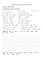
reference points (Figure 1) of the return path system.
One reference point is the network termination unit (NTU) close to the home network interface
HNI or to the subscriber system outlet (SO). It is the last point where all forward and return
signals are present and carried on the same cable. If no network termination unit exists, the
reference point is the HNI or the system outlet.
Copyrighted material licensed to BR Demo by Thomson Reuters (Scientific), Inc., subscriptions.techstreet.com, downloaded on Nov-27-2014 by James Madison. No further reproduction or distribution is permitted. Uncontrolled when printe
– 14 –
– 15 –
The other reference point is the input of the return signal receiver (or transceiver) in the
CMTS. At this point, the transparent signal path ends and beyond this point, the signal is
treated in a non-transparent way. The return signal receiver can be situated at the headend
but can also be at the node of the coaxial cell or at any other point of the network (where the
CMTS is located).
Optical node
Headend/Hub
E
E
CMTS
O
O
O
O
O
O
NTU
E
Wireless
Video
Voice
Data
E
O
HNI
Reference point
IEC 0737/14
Figure 1 – Reference points of an active return path system (example)
In addition to the system performance requirements for the transparent return path, system
performance recommendations were laid down in this standard. This includes, for example,
the overall frequency allocation, the use of specific modulation techniques for different
interactive multimedia services or different sub-bands within the return path frequency range,
etc.
4.2
Set-up of the network
Although the main target of this clause is to describe the measurement methods for the
performance of the return path, it is very important to do this on a properly aligned network
plant. Clause 8 “Installation and maintenance” of CLC/TR 50083-10-1:2009 is referenced
where the signal level adjustment is described in detail for the forward path and the return
path directions.
4.3
4.3.1
Measurement of channel level
General
The method described is applicable to the measurement of the channel level of digitally
modulated carriers and the channel level of intermittent digitally modulated carriers. The
channel level of a digitally modulated carrier is the RMS voltage of a sinusoidal signal that
would produce the same heating in a 75 Ω resistor as does the actual signal. For an
intermittent digitally modulated channel, that occupies one assigned time slot in a time
division multiple access (TDMA) sequence of time slots, the level to be considered shall be
the equivalent level as if the signal being measured (any one of the multiple signals included
in the total sequence) was transmitted continuously.
NOTE The terms “Signal level, carrier level, channel level, carrier power and channel power” are often used as
synonyms. For a continuous wave signal the term “carrier level” is the most appropriate. When the carrier is
modulated with digital information, the most suitable terms are “channel level” or “channel power”. Systems in the
return path are loaded with modulated carriers, which in most cases are digitally modulated carriers.
4.3.2
Equipment required
The equipment required is a spectrum analyzer having a known noise bandwidth and a
calibrated display. The calibration accuracy should be preferably within 0,5 dB.
Copyrighted material licensed to BR Demo by Thomson Reuters (Scientific), Inc., subscriptions.techstreet.com, downloaded on Nov-27-2014 by James Madison. No further reproduction or distribution is permitted. Uncontrolled when printe
IEC 60728-10:2014 © IEC 2014
4.3.3
IEC 60728-10:2014 © IEC 2014
Connection of the equipment
Connect the measuring equipment to the point where the measurement shall be performed by
using a suitable connection lead. Take care to ensure correct impedance matching.
4.3.4
Measurement procedure for digitally modulated carriers
The measurement procedure comprises the following steps:
a) if a high level ambient field is present, check that the measuring equipment has no
spurious readings. Connect a shielded termination to the connection lead, place the test
equipment and the connection lead approximately in their measuring positions and check
that there is a negligible reading at the frequency/frequencies and on the meter ranges to
be used;
b) tune the spectrum analyzer to the channel that shall be measured (by selecting the centre
frequency of the spectrum analyzer) and select the span and level settings to show the
whole channel. Examples of the Nyquist bandwidth of digitally modulated carriers are
given in Table 1;
Table 1 – Examples of the Nyquist bandwidth of digitally modulated carriers
Type of digital channel
Mbit/s
Nyquist bandwidth
MHz
QPSK 0,256
0,128
QPSK 0,288
0,187 5
QPSK 0,576
0,375
QPSK 1,152
0,750
QPSK 1,544
0,772
QPSK 2,304
1,500 0
QPSK 3,088
1,544
QPSK 4,608
3,000
16 QAM 12,8
3,200 0
64 QAM 30,7
6,400 0
c) set the resolution bandwidth (RBW) of the spectrum analyzer to 30 kHz (or lower than one
tenth of the equivalent bandwidth) and the video bandwidth to 1 kHz (or lower to obtain a
smooth display). Use an RMS-type detector;
d) measure the signal level (S) at the centre frequency of the channel in dB(µV);
e) measure the –3 dB frequencies of the channel. The difference between these two
frequencies is assumed to be the equivalent signal bandwidth (BW);
NOTE This measurement is important for the QPSK modulation format where the equivalent signal bandwidth
depends on the bit rate of the transmitted signal and the inner code rate used.
f)
calculate the signal level (SL) by using formula:
SL = S + 10 lg (BW / RBW) + K
The correction factor (K) depends on the measuring equipment used and shall be provided by
the manufacturer of the measuring equipment or obtained by calibration. The value of the
correction factor for a typical spectrum analyzer is about 1,7 dB (see Annex B).
If the measuring equipment can display the level in dB(mW/Hz), the correction factor K is not
needed and the level (SL) in dB(mW) can be obtained from the measured level (S) by using
the formula:
Copyrighted material licensed to BR Demo by Thomson Reuters (Scientific), Inc., subscriptions.techstreet.com, downloaded on Nov-27-2014 by James Madison. No further reproduction or distribution is permitted. Uncontrolled when printe
– 16 –
– 17 –
SL = S + 10 lg (BW)
NOTE This measuring method actually measures the S + N level. The contribution of noise is considered
negligible if the level of noise outside the equivalent channel bandwidth is at least 15 dB lower than the measured
level (S).
4.3.5
4.3.5.1
Measurement procedure for intermittent digitally modulated carriers
TDMA transmission
In the TDMA transmission mode, the amplitude of the upstream digitally modulated signal's
preamble, which is equal to the signal's average power, shall be measured.
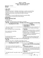
The spectrum analyser, tuned at the centre frequency of the channel, is set to the zero span
mode and a display similar to that shown in Figure 2 is obtained.
The channel level is obtained reading the peak (marker) of the displayed envelope of the
signal’s preamble.
Due to the intermittent mode transmission, the Max Hold function shall be activated, in order
to allow the spectrum analyser to catch transient signals such as cable modem return path
channel bursts. The spectrum analyser displays the highest level measured and holds it until
the trace is cleared. If different cable modems are transmitting on the same frequency with
different levels, the highest channel level will be displayed.
4.3.5.2
SCDMA transmission
In the SCDMA transmission mode, data are transmitted using a spreading code. During one
burst, spread signals from different codes are summed. The channel level of the composite
signal depends on the number of codes used at the same time. A small number of codes
results in a low channel power. An accurate measurement of the channel level can be
obtained when all possible codes are used during the same burst. The Max Hold function on
the spectrum analyser shall be activated in order to measure the channel level with
reasonable accuracy, if all possible codes are used during the measured bursts.
IEC
Figure 2 – Time domain representation of an upstream burst with marker
on the preamble of the DOCSIS signal
0738/14
Copyrighted material licensed to BR Demo by Thomson Reuters (Scientific), Inc., subscriptions.techstreet.com, downloaded on Nov-27-2014 by James Madison. No further reproduction or distribution is permitted. Uncontrolled when printe
IEC 60728-10:2014 © IEC 2014
4.3.6
IEC 60728-10:2014 © IEC 2014
Presentation of the results
The measured level shall be expressed in dB(µV) referred to 75 Ω.
4.4
4.4.1
Measurement of amplitude response variation
Background
There are a number of pieces of test equipment commercially available which are specifically
designed for this purpose. However, since these may not be generally available, the generic
method of measurement, which is described here, uses test equipment that is normally used
in service by CATV engineering staff.
Note that the proposed method of measurement cannot be used in networks during normal
operation.
4.4.2
Equipment required
The following pieces of equipment are required:
a) all equipment and cables needed for this method of measurement shall have 75 Ω
impedance (with matching attenuators if required);
b) a signal generator covering at least 3 MHz to 90 MHz. This should have an output level of
at least 114 dB(µV) and shall be capable of sweeping automatically;
c) a spectrum analyzer covering the frequency range of interest. This shall have a peak hold
and storage facility and be capable of sweeping at a slow speed (greater than 30 s for a
horizontal trace);
d) a calibrated attenuator, which can be changed in 1 dB steps. This shall be suitable for the
frequency range of interest and may be built into the spectrum analyzer;
e) a plotter or printer, which can be used to store the spectrum analyzer screen trace. This is
optional but desirable.
4.4.3
Connection of the equipment
Equipment shall be connected as shown in Figure 3.
G
A
A
NUT
P(f)
Printer
or
plotter
IEC 0739/14
Figure 3 – Arrangement of test equipment for measurement of
amplitude response variation
4.4.4
Calibration of equipment
The calibration procedure comprises the following steps.
a) Set the sweep generator to cover the frequency range to be measured and the output to
the design reference level.
b) Set the sweep time to 50 ms or less.
Copyrighted material licensed to BR Demo by Thomson Reuters (Scientific), Inc., subscriptions.techstreet.com, downloaded on Nov-27-2014 by James Madison. No further reproduction or distribution is permitted. Uncontrolled when printe
– 18 –
– 19 –
c) Connect the sweep output from the generator to the input of the spectrum analyzer.
Calibrated variable attenuators may be required if these are not built into the spectrum
analyzer.
d) Adjust the analyzer display so that the sweep is on the screen with the vertical resolution
set to 1 dB per division. The frequency span should be set to sweep at least 2 MHz above
and below the range of interest.
e) Set the resolution bandwidth (RBW) of the spectrum analyzer to 1 MHz and the video
bandwidth to 100 kHz. Adjust the analyzer sweep time to 50 s or greater.
f)
Set the display to "maximum hold" and single sweep. Clear the screen.
g) Trigger the analyzer and capture the reference sweep on screen. Record the result.
Where the spectrum analyzer has a “normalise” function this may be used at this point.
h) Increase the path loss by 1 dB and repeat step g). Repeat to obtain calibration lines from
0 dB to −10 dB.
i)
Return the attenuator to the initial setting (0 dB calibration).
4.4.5
Method of measurement
Connect the analyzer and sweep generator to the network points to be measured. Ensure
that both the sweep injection level and analyzer input levels are at the correct settings.
Repeat the single sweep and plot the result. The amplitude response variation can be read
from the final plot.
4.4.6
Presentation of the results
The amplitude response variation is expressed in dB as the maximum to minimum excursion.
The injection and measurement points shall be stated together with the frequency limits.
4.5
4.5.1
Measurement of signal to noise ratio (S D,RF /N)
General
The S D,RF /N measurement of a digital television channel is described in IEC 60728-1. The
same method can be used also on the return path. A noise bandwidth, which is applicable for
the channel under test, shall be used.
This standard describes a method of measurement for channels, which have a frequency
spectrum with a suppressed carrier (e.g. QPSK or QAM modulated channels). The signal to
noise ratio (S D,RF /N) of such a channel is the modulated channel power divided by the channel
noise power. The channel noise power is the power of the noise, which is present within the
whole bandwidth of the modulated channel.
Ingress noise may interfere with S D,RF /N measurements. To minimise the influence of ingress
noise S D,RF /N should be measured at frequencies above 15 MHz or at frequencies for which
the return service is designed.
4.5.2
Equipment required
The equipment required is a spectrum analyzer having a known noise bandwidth and a
calibrated display. The calibration accuracy should be preferably within 0,5 dB.
4.5.3
Connection of the equipment
Connect the measuring equipment to the point where the measurement shall be performed by
using a suitable connection lead. Take care to ensure correct impedance matching.
4.5.4
Measurement procedure
The measurement procedure comprises the following steps.
Copyrighted material licensed to BR Demo by Thomson Reuters (Scientific), Inc., subscriptions.techstreet.com, downloaded on Nov-27-2014 by James Madison. No further reproduction or distribution is permitted. Uncontrolled when printe
IEC 60728-10:2014 © IEC 2014
IEC 60728-10:2014 © IEC 2014
a) Tune the spectrum analyzer to the channel that shall be measured (by selecting the centre
frequency of the spectrum analyzer) and select the span and level settings to show the
whole channel.
b) Set the resolution bandwidth (RBW) of the spectrum analyzer to 30 kHz (or lower than one
tenth of the equivalent bandwidth) and the video bandwidth to 1 kHz (or lower to obtain a
smooth display). Use an RMS-type detector.
c) Read the level of the signal (S) at the centre frequency of the channel in dB(µV) or
in dB(mW) using the display line cursor if this feature is available.
d) Switch-off the channel at the input of the system or by terminating the input port with a
matched impedance. If necessary, fine-tune the centre frequency of the spectrum analyzer
to avoid ingress carriers. Otherwise, use the same settings of the spectrum analyzer as
described in b) and read the noise level (N) in dB(µV) or in dB(mW). If the signal cannot
be switched off during measurements, measure the noise level at a frequency which is
close to the channel and includes only Gaussian noise.
e) The spectrum analyzer should have a noise level which is more than 10 dB lower than the
measured noise level (N). Check it by terminating the input of the spectrum analyzer. If
the difference between N and spectrum analyzer noise is 3 dB to 10 dB, correct the value
of N as advised in Annex B.
f)
Calculate the signal to noise ratio S D,RF /N by using the following formula:
S D,RF /N = S – N
where
S D,RF /N
is the signal-to-noise ratio in dB;
S
is the signal level in dB(µV) or in dB(mW);
N
is the noise level in dB(µV) or in dB(mW).
4.5.5
Presentation of the results
The measured signal to noise ratio S D,RF /N shall be expressed in decibels.
4.6
4.6.1
Measurement of multiple interference
General
The multiple-interference consists of ingress noise and intermodulation distortion products. It
is measured with a spectrum analyzer. For 24 h, the interference spectrum is stored in a data
memory every 10 s.
As forward path signals may cause distortion products in the return band, the measurement
shall be made in a network, which has all the forward channels in operation and no signals on
the return path. Alternatively (to verify that the distortion caused by the return path signals is
insignificant), measure with all the forward and return channels, except the channel to be
measured, in operation.
As field strength at the return band frequencies depends on many variables (e.g. weekdayweekend, summer-winter, sunspot cycles, etc.), one 24 h test may not give reliable results. It
is recommended to repeat the measurement in different conditions.
In order to be able to compare multiple interference with impulse noise, both should be
measured simultaneously.
CLC/TR 50083-10-1:2009, Annex A1 gives a brief overview of multiple interference causes,
explains with more details the measurement procedure indicated below and gives ideas on
how to extract information from the collected data. For example, the computation of the
following graphs is described:
Copyrighted material licensed to BR Demo by Thomson Reuters (Scientific), Inc., subscriptions.techstreet.com, downloaded on Nov-27-2014 by James Madison. No further reproduction or distribution is permitted. Uncontrolled when printe
– 20 –
– 21 –
•
spectrograms;
•
average, minimum and maximum levels in the spectrum analyzer resolution bandwidth
versus frequency;
•
percentile analysis;
•
temporal occurrence and frequency occurrence of threshold crossing.
4.6.2
Equipment required
A spectrum analyzer with a suitable data interface is used. The measurement set-up shall be
stand-alone so that the measurement results are automatically stored during the
measurement day.
4.6.3
Connection of the equipment
Connect the measuring equipment to the point where the measurement shall be performed by
using a suitable connection lead. Take care to ensure correct impedance matching.
To verify the quality of the return path, connect the measurement equipment to the reference
point at the headend or node side.
4.6.4
Measurement procedure
Every hour of the day, measure the frequency spectrum using the following settings:
•
resolution bandwidth: 3 kHz;
•
video bandwidth: 100 Hz;
•
start and stop frequency: as required;
•
detector type: peak.
Every 10 s of the day, measure the frequency spectrum using the following settings:
•
resolution bandwidth: 30 kHz;
•
video bandwidth: 10 kHz;
•
start and stop frequency: as required;
•
detector type: peak.
4.6.5
Processing of the data
To interpret the data, the spectral power density shall first be integrated over the selected
modulation channels (e.g. 1,544 MHz according to ETSI ES 200 800 grade C). The power
level in the channel is converted to a voltage level over 75 Ω.
Determine the signal level of each channel and calculate the percentage of samples, which
fulfil the carrier-to-multiple interference ratio (C/MI) requirement for each channel.
4.6.6
Presentation of the results
The carrier-to-multiple interference ratio shall be determined for each channel separately.
Good approximation of channel availability is expressed in percent of the time, during which
the C/MI ratio (in dB) of the channel fulfils the relevant performance requirement.
In order to repeat measurements later and to be able to compare results, the following
parameters should be stated together with the results:
•
C/MI requirement used;
•
channel centre frequency;
Copyrighted material licensed to BR Demo by Thomson Reuters (Scientific), Inc., subscriptions.techstreet.com, downloaded on Nov-27-2014 by James Madison. No further reproduction or distribution is permitted. Uncontrolled when printe
IEC 60728-10:2014 © IEC 2014
IEC 60728-10:2014 â IEC 2014
ã
channel bandwidth (integration BW);
ã
signal level;
ã
measurement site;
ã
network set-up;
•
measurement date and start and stop time;
•
duration of measurement;
•
other parameters which are expected to affect the result (e.g. temperature).
4.7
4.7.1
Measurement of impulse noise
General
Impulse noise shall be measured with a digitising oscilloscope. For 24 h, samples of the
impulse noise are collected and stored in a data memory. By using the collected samples, it is
possible to calculate pulse amplitude, pulse width and interarrival distributions. These data
are used to evaluate the influence of impulse noise to different services.
The impulse noise measurement shall be made when the return path is not in use.
Impulse noise is of wide bandwidth. A high-pass filter (f –3dB = 15 MHz, –12 dB/octave, highpass) can be used at the measurement set-up input to simulate the input filter of a return path
signal receiver.
As impulse noise depends on many variables (e.g. weekday/weekend, summer/winter, etc.)
one 24-h test may not give reliable results. It is recommended to repeat the measurement in
different conditions.
In order to be able to compare impulse noise with multiple interference, both should be
measured simultaneously.
4.7.2
Equipment required
A digitising oscilloscope of negligible distortion up to 50 MHz and equipped with a suitable
data interface and input filter (as described in 4.6.1) is used. The measurement set-up shall
be stand-alone so that the measurement results are automatically stored during the
measurement day.
4.7.3
Connection of the equipment
Connect the measuring equipment to the point where the measurement shall be performed by
using a suitable connection lead. Take care to ensure correct impedance matching.
To verify the quality of the return path, connect the measurement equipment to the reference
point at the headend or node side.
4.7.4
Measurement procedure
The oscilloscope is triggered when the input signal reaches a threshold value. The threshold
value shall be higher than the noise level of the oscilloscope and higher than the ingress
noise level. A suitable threshold value triggers the oscilloscope every 2 s to 10 s. All impulse
noise traces and starting times are stored in a data memory.
Trace length shall be 100 µs. Sample time shall be 10 ns (corresponding to an upper
frequency limit of 50 MHz).
Copyrighted material licensed to BR Demo by Thomson Reuters (Scientific), Inc., subscriptions.techstreet.com, downloaded on Nov-27-2014 by James Madison. No further reproduction or distribution is permitted. Uncontrolled when printe
– 22 –
4.7.5
– 23 –
Processing of the data and presentation of the results
By using stored impulse noise data, it is possible to analyse what is the probability, that
impulse noise causes an uncorrected error in transmission.
In order to repeat measurements later and to be able to compare results, the following
parameters should be stated together with the results:
•
algorithm which was used for calculating the error probability;
•
any filter (if used at the measurement set-up input);
•
signal level;
•
measurement site;
•
network set-up;
•
measurement date and start and stop time;
•
duration of measurement;
•
other parameters which are expected to affect the result (e.g. temperature).
4.8
4.8.1
Measurement of echo ratio
General
The method described is applicable to the measurement of the amplitude and time
displacement of an echo at a specified point within a cable network by the use of a 2T-sinesquared pulse with the graticule as shown in Figure 4. From these measurements, an "echorating" is derived.
NOTE This method of measurement is mainly applicable to cable networks where analogue signal transmission is
used also in the return path.
Copyrighted material licensed to BR Demo by Thomson Reuters (Scientific), Inc., subscriptions.techstreet.com, downloaded on Nov-27-2014 by James Madison. No further reproduction or distribution is permitted. Uncontrolled when printe
IEC 60728-10:2014 © IEC 2014