AC to DC converters
Bạn đang xem bản rút gọn của tài liệu. Xem và tải ngay bản đầy đủ của tài liệu tại đây (2.79 MB, 84 trang )
Chapter 2 AC to DC Converters
Outline
2.1 Single-phase controlled rectifier
2.2 Three-phase controlled rectifier
2.3 Effect of transformer leakage inductance on rectifier circuits
2.4 Capacitor-filtered uncontrolled rectifier
2.5 Harmonics and power factor of rectifier circuits
2.6 High power controlled rectifier
2.7 Inverter mode operation of rectifier circuit
2.8 Thyristor-DC motor system
2.9 Realization of phase-control in rectifier
2.1 Single- phase controlled (controllable) rectifier
2.1.1 Single-phase half-wave controlled rectifier
Resistive load
T
VT
R
a
)
u
1
u
2
u
VT
u
d
i
d
0
ω
t
1
π
2
π
ω
t
u
2
u
g
u
d
u
VT
α
θ
0
b
)
c
)
d
)
e
)
0
0
ω
t
ω
t
ω
t
∫
+
=+==
π
α
α
α
π
ωω
π
2
cos1
45.0)cos1(
2
2
)(sin2
2
1
2
2
2d
U
U
ttdUU
(
2-1
)
Inductive (resistor-inductor) load
a
)
u
1
T
VT
R
L
u
2
u
VT
u
d
i
d
u
2
0
ω
t
1
π
2
π
ω
t
u
g
0
u
d
0
i
d
0
u
VT
0
θ
α
b
)
c
)
d
)
e
)
f
)
+
+
ω
t
ω
t
ω
t
ω
t
Basic thought process of time-domain analysis for power electronic
circuits
The time- domain behavior of a power electronic circuit is actually the
combination of consecutive transients of the different linear circuits
when the power semiconductor devices are in different states.
a
)
b
)
VT
R
L
VT
R
L
u
2
u
2
tURi
t
i
L
ω
sin2
d
d
2d
d
=+
ω
t
=
a
,
i
d
=0
)sin(
2
)sin(
2
2
)(
2
d
ϕωϕα
αω
ω
−+−−=
−−
t
Z
U
e
Z
U
i
t
L
R
(
2-2
)
(
2-3
)
Single- phase half- wave controlled rectifier with freewheeling diode
load (L is large enough) Inductive
a
)
L
T
VT
R
u
1
u
2
u
VT
u
d
VD
R
i
d
i
VD
u
2
u
d
i
d
u
VT
i
VT
I
d
I
d
ω
t
O
O
O
O
O
O
π
-
α
π
+
α
b
)
i
VD
R
ω
t
ω
t
ω
t
ω
t
ω
t
g
)
c
)
e
)
f
)
d
)
ω
T
1
Maximum forward voltage, maximum reverse voltage
Disadvantages:
–Only single pulse in one line cycle
–DC component in the transformer current
ddVT
2
II
π
απ
−
=
d
2
dVT
2
)(
2
1
ItdII
π
απ
ω
π
π
α
−
==
∫
d
2
2
dVD
2
)(
2
1
R
ItdII
π
απ
ω
π
απ
π
+
==
∫
+
ddVD
2
R
II
π
απ
+
=
(
2-5
)
(
2-6
)
(
2-7
)
(
2-8
)
2.1.2 Single- phase bridge fully-controlled rectifier
Resistive load
π
ω
t
0
0
0
i
2
u
d
i
d
b
)
c
)
d
)
u
d
(
i
d
)
α
α
R
T
u
1
u
2
a
)
i
2
a
b
VT
3
u
d
i
d
u
VT
1
,
4
ω
t
ω
t
VT
4
VT
1
VT
2
Average output (rectified) voltage:
Average output current:
For thyristor:
For transformer:
∫
+
=
+
==
π
α
αα
π
ωω
π
2
cos1
9.0
2
cos122
)(dsin2
1
2
2
2d
U
U
ttUU
(
2-9
)
(
2-10
)
2
cos1
9.0
2
cos122
22
d
d
αα
π
+
=
+
==
R
U
R
U
R
U
I
(
2-11
)
2
cos1
45.0
2
1
2
ddVT
α
+
==
R
U
II
π
απ
α
π
ωω
π
π
α
−
+==
∫
2sin
2
1
2
)(d)sin
2
(
2
1
2
2
2
VT
R
U
tt
R
U
I
(
2-12
)
π
απ
α
π
ωω
π
π
α
−
+===
∫
2sin
2
1
)()sin
2
(
1
2
2
2
2
R
U
tdt
R
U
II
(2-13)
Inductive load (L is large enough)
ω
t
ω
t
ω
t
ω
t
ω
t
ω
t
ω
t
ο
ο
ο
ο
ο
ο
ο
u
2
u
d
i
d
I
d
I
d
I
d
I
d
I
d
i
VT
1,4
i
VT
2,3
u
VT
1,4
i
2
,
b
)
R
T
u
1
u
2
a
)
i
2
a
b
VT
3
u
d
i
d
VT
4
VT
1
VT
2
Electro- motive-force (EMF) load With resistor
∫
+
===
απ
α
αα
π
ωω
π
cos9.0cos
22
)(dsin2
1
222d
UUttUU
(
2-15
)
a
)
b
)
R
E
i
d
u
d
i
d
O
E
u
d
ω
t
I
d
O
ω
t
α
θ
δ
With resistor and inductor
When L is large enough, the output voltage and current waveforms are
the same as ordinary inductive load.
When L is at a critical value
O
u
d
0
E
i
d
ω
t
ω
t
π
δ
α
θ
=
π
dmin
2
3
dmin
2
1087.2
22
I
U
I
U
L
−
×==
πω
(
2-17
)
2.1.3 Single- phase full- wave controlled rectifier
a
)
b
)
u
1
T
R
u
2
u
2
i
1
VT
1
VT
2
u
d
u
d
i
1
O
O
α
ω
t
ω
t
2.1.4 Single- phase bridge half-controlled rectifier
a)
T
a
b
R
L
O
b)
u
2
i
2
u
d
i
d
VT
1
VT
2
VD
3
VD
4
VD
R
u
2
O
u
d
i
d
I
d
O
O
O
O
O
i
2
I
d
I
d
I
d
I
d
I
d
α
ω
t
ω
t
ω
t
ω
t
ω
t
ω
t
ω
t
α
π−
α
π−
α
i
VT
1
i
VD
4
i
VT
2
i
VD
3
i
VD
R
Another single- phase bridge half-controlled rectifier
Comparison with previous circuit:
–No need for additional freewheeling diode
–Isolation is necessary between the drive circuits of the two thyristors
load
T
u
2
VT
2
VT
4
VT
1
VT
3
Summary of some important points in analysis
When analyzing a thyristor circuit, start from a diode circuit with the
same topology. The behavior of the diode circuit is exactly the same
as the thyristor circuit when firing angle is 0.
A power electronic circuit can be considered as different linear circuits
when the power semiconductor devices are in different states. The
time- domain behavior of the power electronic circuit is actually the
combination of consecutive transients of the different linear circuits.
Take different principle when dealing with different load
– For resistive load: current waveform of a resistor is the same as the
voltage waveform
–For inductive load with a large inductor: the inductor current can
be considered constant
2.2 Three- phase controlled (controllable) rectifier
2.2.1 Three- phase half- wave controlled rectifier
Resistive load, α= 0º
a
b
c
T
R
u
d
i
d
VT
2
VT
1
VT
3
u
2
O
O
O
u
ab
u
ac
O
i
VT
1
u
VT
1
ω
t
ω
t
ω
t
ω
t
ω
t
u
a
u
b
u
c
u
G
u
d
ω
t
1
ω
t
2
ω
t
3
Common-cathode connection
Natural commutation point
Resistive load, α= 30º
u
2
u
a
u
b
u
c
O
O
O
ω
t
O
ω
t
O
ω
t
u
G
u
d
u
ab
u
ac
ω
t
1
i
VT
1
u
VT
1
u
ac
ω
t
ω
t
a
b
c
T
R
u
d
i
d
VT
2
VT
1
VT
3
Resistive load, α= 60º
ω
t
u
2
u
a
u
b
u
c
O
O
O
O
u
G
u
d
i
VT
1
ω
t
ω
t
ω
t
a
b
c
T
R
u
d
i
d
VT
2
VT
1
VT
3
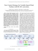
Resistive load, quantitative analysis
When α≤ 30º , load current id is continuous.
When α > 30º , load current id is discontinuous.
Average load current
Thyristor voltages
αα
π
ωω
π
α
π
α
π
cos17.1cos
2
63
)(sin2
3
2
1
22
6
5
6
2d
UUttdUU ===
∫
+
+
(
2-18
)
++=
++==
∫
+
)
6
cos(1675.0)
6
cos(1
2
23
)(sin2
3
2
1
2
6
2d
α
π
α
π
π
ωω
π
π
α
π
UttdUU
(2-19)
R
U
I
d
d
=
(
2-20
)
0
30
60
90
120
150
0
.
4
0
.
8
1
.
2
1
.
17
3
2
1
α
/(
°
)
U
d/
U
2
Inductive load, L is large enough
T
R
L
u
d
e
L
i
d
VT
3
u
d
i
a
u
a
u
b
u
c
i
b
i
c
i
d
u
ac
u
ab
u
ac
O
O
O
O
O
O
ω
t
α
u
VT
1
ω
t
ω
t
ω
t
ω
t
ω
t
a
b
c
VT
2
Thyristor voltage and currents, transformer current :
αα
π
ωω
π
α
π
α
π
cos17.1cos
2
63
)(sin2
3
2
1
22
6
5
6
2d
UUttdUU ===
∫
+
+
(
2-18
)
ddVT2
577.0
3
1
IIII ===
d
VT
VT(AV)
368.0
57.1
I
I
I ==
2RMFM
45.2 UUU ==
(
2-23
)
(
2-25
)
(
2-24
)
2.2.2 Three- phase bridge fully-controlled rectifier
Circuit diagram
Common- cathode group and common- anode group of thyristors
Numbering of the 6 thyristors indicates the trigger sequence.
b
a
c
T
n
load
i
a
i
d
u
d
VT
1
VT
3
VT
5
VT
4
VT
6
VT
2
d
2
d
1
Resistive load, α= 0º
b
a
c
T
n
load
i
a
i
d
u
d
VT
1
VT
3
VT
5
VT
4
VT
6
VT
2
d
2
d
1
u
2
u
d
1
u
d
2
u
2
L
u
d
u
ab
u
ac
u
ab
u
ac
u
bc
u
ba
u
ca
u
cb
u
ab
u
ac
u
ab
u
ac
u
bc
u
ba
u
ca
u
cb
u
ab
u
ac
I
II
III
IV
V
VI
u
a
u
c
u
b
ω
t
1
O
ω
t
O
ω
t
O
ω
t
O
ω
t
α
=
0
°
i
VT
1
u
VT
1
Resistive load, α= 30º
b
a
c
T
n
load
i
a
i
d
u
d
VT
1
VT
3
VT
5
VT
4
VT
6
VT
2
d
2
d
1