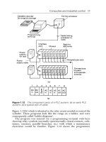
Siemens S7 200N Programmable Controller
Bạn đang xem bản rút gọn của tài liệu. Xem và tải ngay bản đầy đủ của tài liệu tại đây (2.95 MB, 606 trang )
Preface, Contents
Introducing the S7-200 Micro
PLC
1
Installing an S7-200 Micro PLC
2
Getting Started with an S7-200
Programming System
3
Basic Concepts for Programming
an S7-200 CPU
4
CPU Memory: Data Types and
Addressing Modes
5
CPU and Input/Output
Configuration
6
Setting Up Communications
Hardware and Network
Communications
7
Conventions for S7-200
Instructions
8
SIMATIC Instructions
9
IEC 1131-3 Instructions
10
Using USS Protocol Instructions
to Communicate with Drives
11
Appendices
S7-200 Specifications
A
Error Codes
B
Special Memory (SM) Bits
C
S7-200 Troubleshooting Guide
D
S7-200 Order Numbers
E
Execution Times for STL
Instructions
F
S7-200 Quick Reference
Information
G
Index
03/2000
Edition 02
S7-200
Programmable Controller
System Manual
This manual has the order number:
6ES7298-8FA21-8BH0
SIMATIC
This manual contains notices which you should observe to ensure your own personal safety, as
well as to protect the product and connected equipment. These notices are highlighted in the ma-
nual by a warning triangle and are marked as follows according to the level of danger:
!
Danger
indicates that death, severe personal injury or substantial property damage will result if proper
precautions are not taken.
!
Warning
indicates that death, severe personal injury or substantial property damage can result if proper
precautions are not taken.
!
Caution
indicates that minor personal injury or property damage can result if proper precautions are not
taken.
Note
draws your attention to particularly important information on the product, handling the product,
or to a particular part of the documentation.
Only qualified personnel should be allowed to install and work on this equipment. Qualified
persons are defined as persons who are authorized to commission, to ground, and to tag circuits,
equipment, and systems in accordance with established safety practices and standards.
Note the following:
!
Warning
This device and its components may only be used for the applications described in the catalog or
the technical description, and only in connection with devices or components from other manu-
facturers which have been approved or recommended by Siemens.
This product can only function correctly and safely if it is transported, stored, set up, and instal-
led correctly, and operated and maintained as recommended.
SIMATIC, SIMATIC NET and SIMATIC HMI are registered trademarks of
SIEMENS AG.
Third parties using for their own purposes any other names in this document which refer to
trademarks might infringe upon the rights of the trademark owners.
We have checked the contents of this manual for agreement with the
hardware and software described. Since deviations cannot be
precluded entirely, we cannot guarantee full agreement. However,
the data in this manual are reviewed regularly and any necessary
corrections included in subsequent editions. Suggestions for
improvement are welcomed.
Disclaimer of LiabilityCopyright {Siemens AG 2000 All rights reserved
The reproduction, transmission or use of this document or its
contents is not permitted without express written authority.
Offenders will be liable for damages. All rights, including rights
created by patent grant or registration of a utility model or design, are
reserved.
Siemens AG
Bereich Automatisierungs- und Antriebstechnik
Geschaeftsgebiet Industrie-Automatisierungssysteme
Postfach 4848, D-90327 Nuernberg
Siemens AG 2000
Subject to technical change.
Siemens Aktien
g
esellschaft 6ES7298-8FA21-8BH0
Notes on Safety
Qualified Personnel
Correct Usage
Trademarks
iii
S7-200 Programmable Controller System Manual
A5E00066097-02
Preface
Purpose
The S7-200 series is a line of micro-programmable logic controllers (Micro PLCs)
that can control a variety of automation applications. Compact design, low cost,
and a powerful instruction set make the S7-200 controllers a perfect solution for
controlling small applications. The wide variety of CPU sizes and voltages and the
Windows-based programming tool give you the flexibility you need to solve your
automation problems.
The S7-200 product line has been redesigned to be smaller, faster, and to have
increased functionality. The new S7-200 products are intended to replace the
previous products.
This manual provides information about installing and programming the S7-200
Micro PLCs. The
S7-200 Programmable Controller System Manual
includes the
following topics:
• Installing and wiring
• Understanding the CPU operations, data types and addressing modes, scan
cycle, password protection, and network communication
• Specifications
• Descriptions and examples for the SIMATIC and IEC 11313 programming
instructions
• Using the USS Protocol Instructions to communicate with drives
• Typical execution times for SIMATIC STL instructions
Audience
This manual is designed for engineers, programmers, installers, and electricians
who have a general knowledge of programmable logic controllers.
Preface
iv
S7-200 Programmable Controller System Manual
A5E00066097-02
Scope of the Manual
The information contained in this manual pertains in particular to the following
products:
• S7-200 CPU models: CPU 221, CPU 222, and CPU 224 (firmware release 1.1),
and CPU 226 (firmware release 1.0).
• STEP 7Micro/WIN 32, version 3.1, a 32-bit programming software package for
Windows 95, Windows 98, and the Windows NT environment
• STEP 7Micro/WIN 32 Toolbox, a 32-bit programming software package for the
Windows 95, Windows 98, and the Windows NT 4.0 environment.
STEP 7Micro/WIN 32 Toolbox is designed for customers who use the S7-200
CPU with other microsystem components (such as the TP070 Touch Panel or a
MicroMaster drive).
Agency Approvals
The SIMATIC S7-200 series meets the following regulations:
• European Community (CE) Low Voltage Directive 73/23/EEC
• European Community (CE) EMC Directive 89/336/EEC
• Underwriters Laboratories, Inc.: UL 508 Listed (Industrial Control Equipment)
• Canadian Standards Association: CSA C22.2 Number 142 Certified (Process
Control Equipment)
• Factory Mutual Research: FM Class I, Division 2, Groups A, B, C, & D
Hazardous Locations, T4A and Class I, Zone 2, IIC, T4.
Refer to Appendix A for compliance information.
Related Information
Refer to the following for more detailed information about selected topics:
• STEP 7Micro/WIN 32 CD/disk: provides online help, the
STEP 7Micro/WIN
Getting Started
(a printable online manual), and Tips and Tricks projects.
• STEP 7Micro/WIN 32 Toolbox CD: provides the TP070 Touch Panel
Configuration Software, USS Protocol Instructions, online help, the
STEP 7Micro/WIN Getting Started
(a printable online manual), and Tips and
Tricks projects.
• Process Field Bus (PROFIBUS) standard (EN 50170): describes the standard
protocol for the S7-200 DP communication capability.
•
TD 200 Operator Interface User Manual:
describes how to install and use the
TD 200 with an S7-200 programmable logic controller.
Preface
v
S7-200 Programmable Controller System Manual
A5E00066097-02
How to Use This Manual
If you are a first-time (novice) user of S7-200 Micro PLCs, you should read the
entire
S7-200 Programmable Controller System Manual
. If you are an experienced
user, refer to the manual table of contents or index to find specific information.
The
S7-200 Programmable Controller System Manual
is organized according to
the following topics:
• “Introducing the S7-200 Micro PLC” (Chapter 1) provides an overview of some
of the features of the equipment.
• “Installing an S7-200 Micro PLC” (Chapter 2) provides procedures, dimensions,
and basic guidelines for installing the S7-200 CPU modules and expansion I/O
modules.
• “Getting Started with an S7-200 Programming System” (Chapter 3) describes
how to set up an S7-200 programming system.
• “Basic Concepts for Programming an S7-200 CPU” (Chapter 4), “CPU Memory:
Data Types and Addressing Modes” (Chapter 5), and “CPU and Input/Output
Control” (Chapter 6) provide information about how the S7-200 CPU processes
data and executes your program.
• “Setting Up Communications Hardware and Network Communications”
(Chapter 7) provides information about how to install and remove
communications hardware and how to connect the S7-200 CPU to different
types of networks.
• “Conventions for S7-200 Instructions” (Chapter 8) provides an overview of the
different programming language concepts and terminology.
• “SIMATIC Instructions” (Chapter 9) provides descriptions and examples of
SIMATIC LAD, FBD, and STL programming instructions.
• “IEC 11313 Instructions” (Chapter 10) provides descriptions and examples of
IEC 11313 LAD and FBD programming instructions.
• “Using USS Protocol Instructions to Communicate with Drives” (Chapter 11)
provides descriptions and examples of USS Protocol Instructions and
information about how to use these instructions to communicate with drives.
Additional information (such as the equipment specifications, error code
descriptions, troubleshooting, and STL instruction execution times) are provided in
the appendices.
Preface
vi
S7-200 Programmable Controller System Manual
A5E00066097-02
Additional Assistance
For assistance in answering technical questions, for training on this product, or for
ordering, contact your Siemens distributor or sales office.
For Internet information about Siemens products and services, technical support,
or FAQs (frequently asked questions) and application tips, use the following
Internet addresses:
for general Siemens information
for S7-200 product information
vii
S7-200 Programmable Controller System Manual
A5E00066097-02
Contents
1 Introducing the S7-200 Micro PLC 1-1. . . . . . . . . . . . . . . . . . . . . . . . . . . . . . . . . . . . . . .
1.1 Comparing the Features of the S7-200 Micro PLCs 1-2. . . . . . . . . . . . . . . . . .
1.2 Major Components of the S7-200 Micro PLC 1-5. . . . . . . . . . . . . . . . . . . . . . . .
1.3 Maximum I/O Configurations 1-7. . . . . . . . . . . . . . . . . . . . . . . . . . . . . . . . . . . . . .
2 Installing an S7-200 PLC 2-1. . . . . . . . . . . . . . . . . . . . . . . . . . . . . . . . . . . . . . . . . . . . . . . .
2.1 Panel Layout Considerations 2-2. . . . . . . . . . . . . . . . . . . . . . . . . . . . . . . . . . . . . .
2.2 Installing and Removing an S7-200 Micro PLC or Expansion Module 2-6. . .
2.3 Installing the Field Wiring 2-9. . . . . . . . . . . . . . . . . . . . . . . . . . . . . . . . . . . . . . . . .
2.4 Using Suppression Circuits 2-16. . . . . . . . . . . . . . . . . . . . . . . . . . . . . . . . . . . . . . .
2.5 Power Considerations 2-18. . . . . . . . . . . . . . . . . . . . . . . . . . . . . . . . . . . . . . . . . . . .
3 Getting Started with an S7-200 Programming System 3-1. . . . . . . . . . . . . . . . . . . . .
3.1 Overview 3-2. . . . . . . . . . . . . . . . . . . . . . . . . . . . . . . . . . . . . . . . . . . . . . . . . . . . . .
3.2 Quick Start for STEP 7-Micro/WIN 32 3-3. . . . . . . . . . . . . . . . . . . . . . . . . . . . . .
3.3 How Do I Set Up Communications Using the PC/PPI Cable? 3-5. . . . . . . . . .
3.4 How Do I Complete the Communications Connection? 3-9. . . . . . . . . . . . . . .
3.5 How Do I Change the Communications Parameters for My PLC? 3-10. . . . . .
4 Basic Concepts for Programming an S7-200 CPU 4-1. . . . . . . . . . . . . . . . . . . . . . . . .
4.1 Guidelines for Designing a Micro PLC System 4-2. . . . . . . . . . . . . . . . . . . . . . .
4.2 Concepts of an S7-200 Program 4-5. . . . . . . . . . . . . . . . . . . . . . . . . . . . . . . . . .
4.3 Concepts of the S7-200 Programming Languages and Editors 4-6. . . . . . . . .
4.4 Understanding the Differences between SIMATIC and
IEC 1131-3 Instructions 4-10. . . . . . . . . . . . . . . . . . . . . . . . . . . . . . . . . . . . . . . . . .
4.5 Basic Elements for Constructing a Program 4-18. . . . . . . . . . . . . . . . . . . . . . . . .
4.6 Understanding the Scan Cycle of the CPU 4-22. . . . . . . . . . . . . . . . . . . . . . . . . .
4.7 Selecting the Mode of Operation for the CPU 4-25. . . . . . . . . . . . . . . . . . . . . . .
4.8 Creating a Password for the CPU 4-27. . . . . . . . . . . . . . . . . . . . . . . . . . . . . . . . . .
4.9 Debugging and Monitoring Your Program 4-30. . . . . . . . . . . . . . . . . . . . . . . . . . .
4.10 Editing in RUN Mode 4-39. . . . . . . . . . . . . . . . . . . . . . . . . . . . . . . . . . . . . . . . . . . .
4.11 Background Time 4-42. . . . . . . . . . . . . . . . . . . . . . . . . . . . . . . . . . . . . . . . . . . . . . .
4.12 Error Handling for the S7-200 CPU 4-43. . . . . . . . . . . . . . . . . . . . . . . . . . . . . . . .
Contents
viii
S7-200 Programmable Controller System Manual
A5E00066097-02
5 CPU Memory: Data Types and Addressing Modes 5-1. . . . . . . . . . . . . . . . . . . . . . . . .
5.1 Direct Addressing of the CPU Memory Areas 5-2. . . . . . . . . . . . . . . . . . . . . . .
5.2 SIMATIC Indirect Addressing of the CPU Memory Areas 5-13. . . . . . . . . . . . . .
5.3 Memory Retention for the S7-200 CPU 5-15. . . . . . . . . . . . . . . . . . . . . . . . . . . . .
5.4 Using Your Program to Store Data Permanently 5-20. . . . . . . . . . . . . . . . . . . . .
5.5 Using a Memory Cartridge to Store Your Program 5-22. . . . . . . . . . . . . . . . . . .
6 CPU and Input/Output Configuration 6-1. . . . . . . . . . . . . . . . . . . . . . . . . . . . . . . . . . . . .
6.1 Local I/O and Expansion I/O 6-2. . . . . . . . . . . . . . . . . . . . . . . . . . . . . . . . . . . . . .
6.2 Using the Selectable Input Filter to Provide Noise Rejection 6-4. . . . . . . . . . .
6.3 Pulse Catch 6-5. . . . . . . . . . . . . . . . . . . . . . . . . . . . . . . . . . . . . . . . . . . . . . . . . . . .
6.4 Using the Output Table to Configure the States of the Outputs 6-8. . . . . . . . .
6.5 Analog Input Filter 6-9. . . . . . . . . . . . . . . . . . . . . . . . . . . . . . . . . . . . . . . . . . . . . . .
6.6 High-Speed I/O 6-10. . . . . . . . . . . . . . . . . . . . . . . . . . . . . . . . . . . . . . . . . . . . . . . . .
6.7 Analog Adjustments 6-13. . . . . . . . . . . . . . . . . . . . . . . . . . . . . . . . . . . . . . . . . . . . .
7 Setting Up Communications Hardware and Network Communications 7-1. . . . . .
7.1 What Are My Communication Choices? 7-2. . . . . . . . . . . . . . . . . . . . . . . . . . . .
7.2 Installing and Removing Communication Interfaces 7-7. . . . . . . . . . . . . . . . . .
7.3 Selecting and Changing Parameters 7-9. . . . . . . . . . . . . . . . . . . . . . . . . . . . . . .
7.4 Communicating With Modems 7-16. . . . . . . . . . . . . . . . . . . . . . . . . . . . . . . . . . . .
7.5 Network Overview 7-27. . . . . . . . . . . . . . . . . . . . . . . . . . . . . . . . . . . . . . . . . . . . . . .
7.6 Network Components 7-32. . . . . . . . . . . . . . . . . . . . . . . . . . . . . . . . . . . . . . . . . . . .
7.7 Using the PC/PPI Cable with Other Devices and Freeport 7-36. . . . . . . . . . . .
7.8 Network Performance 7-42. . . . . . . . . . . . . . . . . . . . . . . . . . . . . . . . . . . . . . . . . . . .
8 Conventions for S7-200 Instructions 8-1. . . . . . . . . . . . . . . . . . . . . . . . . . . . . . . . . . . . .
8.1 Concepts and Conventions For STEP 7-Micro/WIN 32 Programming 8-2. . .
8.2 Valid Ranges for the S7-200 CPUs 8-7. . . . . . . . . . . . . . . . . . . . . . . . . . . . . . . .
9 SIMATIC Instructions 9-1. . . . . . . . . . . . . . . . . . . . . . . . . . . . . . . . . . . . . . . . . . . . . . . . . . .
9.1 SIMATIC Bit Logic Instructions 9-2. . . . . . . . . . . . . . . . . . . . . . . . . . . . . . . . . . . .
9.2 SIMATIC Compare Instructions 9-10. . . . . . . . . . . . . . . . . . . . . . . . . . . . . . . . . . .
9.3 SIMATIC Timer Instructions 9-15. . . . . . . . . . . . . . . . . . . . . . . . . . . . . . . . . . . . . . .
9.4 SIMATIC Counter Instructions 9-23. . . . . . . . . . . . . . . . . . . . . . . . . . . . . . . . . . . . .
9.5 SIMATIC Clock Instructions 9-71. . . . . . . . . . . . . . . . . . . . . . . . . . . . . . . . . . . . . . .
9.6 SIMATIC Integer Math Instructions 9-73. . . . . . . . . . . . . . . . . . . . . . . . . . . . . . . .
9.7 SIMATIC Real Math Instructions 9-82. . . . . . . . . . . . . . . . . . . . . . . . . . . . . . . . . . .
9.8 SIMATIC Numerical Functions Instructions 9-85. . . . . . . . . . . . . . . . . . . . . . . . . .
Contents
ix
S7-200 Programmable Controller System Manual
A5E00066097-02
9.9 SIMATIC Move Instructions 9-102. . . . . . . . . . . . . . . . . . . . . . . . . . . . . . . . . . . . . . .
9.10 SIMATIC Table Instructions 9-107. . . . . . . . . . . . . . . . . . . . . . . . . . . . . . . . . . . . . . .
9.11 SIMATIC Logical Operations Instructions 9-114. . . . . . . . . . . . . . . . . . . . . . . . . . .
9.12 SIMATIC Shift and Rotate Instructions 9-120. . . . . . . . . . . . . . . . . . . . . . . . . . . . .
9.13 SIMATIC Conversion Instructions 9-130. . . . . . . . . . . . . . . . . . . . . . . . . . . . . . . . . .
9.14 SIMATIC Program Control Instructions 9-145. . . . . . . . . . . . . . . . . . . . . . . . . . . . .
9.15 SIMATIC Interrupt and Communications Instructions 9-169. . . . . . . . . . . . . . . . .
9.16 SIMATIC Logic Stack Instructions 9-197. . . . . . . . . . . . . . . . . . . . . . . . . . . . . . . . .
10 IEC 1131-3 Instructions 10-1. . . . . . . . . . . . . . . . . . . . . . . . . . . . . . . . . . . . . . . . . . . . . . . . .
10.1 IEC Bit Logic Instructions 10-2. . . . . . . . . . . . . . . . . . . . . . . . . . . . . . . . . . . . . . . . .
10.2 IEC Compare Instructions 10-8. . . . . . . . . . . . . . . . . . . . . . . . . . . . . . . . . . . . . . . .
10.3 IEC Timer Instructions 10-11. . . . . . . . . . . . . . . . . . . . . . . . . . . . . . . . . . . . . . . . . . .
10.4 IEC Counter Instructions 10-15. . . . . . . . . . . . . . . . . . . . . . . . . . . . . . . . . . . . . . . . .
10.5 IEC Math Instructions 10-18. . . . . . . . . . . . . . . . . . . . . . . . . . . . . . . . . . . . . . . . . . . .
10.6 IEC Numerical Functions Instructions 10-21. . . . . . . . . . . . . . . . . . . . . . . . . . . . . .
10.7 IEC Move Instructions 10-23. . . . . . . . . . . . . . . . . . . . . . . . . . . . . . . . . . . . . . . . . . .
10.8 IEC Logic Instructions 10-25. . . . . . . . . . . . . . . . . . . . . . . . . . . . . . . . . . . . . . . . . . . .
10.9 IEC Shift and Rotate Instructions 10-27. . . . . . . . . . . . . . . . . . . . . . . . . . . . . . . . . .
10.10 IEC Conversion Instructions 10-30. . . . . . . . . . . . . . . . . . . . . . . . . . . . . . . . . . . . . .
11 Using USS Protocol Instructions to Communicate with Drives 11-1. . . . . . . . . . . . .
11.1 USS Protocol Instruction Requirements 11-2. . . . . . . . . . . . . . . . . . . . . . . . . . . .
11.2 Programming Sequence 11-4. . . . . . . . . . . . . . . . . . . . . . . . . . . . . . . . . . . . . . . . . .
11.3 USS Protocol Instructions 11-5. . . . . . . . . . . . . . . . . . . . . . . . . . . . . . . . . . . . . . . .
11.4 Connecting the Drives 11-17. . . . . . . . . . . . . . . . . . . . . . . . . . . . . . . . . . . . . . . . . . .
11.5 Drive Setup 11-18. . . . . . . . . . . . . . . . . . . . . . . . . . . . . . . . . . . . . . . . . . . . . . . . . . . . .
Contents
x
S7-200 Programmable Controller System Manual
A5E00066097-02
A S7-200 Specifications A-1. . . . . . . . . . . . . . . . . . . . . . . . . . . . . . . . . . . . . . . . . . . . . . . . . . .
A.1 General Technical Specifications A-2. . . . . . . . . . . . . . . . . . . . . . . . . . . . . . . . . .
A.2 Specifications for the CPU 221, Firmware Release 1.1 A-6. . . . . . . . . . . . . . .
A.3 Specifications for the CPU 222, Firmware Release 1.1 A-11. . . . . . . . . . . . . . .
A.4 Specifications for the CPU 224, Firmware Release 1.1 A-16. . . . . . . . . . . . . . .
A.5 Specifications for the CPU 226 A-21. . . . . . . . . . . . . . . . . . . . . . . . . . . . . . . . . . . .
A.6 Specifications for the EM 221 Digital Input Module A-26. . . . . . . . . . . . . . . . . . .
A.7 Specifications for the EM 222 Digital Output Modules A-28. . . . . . . . . . . . . . . .
A.8 Specifications for the EM 223 Digital Combination Modules,
4 Inputs/4 Outputs A-30. . . . . . . . . . . . . . . . . . . . . . . . . . . . . . . . . . . . . . . . . . . . . . .
A.9 Specifications for the EM 223 Digital Combination Modules,
8 Inputs/8 Outputs A-33. . . . . . . . . . . . . . . . . . . . . . . . . . . . . . . . . . . . . . . . . . . . . .
A.10 Specifications for the EM 223 Digital Combination Modules,
16 Inputs/16 Outputs A-36. . . . . . . . . . . . . . . . . . . . . . . . . . . . . . . . . . . . . . . . . . . .
A.11 Specifications for the EM 231, EM 232, and EM 235 Analog Input,
Output, and Combination Modules A-39. . . . . . . . . . . . . . . . . . . . . . . . . . . . . . . . .
A.12 Specifications for the EM 277 PROFIBUS-DP Module A-50. . . . . . . . . . . . . . . .
A.13 Specifications for EM 231 Thermocouple, EM 231 RTD Modules A-67. . . . . .
A.14 CP 243-2 Communications Processor A-85. . . . . . . . . . . . . . . . . . . . . . . . . . . . . .
A.15 Optional Cartridges A-88. . . . . . . . . . . . . . . . . . . . . . . . . . . . . . . . . . . . . . . . . . . . .
A.16 I/O Expansion Cable A-89. . . . . . . . . . . . . . . . . . . . . . . . . . . . . . . . . . . . . . . . . . . . .
A.17 PC/PPI Cable A-90. . . . . . . . . . . . . . . . . . . . . . . . . . . . . . . . . . . . . . . . . . . . . . . . . . .
A.18 Input Simulators A-93. . . . . . . . . . . . . . . . . . . . . . . . . . . . . . . . . . . . . . . . . . . . . . . . .
B Error Codes B-1. . . . . . . . . . . . . . . . . . . . . . . . . . . . . . . . . . . . . . . . . . . . . . . . . . . . . . . . . . . .
B.1 Fatal Error Codes and Messages B-2. . . . . . . . . . . . . . . . . . . . . . . . . . . . . . . . . .
B.2 Run-Time Programming Problems B-3. . . . . . . . . . . . . . . . . . . . . . . . . . . . . . . . .
B.3 Compile Rule Violations B-4. . . . . . . . . . . . . . . . . . . . . . . . . . . . . . . . . . . . . . . . . .
C Special Memory (SM) Bits C-1. . . . . . . . . . . . . . . . . . . . . . . . . . . . . . . . . . . . . . . . . . . . . . .
D S7-200 Troubleshooting Guide D-1. . . . . . . . . . . . . . . . . . . . . . . . . . . . . . . . . . . . . . . . . .
E S7-200 Order Numbers E-1. . . . . . . . . . . . . . . . . . . . . . . . . . . . . . . . . . . . . . . . . . . . . . . . . .
F Execution Times for STL Instructions F-1. . . . . . . . . . . . . . . . . . . . . . . . . . . . . . . . . . . .
G S7-200 Quick Reference Information G-1. . . . . . . . . . . . . . . . . . . . . . . . . . . . . . . . . . . . .
Index Index-1. . . . . . . . . . . . . . . . . . . . . . . . . . . . . . . . . . . . . . . . . . . . . . . . . . . . . . . . . . . . . . . .
1-1
S7-200 Programmable Controller System Manual
A5E00066097-02
Introducing the S7-200 Micro PLC
The S7-200 series is a line of micro-programmable logic controllers (Micro PLCs)
that can control a variety of automation applications. Figure 1-1 shows an S7-200
Micro PLC. The compact design, expandability, low cost, and powerful instruction
set of the S7-200 Micro PLC make a perfect solution for controlling small
applications. In addition, the wide variety of CPU sizes and voltages provides you
with the flexibility you need to solve your automation problems.
Figure 1-1 S7-200 Micro PLC
Chapter Overview
Section Description Page
1.1 Comparing the Features of the S7-200 Micro PLCs 1-2
1.2 Major Components of the S7-200 Micro PLC 1-5
1.3 Maximum I/O Configurations 1-7
1
Introducing the S7-200 Micro PLC
1-2
S7-200 Programmable Controller System Manual
A5E00066097-02
1.1 Comparing the Features of the S7-200 Micro PLCs
Equipment Requirements
Figure 1-2 shows the basic S7-200 Micro PLC system, which includes an S7-200
CPU, a personal computer, STEP 7-Micro/WIN 32, version 3.1 programming
software, and a communications cable.
In order to use a personal computer (PC), you must have one of the following:
• A PC/PPI cable
• A communications processor (CP) and multipoint interface (MPI) cable
• A multipoint interface (MPI) card. A communications cable is provided with the
MPI card.
S7-200 CPU
PC/PPI Cable
Computer
STEP 7-Micro/WIN 32
Figure 1-2 Components of an S7-200 Micro PLC System
Capabilities of the S7-200 CPUs
The S7-200 family includes a wide variety of CPUs. This variety provides a range
of features to aid in designing a cost-effective automation solution. Table 1-1
provides a summary of the major features of the S7-200 CPUs, firmware
release 1.1.
Introducing the S7-200 Micro PLC
1-3
S7-200 Programmable Controller System Manual
A5E00066097-02
Table 1-1 Summary of the S7-200 CPU
Feature CPU 221 CPU 222 CPU 224 CPU 226
Physical Size of Unit
90 mm x 80 mm x
62 mm
90 mm x 80 mm x
62 mm
120.5 mm x
80 mm x 62 mm
190 mm x
80 mm x 62 mm
Memory
Program 2048 words 2048 words 4096 words 4096 words
User data 1024 words 1024 words 2560 words 2560 words
User program storage EEPROM EEPROM EEPROM EEPROM
Data backup
(super capacitor)
50 hours typical 50 hours typical 190 hours typical 190 hours typical
Local I/O
Local I/O 6 In/4 Out 8 In/6 Out 14 In/10 Out 24 In/16 Out
Number of expansion modules none 2 modules 7 modules 7 modules
Total I/O
Digital I/O image size 256
(128 In/128 Out)
256
(128 In/128 Out)
256
(128 In/128 Out)
256
(128 In/128 Out)
Analog I/O image size none 16 In/16 Out 32 In/32 Out 32 In/32 Out
Actual I/O count that can be realized with each CPU may be limited by image register size, module count, 5V power, and
the physical number of I/O points on each product. See Section 1.3.
Instructions
Boolean execution speed at 33
MHz
0.37µs/
instruction
0.37 µs/
instruction
0.37 µs/
instruction
0.37 µs/
instruction
I/O Image Register 128 I and 128 Q 128 I and 128 Q 128 I and 128 Q 128 I and 128 Q
Internal relays 256 256 256 256
Counters/Timers 256/256 256/256 256/256 256/256
Word In / Word Out None 16/16 32/32 32/32
Sequential control relays 256 256 256 256
For/Next loops Yes Yes Yes Yes
Integer math (+ - * /) Yes Yes Yes Yes
Real math (+ - * /) Yes Yes Yes Yes
Enhanced Features
Built-in high-speed counter 4 H/W (20 KHz) 4 H/W (20 KHz) 6 H/W (20 KHz) 6 H/W (20 KHz)
Analog adjustments 1 1 2 2
Pulse outputs 2 (20 KHz,
DC only)
2 (20 KHz,
DC only)
2 (20 KHz,
DC only)
2 (20 KHz,
DC only)
Communication interrupts 1 transmit/
2 receive
1 transmit/
2 receive
1 transmit/
2 receive
2 transmit/
4 receive
Timed interrupts 2
(1 ms to 255 ms)
2
(1 ms to 255 ms)
2
(1 ms to 255 ms)
2
(1 ms to 255 ms)
Hardware input interrupts 4, input filter 4, input filter 4, input filter 4, input filter
Real-time clock Yes (cartridge) Yes (cartridge) Yes (built-in) Yes (built-in)
Password protection Yes Yes Yes Yes
Introducing the S7-200 Micro PLC
1-4
S7-200 Programmable Controller System Manual
A5E00066097-02
Table 1-1 Summary of the S7-200 CPU
Communications
Number of comm ports: 1 (RS-485) 1 (RS-485) 1 (RS-485) 2 (RS-485)
Protocols supported
Port 0:
Port 1:
PPI, DP/T, Freeport
N/A
PPI, DP/T, Freeport
N/A
PPI,DP/T, Freeport
N/A
PPI,DP/T, Freeport
PPI, DP/T, Freeport
PROFIBUS peer-to-peer (NETR/NETW) (NETR/NETW) (NETR/NETW) (NETR/NETW)
Introducing the S7-200 Micro PLC
1-5
S7-200 Programmable Controller System Manual
A5E00066097-02
1.2 Major Components of the S7-200 Micro PLC
An S7-200 Micro PLC consists of an S7-200 CPU alone or with a variety of
optional expansion modules.
S7-200 CPU
The S7-200 CPU combines a central processing unit (CPU), power supply, and
discrete I/O points into a compact, stand-alone device.
• The CPU executes the program and stores the data for controlling the
automation task or process.
• The digital inputs and outputs are the system control points: the inputs monitor
the signals from the field devices (such as sensors and switches), and the
outputs control pumps, motors, or other devices in your process.
• The power supply provides electrical power for the CPU and for any expansion
module that is connected.
• The communications port(s) allow you to connect the CPU to a programming
device or to other devices.
• Status lights provide visual information about the CPU mode (RUN or STOP),
the current state of the local I/O, and whether a system fault has been
detected.
• Additional I/O points can be added to the CPU with expansion modules. (The
CPU 221 is not expandable.)
• Higher performance communications can be added with expansion modules.
• Some CPUs provide a real-time clock as a built-in feature, while other CPUs
have an optional real-time clock cartridge.
• An optional plug-in serial EEPROM cartridge provides a means to store CPU
programs and transfer programs from one CPU to another.
• An optional plug-in battery cartridge provides extended retention of data
memory in RAM.
Introducing the S7-200 Micro PLC
1-6
S7-200 Programmable Controller System Manual
A5E00066097-02
Figure 1-3 shows the S7-200 CPU.
Top terminal door
Power terminal
Output terminal
Front access door
Mode switch
Potentiometer
Expansion I/O connection
Bottom terminal door
Input terminal
Sensor power
Status LEDs
Cartridge
Communication
Port
Figure 1-3 S7-200 CPU
Expansion Modules
The S7-200 CPU provides a certain number of local I/O. Adding an expansion
module provides additional input or output points (see Figure 1-4).
Figure 1-4 CPU with an Expansion Module
Introducing the S7-200 Micro PLC
1-7
S7-200 Programmable Controller System Manual
A5E00066097-02
1.3 Maximum I/O Configurations
The maximum I/O configuration for each CPU system is subject to the following
limits:
• Module count:
CPU 221: no expansion available
CPU 222: maximum of 2 expansion modules
CPU 224 and CPU 226: maximum of 7 expansion modules
No more than 2 of the 7 modules can be intelligent expansion modules
(EM 277 PROFIBUS-DP modules)
• Digital Image Register size: The logical space that each CPU allows for digital
I/O is 128 inputs and 128 outputs. Some physical points cannot be realized in
this logical space because this space is allocated in blocks of 8 points. An
8-point block may not be completely realized by a specific module. For
example, the CPU 224 with 10 actual outputs consumes 16 points of logical
output space. A 4-input/4-output module consumes 8 inputs and 8 outputs of
logical space. At the time of printing of this manual, there is no combination of
current release CPU and I/O modules that causes this item to be a limit. It can
be a limit in systems including prior release CPU 22x or future release products.
• Analog Image Register size: The logical space allowed for analog I/O is:
CPU 222: 16 inputs and 16 outputs
CPU 224 and CPU 226: 32 inputs and 32 outputs
• 5V power budget: The maximum 5V current supplied by each CPU is listed in
Table 1-2. Total current of all expansion modules in the system cannot exceed
this budget. See Section 2.5 for further information on power considerations.
Table 1-3 shows the maximum I/O configuration allowed for each S7-200 CPU.
Introducing the S7-200 Micro PLC
1-8
S7-200 Programmable Controller System Manual
A5E00066097-02
Table 1-2 Current Supplied by S7-200 CPU
CPU 22x
5 VDC Current Supplied
for Expansion I/O - ma
Expansion Module
5 VDC Current Consumption - ma
CPU 222 340 EM 221 DI8 x DC24V 30
CPU 224
CPU 226
660
1000
EM 222 DO8 x DC24V 50
CPU 226 1000
EM 222 DO8 x Rly 40
EM 223 DI4/DO4 x DC24V 40
EM 223 DI4/DO4 x DC24V/Rly 40
EM 223 DI8/DO8 x DC24V 80
EM 223 DI8/DO8 x DC24V/Rly 80
EM 223 DI16/DO16 x DC24V 160
EM 223 DI16/DO16 x DC24V/Rly 150
EM 231 AI4 x 12 Bit 20
EM 231 AI4 x Thermocouple 60
EM 231 AI4 x RTD 60
EM 232 AQ2 x 12 Bit 20
EM 235 AI4I/AQ1 x 12 Bit 30
EM 277 PROFIBUS-DP 150
Introducing the S7-200 Micro PLC
1-9
S7-200 Programmable Controller System Manual
A5E00066097-02
Table 1-3 Maximum I/O Configurations for S7-200 CPUs
Module 5V ma
Digital
Inputs
Digital
Outputs
Analog
Inputs
Analog
Outputs
CPU 221 No expansion possible
CPU 222
Max Digital In/Out
CPU
2 x EM 223 DI16/DO16 x DC24V
or
2 x EM 223 DI16/DO16 x DC24V/Rly
Total =
+340
-320 or
-300
>0
8
32
40
6
32
38
Max Analog In
CPU
2 x EM 235 AI4/AQ1
Total =
+340
-60
>0
8
8
6
6
8
8
2
2
Max Analog Out
CPU
2 x EM 232 AQ2
Total =
+340
-40
>0
8
8
6
6
0
0
4
4
CPU 224
Max Digital In/Rly Out
CPU
4 x EM 223 DI16/DO16 x DC24V/Rly
2 x EM 221 DI8 x DC24V
Total =
+660
-600
-60
=0
14
64
16
94
10
64
74
Max Digital In/DC Out
CPU
4 x EM 223 DI16/DO16 x DC24V
Total =
+660
-640
>0
14
64
78
10
64
74
Digital In/Max Rly Out
CPU
4 x EM 223 DI16/DO16 x DC24V/Rly
1 x EM 222 DO8 x Rly
Total =
+660
-600
-40
>0
14
64
78
10
64
8
82
CPU 226
Max Digital In/Rly Out
CPU
6 x EM 223 DI16/DO16 x DC24V/Rly
1 x EM 223 DI8/DO8 x DC24V/Rly
Total =
+1000
-900
-80
>0
24
96
8
128
16
96
8
120
Max Digital In/DC Out
CPU
6 x EM 223 DI16/DO16 x DC24V
1 x EM 221 DI8 x DC24V
Total =
+1000
-960
-30
>0
24
96
8
128
16
96
112
CPU 224 or CPU 226
Max Analog In
CPU
7 x EM 235 AI4/AQ1
Total =
>660
-210
>0
14 (24)
14 (24)
10 (16)
10 (16)
28
28
7
7
Max Analog Out
CPU
7 x EM 232 AQ2
Total =
>660
-140
>0
14 (24)
14 (24)
10 (16)
10 (16)
0
0
14
14
Introducing the S7-200 Micro PLC
1-10
S7-200 Programmable Controller System Manual
A5E00066097-02
2-1
S7-200 Programmable Controller System Manual
A5E00066097-02
Installing an S7-200 PLC
The installation of the S7-200 equipment is designed to be easy. You can use the
mounting holes to attach the modules to a panel, or you can use the built-in clips to
mount the modules onto a standard (DIN) rail. The small size of the S7-200 allows
you to make efficient use of space.
This chapter provides guidelines for installing and wiring your S7-200 system.
Chapter Overview
Section Description Page
2.1 Panel Layout Considerations 2-2
2.2 Installing and Removing an S7-200 Micro PLC or Expansion
Module
2-6
2.3 Installing the Field Wiring 2-9
2.4 Using Suppression Circuits 2-16
2.5 Power Considerations 2-18
2
Installing an S7-200 PLC
2-2
S7-200 Programmable Controller System Manual
A5E00066097-02
2.1 Panel Layout Considerations
Installation Configuration
You can install an S7-200 either on a panel or on a standard rail. You can mount
the S7-200 either horizontally or vertically. You can connect the S7-200 to
expansion modules by one of these methods:
• A flexible ribbon cable with mating connector is built into the I/O module for
easy connection to the PLC or another expansion module.
• An I/O expansion cable is also available to add flexibility to your mounting
configuration.
Figure 2-1 shows a typical configuration for these types of installations.
S7-200 I/O I/O
Panel mounting Standard rail mounting
S7-200 I/O I/O
I/O I/O
Figure 2-1 Mounting Configurations
Clearance Requirements for Installing an S7-200 PLC
Use the following guidelines as you plan your installation:
• The S7-200 CPU and expansion modules are designed for natural convection
cooling. You must provide a clearance of at least 25 mm (1 in.), both above and
below the units, for proper cooling. See Figure 2-2. Continuous operation of all
electronic products at maximum ambient temperature and load reduces their
life.
• For vertical mounting, the maximum ambient temperature is reduced by 10° C.
The CPU should be mounted below any expansion modules. If you are
mounting on a vertical DIN rail, you should use the DIN rail stop.
• Allow 75 mm (3 in.) for mounting depth. See Figure 2-2.
• Be sure to allow enough space in your mounting design to accommodate the
I/O wiring and communication cable connections.
Installing an S7-200 PLC
2-3
S7-200 Programmable Controller System Manual
A5E00066097-02
75 mm
(3 in.)
S7-200
Front of the
enclosure
25 mm
(1 in.)
25 mm
(1 in.)
Clearance for cooling
Front View
Side View
S7-200 I/O
Mounting
surface
Figure 2-2 Horizontal and Vertical Clearance Requirements for Installing an S7-200 PLC
Standard Rail Requirements
The S7-200 CPU and expansion modules can be installed on a standard (DIN) rail
(DIN EN 50 022). Figure 2-3 shows the dimensions for this rail.
35 mm
(1.38 in.)
1.0 mm
(0.04 in.)
7.5 mm
(0.30 in.)
Figure 2-3 Standard Rail Dimensions
Installing an S7-200 PLC
2-4
S7-200 Programmable Controller System Manual
A5E00066097-02
Panel-Mounting Dimensions
S7-200 CPUs and expansion modules include mounting holes to facilitate
installation on panels. Figure 2-4 through Figure 2-7 provide the mounting
dimensions for the different S7-200 CPUs and expansion modules.
96 mm
(3.78 in.)
4 mm
(0.16 in.)
80 mm
(3.15 in.)
CPU 221
CPU 222
4 mm
(0.16 in.)
82 mm
(3.23 in.)
90 mm
(3.54 in.)
Mounting holes
(M4 or No. 8)
88 mm
(3.46 in.)
4 mm
(0.16 in.)
Figure 2-4 Mounting Dimensions for CPU 221 and CPU 222
CPU 224
88 mm
(3.46 in.)
96 mm
(3.78 in.)
4 mm
(0.16 in.)
4 mm
(0.16 in.)
112.5 mm
(4.43 in.)
120.5 mm
(4.74 in.)
Mounting holes
(M4 or No. 8)
80 mm
(3.15 in.)
4 mm
(0.16 in.)
Figure 2-5 Mounting Dimensions for a CPU 224
Installing an S7-200 PLC
2-5
S7-200 Programmable Controller System Manual
A5E00066097-02
CPU 226
88 mm
(3.46 in.)
96 mm
(3.78 in.)
4 mm
(0.16 in.)
4 mm
(0.16 in.)
196 mm
( 7.84 in.)
Mounting holes
(M4 or No. 8)
80 mm
(3.15 in.)
4 mm
(0.16 in.)
188 mm
(7.52 in.)
Figure 2-6 Mounting Dimensions for a CPU 226
4 mm
(0.16 in.)
Existing
CPU or
Expansion
Module
8-Point
Expansion
Module
38 mm
(1.50 in.)
4 mm
(0.16 in.)
16-Point
Expansion
Module
4 mm
(0.16 in.)
63.2 mm
(2.49 in.)
80 mm
(3.15 in.)
Mounting holes
(M4 or No. 8)
4 mm
(0.16 in.)
9.5 mm*
(0.37 in.)
9.5 mm*
(0.37 in.)
* Minimum spacing between modules when hardmounted with M4 or No. 8 screws to a panel.
32-Point
Expansion
Module
9.5 mm*
(0.37 in.)
129.3 mm
(5.09 in.)
88 mm
(3.46 in.)
96 mm
(3.78 in.)
137.3 mm
(5.41 in.)
71.2 mm
(2.80 in.)
46 mm
(1.81 in.)
Figure 2-7 Mounting Dimensions for Expansion Modules