- Trang chủ >>
- Khoa Học Tự Nhiên >>
- Vật lý
Generic assessment procedures for determining protective actions during a reactor accident IAEA
Bạn đang xem bản rút gọn của tài liệu. Xem và tải ngay bản đầy đủ của tài liệu tại đây (9.29 MB, 239 trang )
IAEA-TECDOC-955
Generic
assessment
procedures
for
determining
protective
actions
during
a
reactor
accident
INTERNATIONAL
ATOMIC
ENERGY
AGENCY
The
IAEA
does
not
normally
maintain
stocks
of
reports
in
this
series
However,
microfiche
copies
of
these
reports
can be
obtained
from
INIS
Clearinghouse
International
Atomic
Energy
Agency
Wagramerstrasse
5
PO
Box 100
A
1400
Vienna,
Austria
Orders
should
be
accompanied
by
prepayment
of
Austrian
Schillings
100,
in the
form
of a
cheque
or in the
form
of
IAEA
microfiche
service
coupons
which
may be
ordered
separately
from
the
INIS
Clearinghouse
The
originating
Section
of
this
publication
in the
IAEA
was:
Radiation
Safety
Section
International
Atomic
Energy
Agency
Wagramerstrasse
5
P.O.
Box 100
A-1400
Vienna,
Austria
GENERIC
ASSESSMENT
PROCEDURES
FOR
DETERMINING
PROTECTIVE
ACTIONS
DURING
A
REACTOR
ACCIDENT
IAEA,
VIENNA,
1997
IAEA-TECDOC-955
ISSN
1011-4289
©IAEA,
1997
Printed
by the
IAEA
in
Austria
August
1997
FOREWORD
One
of the
most
important
aspects
of
managing
a
nuclear
emergency
is the
ability
to
promptly
and
adequately
estimate
the
consequences
of an
accident.
Because
of the
need
for
protective
actions
to
be
initiated
promptly
in
order
to be
effective,
nuclear
accident
assessment
must
make
use of all
information
that
is
available
to
on-site
and
off-site
organizations.
Assessment
must
be an
iterative
and
dynamic
process
aimed
at
continually
refining
the
evaluation
as
more
detailed
and
complete
information
becomes
available.
This
manual
provides
the
tools,
procedures
and
data
needed
to
evaluate
the
consequences
of a
nuclear
accident
occurring
at a
nuclear
power
plant
throughout
all
phases
of the
emergency
before,
during
and
after
a
release
of
radioactive
material.
It is
intended
for use by
on-site
and
off-site
groups
responsible
for
evaluating
the
accident
consequences
and
making
recommendations
for the
protection
of the
plant
personnel,
the
emergency
workers
and the
public.
The
scope
of
this
manual
is
restricted
to the
technical
assessment
of
radiological
consequences.
It
does
not
address
the
emergency
response
infrastructure
requirements,
nor
does
it
cover
the
emergency
management
aspects
of
accident
assessment
(e.g.
reporting,
staff
qualification,
shift
replacement,
and
procedure
implementation).
These
aspects
are
covered
by
other
IAEA
documents,
including
the
Method
for the
Development
of
Emergency
Response
Preparedness
for
Nuclear
or
Radiological
Accidents(Safety
Series
No.
109),
and
Intervention
Criteria
in a
Nuclear
or
Radiation
Emergency
(IAEA-TECDOC-953)].
The
models,
data
and
procedures
in
this
report
are
being
used
in
training
courses.
If
this
interim
use
identifies
any
necessary
revisions,
they
will
be
made
in the
later
versions.
The
procedures
and
methods
in
this
manual
were
developed
based
on a
number
of
assumptions
concerning
the
design
and
operation
of the
nuclear
power
plant
and
national
practices.
Therefore,
this
manual
must
be
reviewed
and
revised
as
part
of the
planning
process
to
match
the
potential
accidents,
local
conditions,
national
criteria
and
other
unique
characteristics
of an
area
or
nuclear
reactor
where
it may be
used.
EDITORIAL
NOTE
In
preparing
this
publication
for
press,
staff
of the
IAEA
have
made
up the
pages
from
the
original
manuscripts).
The
views
expressed
do not
necessarily
reflect
those
of
the
governments
of
the
nominating
Member
States
or
of
the
nominating
organizations.
Although
great
care
has
been
taken
to
maintain
the
accuracy
of
information
contained
in
this
publication,
neither
the
IAEA
nor its
Member
States
assume
any
responsibility
for
consequences
which
may
arise from
its
use.
Throughout
the
text
names
of
Member
States
are
retained
as
they
were
when
the
text
was
compiled.
The
use
of
particular
designations
of
countries
or
territories
does
not
imply
any
judgement
by
the
publisher,
the
IAEA,
as to the
legal
status
of
such
countries
or
territories,
of
their
authorities
and
institutions
or
of
the
delimitation
of
their boundaries.
The
mention
of
names
of
specific
companies
or
products
(whether
or not
indicated
as
registered)
does
not
imply
any
intention
to
infringe
proprietary
rights,
nor
should
it be
construed
as
an
endorsement
or
recommendation
on the
part
of
the
IAEA.
CONTENTS
INTRODUCTION
9
SECTION
O:
ACCIDENT
ASSESSMENT
MANAGER
PROCEDURES
13
Ol
Accident
consequence
assessment
management
15
SECTION
A:
NUCLEAR
CONDITION
ASSESSMENT
MANAGER
PROCEDURES
19
AO
Nuclear
condition
assessment
overview
21
Al
Accident
classification
22
A2
Assessment
of
core
or
spent
fuel
damage
46
A2a
Core
damage
assessment
based
on
length
of the
time
core
is
uncovered
47
A2b
Core
damage
assessment
based
on
containment
radiation
levels
50
A2c
Core
damage
assessment
based
on
coolant
isotope
concentrations
59
A2d
Spent
fuel
damage
assessment
62
A3
Assessment
of
release
routes
and
conditions
63
SECTION
B:
PROTECTIVE
ACTION
MANAGER
PROCEDURES
67
Bl
Public
protective
action
assessment
69
SECTION
C:
RADIATION
PROTECTION
MANAGER
PROCEDURES
79
Cl
Emergency
worker
radiation
protection
guidance
81
SECTIOND:
ENVIRONMENTAL
ANALYST
PROCEDURES
83
Dl
Environmental
assessment
85
SECTIONE:
PROJECTION
ANALYST
PROCEDURES
89
EO
Projection
analysis
overview
91
El
Projected
urgent
protective
actions
distances
based
on
plant
conditions
93
Ela
Release
from
the
containment
94
Elb
Containment
by-pass
under
dry
conditions
99
Elc
Containment
by-pass
under
wet
conditions
102
Eld
Release
from
the
spent
fuel
pool
105
E2
Projected
urgent
protective
action
distances
based
on
ambient
dose
rates
in
the
plume
107
E3
Projected
protective
action
distances
based
on
ambient
dose
rates
from
deposition
109
SECTION
F:
SAMPLE
ANALYST
PROCEDURES
111
FO
Sample
analyst
overview
113
F1
Revision
of
plume
exposure
OILs
and
emergency
worker
turn
back
guidance
114
F2
Revision
of
deposition
exposure
relocation
operational
intervention
level
119
F3
Revision
of
I-I31
and
Cs-137
deposition
concentration
OIL for
ingestion
125
F4
Calculation
of
isotope
concentrations
in
food
128
F5
Evaluation
of
food
restrictions
and
revision
of
food
OILs
136
Table
Ol
Assessment
priorities
17
Table
Al
Accident
classification
the
operating,
standby
and hot
shutdown
mode
23
Table
A2
Accident
classification
for
cold
shutdown
or
refuelling
35
Table
A3
Core
damage
vs.
time
that
core
is
uncovered
49
Table
A4
Normalized
monitor
readings
51
Table
A5 PWR
baseline
coolant
isotope
concentrations
60
Table
A6 BWR
baseline
coolant
isotope
concentrations
61
Table
A7
Release
route
evaluation
guide
64
Table
A8
Atmospheric
release
route
evaluation
guide
65
Table
A9
Release
rate
guide
66
Table
Bl
Public
protective
actions
based
on
classification
72
Table
B2
Public
protective
actions
based
on
projections
and in
plume
measurements
73
Table
B3
Public
protective
actions
based
on
deposition
and
food
measurements
74
Table
B4
Default
operational
intervention
levels,
assumptions
and
revisions
75
Table
B5
Suggested
protective
action
zones
77
Table
C1
Emergency
worker
turn
back
dose
guidance
expressed
as
integrated
external
gamma
dose
82
Table
Dl
Environmental
monitoring
priorities
86
Table
Fl
Inhalation
dose
rate
conversion
factors
117
Table
F2
IAEA
generic
intervention
levels
for
urgent
protective
actions
120
Table
F3
IAEA
generic
intervention
levels
for
temporary
relocation
and
permanent
resettlement
121
Table
F4
Shielding
factors
for
surface
deposition
121
Table
F5
Dose
and
dose
rate
conversion
factors
for
exposure
to
ground
contamination
122
Table
F6
IAEA
generic
action
levels
for
food
127
Table
F7
Milk
concentration
conversion
factors
129
Table
F8
Reduction
factors
for
processing
or
filtering
for
food
131
Table
F9
IAEA
total
effective
dose
guidance
for
emergency
workers
135
Figure
Ol
Assessment
organization
16
Figure
Al
Cooling
margin
-
saturation
curve
43
Figure
A2
Injection
required
to
replace
water
lost
by
boiling
due to
decay
heat
for a
3000
MW(t)
plant
45
Figure
A3
Large
PWR
containment
monitor
52
Figure
A4 BWR
Mark
I&n dry
well
containment
monitor
53
Figure
A5 BWR
Mark
I&n wet
well
containment
monitor
54
Figure
A6 BWR
Mark
in dry
well
containment
monitor
55
Figure
A7 BWR
Mark
in
containment
monitor
56
Figure
A8
WWER-230
containment
monitor
57
Figure
A9
WWER-213
containment
monitor
58
Figure
El
Release
from
the
containment
- Gap
release
- No
rain
95
Figure
E2
Release
from
the
containment
- Gap
release
-
Rain
96
Figure
E3
Release
from
the
containment
-
Core
melt
- No
rain
97
Figure
E4
Release
from
the
containment
-
Core
melt
-
Rain
98
Figure
E5
Containment
by-pass
under
dry
conditions
- Gap
release
100
Figure
E6
Containment
by-pass
under
dry
conditions
-
Core
melt
101
Figure
E7
Containment
by-pass
under
wet
conditions
-
Normal
coolant
and
spike
release
103
Figure
E8
Containment
by-pass
under
wet
conditions
- Gap
release
and
core
melt
104
Figure
E9 The
release
from
the
spent
fuel
pool
- Gap
release
106
Figure
E10
Measured
ambient
dose
rates
at 1 - 2 km
from
the
plant
108
WORKSHEETS
139
Worksheet
Ol
Response
organization
assignment
141
Worksheet
Al
Plant
condition
assessment
142
Worksheet
Bl
Evacuation,
thyroid
blocking/shelter
and
relocation
map
143
Worksheet
B2
Food
evaluation
and
restriction
map
144
Worksheet
Dl
Ambient
dose
rate
around
the
plant
145
Worksheet
D2
Near-field
ambient
dose
rate
map
146
Worksheet
D3
Far-field
ambient
dose
rate
map
147
Worksheet
D4
Results
from
the air
sample
analysis
148
Worksheet
D5
Near-field
marker
isotope
deposition
concentration
map
149
Worksheet
D6
Far-field
marker
isotope
deposition
concentration
map
150
Worksheet
D7
Results
from
the
deposition
mix
analysis
151
Worksheet
D8
Results
from
the
food
sample
analysis
152
Worksheet
El
Projected
protective
action
distances
153
Worksheet
Fl
Revision
of
plume
exposure
OIL1
and
OIL2
and
emergency
worker
turn
back
guidance
154
Worksheet
F2
Revision
of
deposition
exposure
OIL4
155
Worksheet
F3
Evaluation
of
food
restrictions
and
revision
of
food
OIL6
and
OIL7
156
Worksheet
F4
Evaluation
of
food
restrictions
and
revision
of
food
OILS
and
OLL9
157
APPENDICES
159
Appendix
I
Assumptions
161
Table
LA
Cow
transfer
factors
165
Table
LB
PWR
typical
normal
coolant
concentrations
169
Table
1C BWR
typical
normal
coolant
concentrations
170
Table
ID
Fission
product
inventory
171
Table
IE
Core
release
fractions
173
Table
IF
System
particulate/aerosol
release
reduction
factors
174
Table
IG
Natural
particulate/aerosol
release
reduction
factors
175
Table
IH
Escape
fractions
176
Figure
LA
Relocation
deposition
dose
rate
OLL
for
core
melt
reactor
accident
163
Appendix
LI
InterRAS
model
181
Appendix
HI
Dose
projections
211
Table
OLA
Digestion
dose
conversion
factor
217
Appendix
IV
Radioactive
half
lives,
decay
data
and
diagrams
219
SYMBOLS
227
REFERENCES
231
GLOSSARY
235
CONTRLBUTORS
TO
DRAFTING
AND
REVIEW
251
INDEX
255
NEXT
PAGE(S)
left
BLANK
INTRODUCTION
The aim of
this
publication
is to
provide
practical
guidance
and
tools
for
accident
assessment
that,
if
implemented
now,
will
provide
a
basic
assessment
capability
needed
in the
event
of a
serious
reactor
accident.
(a)
This
manual
must
be
reviewed
and
revised
as
part
of the
planning
process
to
match
the
potential
accidents,
local
conditions,
national
criteria
and
other
unique
characteristics
of an
area
or
nuclear
reactor
where
it may be
used
(b)
This
manual
is
consistent
with
international
guidance
(TAEA94,
IAEA96].
Introducing
additional
conservative
assumptions
may
cause
confusion
and may
increase
the
overall
risk
to the
public
and
emergency
workers.
(c)
This
manual
is
designed
to be
used
primarily
during
the
first
30
days
of a
response.
After
this
period,
more
time
and
resources
should
be
available
to
conduct
more
advanced
assessments
based
on
accident
specific
information
(d)
This
manual
should
only
be
used
by
personnel
who
have
been
trained
and
drilled
on its
use.
(e) The
steps
in the
procedures
are
listed
in the
general
sequence
they
should
be
performed,
but
it is
possible
to
perform
steps
out of
sequence.
Therefore,
read
each
procedure
completely
before
applying
it.
(f)
The
procedures
have
been
grouped
into
sections
that
correspond
to the
response
organization
shown
in
Figure
Ol in
Procedure
Ol.
(g)
Figure
I at the end of the
Introduction
provides
an
overview
of the
assessment
process
and
can
be
used
as a
quick
method
for
locating
assessment
tools
or
procedures.
SCOPE
This
manual
provides
technical
procedures
for
determining
protective
actions
for the
public
and
controlling
dose
to
emergency
workers
for
accidents
at a
nuclear
reactor.
These
include:
procedures
for
classifying
an
accident,
projecting
consequences,
coordinating
environmental
monitoring,
interpreting
environmental
data,
determining
public
protective
actions
and
controlling
emergency
worker
doses.
This
manual
describes
an
emergency
assessment
organizational
structure
recommended
for the
optimum
implementation of the
accident
assessment
procedures.
This
manual
was
primarily
designed
for use
with
reactors.
Therefore,
tables
and
figures
may
need
to be
modified
for use
with
other
reactor
designs.
This
manual
does
not
contain
procedures
for
other
important
functions
such
as
activation
of
the
response
organization,
implementation
of
protective
actions
or
on-site
control
of the
damage.
Guidance
for
development
of
these
procedures
are
found
in
IAEA97.
OBJECTIVES
OF
EMERGENCY
RESPONSE
The
objectives
of
emergency
response
are to:
(a)
Prevent
deterministic
health
effects
(deaths
and
injuries)
by:
Taking action
before
or
shortly
after
a
major
(core
damage)
release
or
exposure
from
a
reactor
accident
Keeping
the
public
and
emergency
worker
doses
below
the
thresholds
for
deterministic
health
effects.
(b)
Reduce
the
risk
of
stochastic
effects
on
health
(primarily
cancer
and
severe
hereditary
effects)
by:
Implementing
protective
actions
in
accordance
with IAEA
guidance
[IAEA96].
Keeping
emergency
worker
doses
below
the
guidance
limits
established
in
IAEA
guidance
[IAEA96].
Deterministic health
effects
can be
prevented
by
taking
protective
actions
before
or
shortly
after
a
release.
These
immediate
actions
must
be
based
on
plant
conditions
and
then
refined
subsequently
based
on
environmental
measurements.
The
risk
of
stochastic
health
effects
is
reduced
by
taking
actions
based
on
ambient
dose rates
and
analysis
of
environmental
samples.
Sampling
and
analysis
are
performed
to
evaluate
the
safety
of
food,
milk,
and
water
in
areas
where
ambient
dose
rates
or
deposition
concentrations
indicate
that
restrictions
may be
warranted.
Sample
analysis
is
also
used
to
refine
the
operational
intervention
levels
(OELs)
used
to
interpret
environmental
measurements.
PHILOSOPHY
Implementing
protective
measures
early
in an
accident
should
not be
delayed
by
meetings,
detailed
calculations
or
other
time
consuming
activities.
In
addition
severe
accidents
are not
well
understood
and
early
in an
accident
there
will
be
only
limited
reliable
information
on
which
to
make
decisions.
Therefore
the
basic
philosophy
of
this
manual
is to
keep
the
process
simple,
yet
effective.
The
manual
provides
criteria
that
are:
(a)
predetermined,
allowing
for
immediate
actions
to be
taken,
(b)
measurable
by the
instruments used,
(c)
very
simple,
yet
effective
and
(d)
based
on our
best
understanding
of
severe
accidents
and
international
guidance.
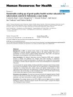
This
manual
follows
a
process
(see
Figure
1)
that
relates
reactor
plant
information
and
environmental
monitoring
data
to the
appropriate
protective
actions,
covering
the
entire
course
of
an
accident. Plant conditions
are
assessed
using
control
room
instrument
readings
and
other
observable
information
to
determine
the
risk
and
characteristics
of a
potential release.
Environmental
data
are
assessed
primarily
through
the use of
operational
intervention
levels
(OIL),
which
are
quantities
directly
measured
by the
field
instruments.
Default
OILs
have
been
calculated
in
advance
on the
basis
of the
characteristics
of
severe
reactor
accidents.
These
default
OILs
are
used
to
assess
environmental
data
and
take
protective
actions
until
sufficient
environmental
samples
are
taken
and
analysed
to
provide
a
basis
for
their
revision.
This
approach
allows
data
to be
quickly
evaluated,
and
decisions
on
protective actions
to be
promptly
made.
10
STRUCTURE
The
manual
is
organized
in
sections
based
on
proposed
assessment
organization
and in the
order
that
assessments
most
likely
will
be
performed.
Each
section
contains
methods,
that
are
stand-
alone
procedures.
Sections
start
with
an
overview,
containing
a
prioritized
summary
of
tasks
followed
by
procedures
which
provide
detailed
instructions.
There
are
four
ways
how to
find
the
appropriate
item
in the
manual
based
on:
(a)
accident assessment
process
by
using
Figure
1,
(b)
accident
assessment
organization
by
using
Figure
Ol,
(c)
contents
by
using
Table
of
Contents,
and
(d) key
words
using
Index
at the end of the
document.
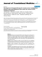
Assess
plant
conditions
SECTION
A
Project
protective
action
distances
SECTION
E
Assess
dose
rates
in
environment
SECTION
D
Assess
marker
isotopes
in
deposition
and
food
SECTION
D
Determine
public
protection
actions
and
emergency
worker
recommendation
SECTION
B
SECTION
C
Assess
total
isotopic
concentration
in
release,
deposition
and
food
SECTION
F
FIGURE
1
OVERVIEW
OF THE
ACCIDENT
ASSESSMENT PROCESS
NEXT
PAGE(S)
(•ft
BLANK
11
SECTION
O
ACCIDENT
ASSESSMENT
MANAGER
PROCEDURES
Caution:
The
procedures
in
this
section
must
be
revised
to
reflect
local
and
plant
conditions
for
which
they
will
be
applied
NEXT
PAGE(S)
left
BLANK
13
Performed
by:
Accident
Assessment
Manager
PROCEDURE
Ol
ACCIDENT
CONSEQUENCE
ASSESSMENT
MANAGEMENT
Pg.
Iof3
Purpose
To
establish
and
manage
the
organization
responsible
for
assessing
an
accident
to
develop
protective
action
recommendations
for the
public
and
radiation
protection
guidance
for
emergency
workers.
Discussion
Deterministic
health
effects
can be
prevented
by
taking
protective
actions
before
or
shortly
after
a
major
release.
This
is
accomplished
by
taking
immediate
actions
based
on
plant
conditions
and by
refining
these
initial
protective
actions
based
on
environmental
measurements.
The
risk
of
stochastic
health
effects
is
reduced
by
taking
actions
based
on
ambient
dose
rates
and
sample
analysis.
Sampling
and
analysis
are
performed
to
evaluate
the
safety
of the
food,
milk,
and
water
in
areas
where
ambient
dose
rates
or
deposition
levels
indicate
that
restriction
may be
warranted.
Sample
analysis
can
also
be
used
to
refine
the
operational
intervention
levels
(OILs)
used
in
protective
action
decision
making.
Input
I*-
Initial
event
briefings
Output
^
Recommended
actions
Step
1
Obtain
briefing
on the
plant
and
radiological
situation.
Step
2
Initiate
Priority
1
actions
in
Table
Ol
Step
3
Use
Worksheet
Ol for
assignment
of
personnel.
Step
4
Review
responsibilities
with
staff
as
outlined
in
Figure
Ol.
Ensure
assessments
are
performed
in
accordance
with
priorities
in
Table
Ol.
Hold
initial
and
periodic
briefings
to
discuss
assessment
priorities
and
individual
radiation
protection.
Step
5
Establish
communication
with
officials
responsible
for
off-site
implementation
of
protective
action
and
provide
continual
briefings
on
protective
actions
for the
public
and
emergency
workers
exposure
guidance.
Step
6
Ensure
that
personnel
are
relieved
at
least
every
12
hours.
15
Accident
Assessment
Procedure
Ol Pg. 2
of
3
Accident
Assessment
Manager
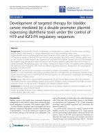
(a)
Section
O
Manage
assessment
of
accident
and
assure
off-site
officials
are
continually
bnefed
on
protective
actions
and
radiological
conditions
to
include
protection
for
workers
Nuclear
Condition
Assessment
Manager
(a)
Section
A
Classify
the
accident
and
determine
core
conditions,
release
route
and
release
conditions
Protective
Action
Manager
(a)
Section
B
Determine
public
protective
actions
based
on
classification
and
environmental
monitoring
Radiation
Protection
Manager
(a)
Section
C
Establish
exposure
guidance
for
facility
and
off-site
workers
and
assure
emergency
workers
are
briefed
on
their
guidance
and
doses
are
tracked
Environmental
Analyst
Section
D
Manage
environmental
1
monitoring
Projection
Analyst
Section
E
Project
distances
to
where
protective
actions
may be
needed
Sample
Analyst
Section
F
Based
on
sample
analysis
revise
the
default
OILs
and
evaluate
food
FIGURE
Ol
ACCIDENT
ASSESSMENT
ORGANIZATION
(a)
This
position
must
be
performed
on an
on-going
basis
by the
staff
in the
nuclear
power
plant
until
relieved.
[A
standalone
immediate
response
procedure
should
be
developed
for the
nuclear
power
plant
shift
supervisor.
This
procedure
will
direct
the
immediate
actions
to be
performed
by the
shift
supervisor
for
each
emergency
class].
16
TABLE
01
RESPONSE
PRIORITIES
Priority
1
2
3
4
5
6
Action
Classify
accident
based
on
plant
and
radiological
conditions
Notify
on-site
officials
and
off-
site
authorities
Activate
emergency
response
organization
Determine
and
recommend
public
protective
actions
Implement
emergency
worker
radiation
protection
guidance
Deploy
monitoring
teams
Assess
ambient
dose
rates
Project
off-site
consequences
Assess
air and
deposition
concentrations
Assess
food,
milk
and
water
contamination
Accident
Classification
Alert
•
•
•
Site
Area
Emergency
•
•
•
•
•
•
•
•
General
Emergency
•
•
•
•
•
•
•
•
•
•
•
When
On
an
on-going
basis
Complete
within
15
min.
after
classification
Complete
within
2
hours
after
classification
Immediately
after
classification
and
after
major
changes
in
plant
or
radiological
conditions
Complete
within
30
min.
after
classification
Initiate
within
30
min.
after
classification
On-site,
complete
within
30
min.
after
classification
Around
the
reactor
site,
complete
within
60
min.
after
classification
Beyond
vicinity
of
reactor
site,
initiate
within
4
hours
after
classification
Complete
within
2
hours
after
classification
Begin
within
4
hours
after
classification
Begin
within
24
hours
after
classification
Who
Nuclear
Condition
Assessment
Manager
(a)
Accident
Assessment
Manager
(a)
Accident
Assessment
Manager
(a)
Protective
Action
Manager
(a)
Radiation
Protection
Manager
(a)
Accident
Assessment
Manager
(a)
Environmental
Analyst
Projection
Analyst
Sample
Analyst
Environmental
Analyst
and
Sample
Analyst
mnOfM
(a)
These
tasks
must
be
performed
by
personnel
available
immediately
at the
site
on a 24
hour
basis
until
transfer
to
others.
SECTION
A
NUCLEAR
CONDITION
ASSESSMENT
MANAGER
PROCEDURES
Caution:
The
procedures
in
this
section
must
be
revised
to
reflect
local
and
plant
conditions
for
\vhich
they
will
be
applied.
NEXT
PAGE(S)
left
BLANK
19
Performed
by:
Nuclear
Condition
Assessment
Manager
PROCEDURE
AO
NUCLEAR
CONDITION ASSESSMENT
OVERVIEW
Pg.
1 ofl
Purpose
To
provide
overview
of
tasks
performed
by
Nuclear
Condition Assessment
Manager.
Discussion
Classification
of the
accident
is
most
important.
All
changes
in
plant
conditions
or
radiological
conditions
must
be
evaluated
immediately
to
determine
if the
classification
should
be
changed.
Report
an
increase
in
class
immediately
to the
Accident
Assessment
Manager
and
Protective
Action
Manager.
Step
1
Obtain
briefing
on the
situation
from
the
Accident
Assessment
Manager.
Follow
the
applicable
radiation
protection
instructions
provided
by the
Radiation
Protection
Manager.
Step
2
Classify
all
major
changes
in
plant
or
radiological
conditions
in
accordance
with
procedure
Al.
Immediately
report
core
damage
or
changes
in
classification
to the
Accident
Assessment
Manager.
Step
3
Evaluate
core
damage
state,
release
routes
and
conditions
using
procedures
A2 and A3.
Step
4
Ensure
Worksheet
Al is
updated
and
distributed
at
each
major
change
in
plant
or
radiological
conditions.
Step
5
Keep
recording
all
major
actions
and/or decisions
in a
logbook.
Step
6
At
the end of
your
shift
ensure
that
your
replacement
is
thoroughly
briefed.
21
Performed
by:
Nuclear
Condition
Assessment
Manager
PROCEDURE
Al
ACCIDENT
CLASSIFICATION
Pg.
1
of
24
Purpose
To
classify
abnormal
plant
and
radiological
conditions.
Discussion
Many
instruments
will
be
unreliable
during
an
accident.
Consequently,
never
use a
single
instrument
as the
basis
of a
classification.
Input
From
Control
room
i.
Reactor
systems
status
ii.
In
plant
radiological
conditions
iii.
Fuel
pool
status
iv.
Security
status
Ambient
dose
rate
around
the
plant
(Worksheet
Dl)
Output
^
Accident
class
Step
1
Classify
abnormal
plant
and
radiological
conditions
based
on the
following:
If the
reactor
is in:
Then
use:
Operating,
stand-by
or hot
shutdown
mode
Cold
shutdown
or
refueling
mode
Table
Al
Table
A2
Step
2
Record
the
class
on
Worksheet
Al
along
with
a
description
of the
accident
conditions.
Step
3
Reassess
the
classification
whenever
there
is a
major
change
in
plant
or
radiological
conditions
or
once
in an
hour.
Step
4
Report
any
change
in
class
immediately
to the
Accident
Assessment
Manager
and the
Protective
Action
Manager.
22
Nuclear
Condition Assessment
Procedure
Al Pg. 2
of
24
TABLE
Al
ACCIDENT
CLASSIFICATION
THE
OPERATING,
STAND-BY
OR HOT
SHUTDOWN
MODE
Read
me
first
The
table
must
be
reviewed
and
revised
to
match
site
specifics
and
where
possible
the
emergency
action
levels
(EAL)
should
be
replaced
with
a
specific
plant
instrument
readings,
equipment
status
or
other
observable.
The
three
possible
levels
of
emergency
are
defined
as:
General Emergency:
Events
resulting
in an
actual
or
substantial
risk
of a
release
requiring
implementation
of
urgent
protective
actions
off-site.
This
includes:
1)
actual
or
projected
damage
to the
core
or
large
amounts
of
spent
fuel
or 2)
releases
off-site
resulting
in a
dose exceeding
the
urgent
protective
actions
interventions
levels.
Urgent
protective
actions
are
recommended
immediately
for the
public
near
the
plant when
this
level
of
emergency
is
declared.
Site
Area
Emergency:
Events
resulting
in a
major
decrease
in the
level
of
protection
for the
public
or
on-site
personnel.
This
includes:
1) a
major
decrease
in the
level
of
protection
provided
to the
core
or
large
amounts
of
spent
fuel,
2)
conditions
where
any
additional failures
could
result
in
damage
to
core
or
spent
fuel
or 3)
high
doses
on-site
or
doses
off-site
approaching
the
urgent
protective actions interventions
levels.
At
this
class
actions
should
be
taken
to
control
the
dose
to
on-site
personnel
and
preparations
should
be
made
to
take
protective
actions
off-site.
Alert:
Events
involving
an
unknown
or
significant
decrease
in the
level
of
protection
for the
public
or
on-site
personnel.
At
this
class
the
state
of
readiness
of the on and
off-site
response
organizations
is
increased
and
additional
assessments
are
made.
How
to use the
table:
Review
all the
accident
entry
conditions
in
column
1. For
each
entry
condition
that
applies,
select
the
class
by
matching
the EAL
criteria
to the
left.
Classify
the
accident
at the
highest
level
indicated:
Highest
-
General Emergency,
Lowest
-
Alert.
23
TABLE
Al
ACCIDENT
CLASSIFICATION
THE
OPERATING,
STAND-BY
OR HOT
SHUTDOWN
MODE
For the
following
accident
entry
conditions;
Declare
a
General
Emergency
if:
Declare
a
Site
Area
Emergency
if:
Declare
an
Alert
if:
CRITICAL
SAFETY
FUNCTION
IMPAIRMENT
Failure
to
scram
(stop
nuclear
reaction)
Inadequate
primary
system
decay
heat
removal
Failure
to
scram
when
above
5%
power
and any of the
following:
••
PWR
negative
cooling
margin
by
Figure
A 1
or
>
vessel
water
level
below
top of
active
fuel,
or
»
major
(100
-
lOOOx)
increase
in
multiple
radiation
monitors
or
*•
other
indication
of
actual
or
imminent
core
damage
Failure
to
scram
when
above
5%
power
and
abnormal
conditions
indicate
automatic
or
manual
scram
is
necessary
Actual
or
protected
long
term
failure
of the
ability
to
remove
decay
heat
to the
environment
potentially
affecting
the
ability
to
protect
the
core
Failure
to
fully
shutdown
as
part
of
normal
shutdown
and
there
is
sufficient
heat
removal
available
(ultimate
heat
sink
available
and
sufficient)
TABLE
Al
ACCIDENT
CLASSIFICATION
THE
OPERATING,
STAND-BY
OR HOT
SHUTDOWN
MODE
For the
following
accident
entry
conditions:
Declare
a
General
Emergency
if:
Declare
a
Site
Area
Emergency
if:
Declare
an
Alert
if:
PWR
abnormal primary
system
temperature
(Inadequate
core
cooling)
Note: Temperature
should
be
measures
in the
vessel.
Most
PWRs
have
core
exit
thermocouples
(CET)
to
measure
temperatures
in the
vessel.
Use the
average
of
the
highest
four
CET
readings.
If
there
is
water
flow
the
hot
leg
temperature
(T^
could
also
be
used
ifCETs
are not
available.
CETs
are not
accurate
after
core
damage.
For
BWR
there
are no
instruments
that
provide
a
valid
reading
of
core
temperature.
PWR
-
Negative
cooling
margin
by
Figure
Al or
primary
system
temperature
exceeds
scale
for
greater
than
15
minutes
[or
insert
site
specific
time
for
core
damage
following
a
loss
of
coolant
accident]
and any of the
following:
>
vessel
injection
rate
less than
Figure
A2
[plant
specific
pump
capacity
vs
pressure]
or
*•
vessel
water
level
below
top of
active
fuel
or
>
major
(100
-1
OOOx)
increases
in
multiple
radiation
monitors
or
»
other
indications
of
actual
or
imminent
core
damage
PWR
-
Negative
cooling
margin
by
Figure
Al for
greater
than
15
minutes
[or
insert
site
specific
time
that
core
damage
is
possible
following
a
loss
of
coolant
accident]
PWR
primary
system
pressure
and
temperature
indicate
negative
cooling
margin
by
Figure
A1 for
greater
than
5
minutes.
Primary
system
temperature greater
than
750
°C
to
TABLE
Al
ACCIDENT
CLASSIFICATION
THE
OPERATING,
STAND-BY
OR HOT
SHUTDOWN
MODE
For the
following
accident
entry
conditions;
Declare
a
General
Emergency
if:
Declare
a
Site
Area
Emergency
if:
Declare
an
Alert
if:
Abnormal
vessel
water
level
(Inadequate
core
cooling)
Notes:
-
PWR
pressurizer
levels
may not
be
valid
indicators
of
vessel
water
level
under
accident
conditions
- PWR
water
levels
measured
in
the
vessel
can
have
considerable
uncertainties
(30%)
and
should
only
be
used
for
trends
assessment.
- BWR
high
drywell
temperature
and low
pressure
accidents
(e.g.
LOCAs)
can
cause
the
water
level
to
read
erroneously
high.
-
Both
PWR and BWR
water
level
readings
are
unreliable
after
core
damage.
Vessel
water
level
is, or
projected
to be,
below
top of
active
fuel
for
greater
than
15
minutes.
Vessel
water
is or is
projected
to be
below
top of
active
fuel.
Vessel
water
level
decreasing
over
a
longer
time
period
than
expected
if
systems
are
responding
as
designed.
Vessel
water
level
is or
projected
to be
below
top of
active
fuel
and any of the
following:
••
vessel
injection
rate
less
than
Figure
A2
[plant
specific
pump
capacity
vs
pressure]
or
*•
major
(100
-
lOOOx)
increases
in
multiple
radiation
monitors
or
»•
other
indications
of
imminent
or
_____actual
core
damage______
TABLE
Al
ACCIDENT CLASSIFICATION
THE
OPERATING, STAND-BY
OR HOT
SHUTDOWN
MODE
For the
following
accident
entry
conditions:
Declare
a
General
Emergency
if:
Declare
a
Site
Area
Emergency
if:
Declare
an
Alert
if:
Loss
of AC or DC
power
sources
Actual
or
projected
loss
of all AC or DC
power
needed
for
safety
systems
operation
likely
for
greater
than
45
minutes
[or
insert
site
specific
time required
to
uncover
core
for
more
than
15
minutes]__________
Actual
or
projected
loss
of AC or DC
power
needed
for
safety
systems
operation
for
greater
than
30
minutes
[or
insert
site
specific
time
required
to
uncover
the
core]
AC or DC
power
needed
for
safety
systems
operation
is
lost
or
reduced
to a
single
source
Loss
of all AC or DC
power
needed
for
safety
systems
operation
and any of the
following:
*•
vessel
water
level
below
top of
active
fuel,
or
>
major
(100
-1
OOOx)
increase
in
multiple
radiation
monitors
or
*•
other
indication
of
actual
or
imminent
core
damage
Puzzling
conditions
affecting
safety
systems
Conditions
which
are not
understood
and
which
could
potentially
affect
safety
systems._________________
ro
to
do
TABLE
Al
ACCIDENT
CLASSIFICATION
THE
OPERATING,
STAND-BY
OR HOT
SHUTDOWN
MODE
For the
following
accident
entry
conditions:
Loss
or
degraded
control
of
safety
systems.
Declare
a
General
Emergency
if:
Unavailability
or
unreliable
functioning
of
safety
system
instruments
or
controls
in the
control
room
and
remote
control
locations
and any of the
following:
••
vessel
water
level
below
the top of
active
fuel
or
••
major
( 1 00 - 1
OOOx)
increases
in
multiple
radiation
monitors
or
»
other
indications
of
imminent
or
actual
core
damage
Declare
a
Site
Area
Emergency
if:
Unavailability
or
unreliable
functioning
of
safety
system
instruments
or
controls
in the
control
room
for
more
than
1 5
minutes
and
major
transient
in
progress
potentially
affecting
the
ability
to
protect
the
core.
Declare
an
Alert
if:
Unavailability
or
unreliable
functioning
of
safety
system
instruments
or
controls
in
the
control
room
for
more
than
15
minutes.
LOSS
OF
FISSION
PRODUCT
BARRIERS
Major
increased
risk
of
damage
to
the
core
or
spent
fuel
Note:
Core
damage
can
occur
if
the
core
is
uncovered
for
more
than
15
minutes.
Confirmed
core
damage
Loss
of
all
the
systems
required
to
protect
the
core
or
spent
fuel
for
more
than
45
minutes
[or
insert
site
specific
time
required
to
uncover
core
for
more
than
15
minutes]
[insert
site
specific
readings
such
as PWR
failed
fuel
monitor
or BWR
off-gas
monitor
indicating
release
of
20%
of
gap
inventory]
Failure
of an
additional
safety
system
component
will
result
in
uncovery
of the
core
or
spent
fuel
(Loss
of
redundancy
in
safety
systems)
[insert
site
specific
readings
such
as PWR
failed
fuel
monitor
or BWR
off-gas
monitor
indicating
1%
release
of
gap
inventory
]
Actual
or
predicted
failures
which
increase
the
risk
of
core
damage,
spent
fuel
damage
or of a
major
release
TABLE
Al
ACCIDENT
CLASSIFICATION
THE
OPERATING,
STAND-BY
OR HOT
SHUTDOWN
MODE
For the
following
accident
entry
conditions;
Declare
a
General
Emergency
if:
Declare
a
Site
Area
Emergency
if:
Declare
an
Alert
if:
High
primary
coolant
1-131
concentration
Note:
Coolant
samples
should
not be
taken
if
they
will
result
in
high
individual
doses.
-Use
only
concentrations
from
sample
taken
after
the
start
of
the
event.
-Coolant
concentrations
may not
be
representative
-
Assumes
the
core
may be
uncoolable
after
10%
melt.____
1-131
concentration
is
greater
than.,
[insert
site
specific
values
for
release
of 10% of
core
inventory]
1-131
concentration
is
greater
than
[insert
site
specific
value
indicating
release
of
20%
of
the gap
inventory]
1-131
concentration
greater
than
[insert
site
specific
value
100
times
technical
specifications
or
other
operational
limits]
Primary
system
leak.
Primary
system
leak
and all
normal
and
emergency
core
coolant
systems
(ECCS)
operational
and any of the
following:
»•
injection
into
the
vessel
less
than
the
amount
shown
in
Figure
A2
or
*•
vessel
water
level
below
top of
active
fuel
and
decreasing
or
»•
major
(100
-
lOOOx)
increases
in
multiple
radiation
monitors
or
*
other
indications
of
imminent
or
_____actual
core
damage_______
Primary
system
leak
for
more
than
15
minutes
requiring
all
normal
and
high
pressure
emergency
core
coolant
systems
to
maintain
primary
system
water
level
[insert
site
specific
indicators]
Primary
system
leak
rate
for
more
than
15
minutes
requiring
at
least
continuous
operation
of all
normal
charging
pumps
to
maintain
primary
system
water
level
[insert
site
specific
indicators]