Lý thuyết diode
Bạn đang xem bản rút gọn của tài liệu. Xem và tải ngay bản đầy đủ của tài liệu tại đây (1.1 MB, 97 trang )
Lý thuyết diode
Từ Vựng (1)
•
anode
•
bulk resistance = điện trở khối
•
cathode
•
diode
•
ideal diode = diode lý tưởng
•
knee voltage = điện áp gối
•
linear device = dụng cụ tuyến tính
•
load line = đường tải
Từ Vựng (2)
•
maximum forward current = dòng
thuận cực đại
•
nonlinear device = dụng cụ phi tuyến
•
Ohmic resistance = điện trở Ohm
•
power rating = định mức công suất
•
up-down analysis = phân tích tăng-
giảm
Nội dung chương 3
3-1 Các ý tưởng cơ bản
3-2 Diode lý tưởng
3-3 Xấp xỉ bậc 2
3-4 Xấp xỉ bậc 3
3-5 Trounleshooting
3-6 Phân tích mạch tăng-giảm
3-7 Đọc bảng dữ liệu
3-8 Cách tính điện trở khối
3-9 Điện trở DC của diode
3-10 Đường tải
3-11 Diode dán bề mặt
Properties of Diodes
Properties of Diodes
Kristin Ackerson, Virginia Tech EE
Kristin Ackerson, Virginia Tech EE
Spring 2002
Spring 2002
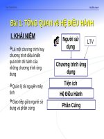
Figure 1.10 – The Diode Transconductance Curve
Figure 1.10 – The Diode Transconductance Curve
2
2
•
V
V
D
D
= Bias Voltage
= Bias Voltage
•
I
I
D
D
= Current through
= Current through
Diode. I
Diode. I
D
D
is Negative
is Negative
for Reverse Bias and
for Reverse Bias and
Positive for Forward
Positive for Forward
Bias
Bias
•
I
I
S
S
= Saturation
= Saturation
Current
Current
•
V
V
BR
BR
= Breakdown
= Breakdown
Voltage
Voltage
•
V
V
φ
φ
= Barrier Potential
= Barrier Potential
Voltage
Voltage
V
V
D
D
I
I
D
D
(mA)
(mA)
(nA)
(nA)
V
V
BR
BR
~V
~V
φ
φ
I
I
S
S
Properties of Diodes
Properties of Diodes
The Shockley Equation
The Shockley Equation
Kristin Ackerson, Virginia Tech EE
Kristin Ackerson, Virginia Tech EE
Spring 2002
Spring 2002
•
The transconductance curve on the previous slide is characterized by
The transconductance curve on the previous slide is characterized by
the following equation:
the following equation:
I
I
D
D
= I
= I
S
S
(e
(e
V
V
D
D
/
/
η
η
V
V
T
T
– 1)
– 1)
•
As described in the last slide, I
As described in the last slide, I
D
D
is the current through the diode, I
is the current through the diode, I
S
S
is
is
the saturation current and V
the saturation current and V
D
D
is the applied biasing voltage.
is the applied biasing voltage.
•
V
V
T
T
is the thermal equivalent voltage and is approximately 26 mV at room
is the thermal equivalent voltage and is approximately 26 mV at room
temperature. The equation to find V
temperature. The equation to find V
T
T
at various temperatures is:
at various temperatures is:
V
V
T
T
=
=
kT
kT
q
q
k = 1.38 x 10
k = 1.38 x 10
-23
-23
J/K T = temperature in Kelvin q = 1.6 x 10
J/K T = temperature in Kelvin q = 1.6 x 10
-19
-19
C
C
∀
η
η
is the emission coefficient for the diode. It is determined by the way
is the emission coefficient for the diode. It is determined by the way
the diode is constructed. It somewhat varies with diode current. For a
the diode is constructed. It somewhat varies with diode current. For a
silicon diode
silicon diode
η
η
is around 2 for low currents and goes down to about 1
is around 2 for low currents and goes down to about 1
at higher currents
at higher currents
Diode Circuit Models
Diode Circuit Models
Kristin Ackerson, Virginia Tech EE
Kristin Ackerson, Virginia Tech EE
Spring 2002
Spring 2002
The Ideal Diode
The Ideal Diode
Model
Model
The diode is designed to allow current to flow in
The diode is designed to allow current to flow in
only one direction. The perfect diode would be a
only one direction. The perfect diode would be a
perfect conductor in one direction (forward bias)
perfect conductor in one direction (forward bias)
and a perfect insulator in the other direction
and a perfect insulator in the other direction
(reverse bias). In many situations, using the ideal
(reverse bias). In many situations, using the ideal
diode approximation is acceptable.
diode approximation is acceptable.
Example: Assume the diode in the circuit below is ideal. Determine the
Example: Assume the diode in the circuit below is ideal. Determine the
value of I
value of I
D
D
if a) V
if a) V
A
A
= 5 volts (forward bias) and b) V
= 5 volts (forward bias) and b) V
A
A
= -5 volts (reverse
= -5 volts (reverse
bias)
bias)
+
+
_
_
V
V
A
A
I
I
D
D
R
R
S
S
= 50
= 50
Ω
Ω
a) With V
a) With V
A
A
> 0 the diode is in forward bias
> 0 the diode is in forward bias
and is acting like a perfect conductor so:
and is acting like a perfect conductor so:
I
I
D
D
= V
= V
A
A
/R
/R
S
S
= 5 V / 50
= 5 V / 50
Ω
Ω
= 100 mA
= 100 mA
b) With V
b) With V
A
A
< 0 the diode is in reverse bias
< 0 the diode is in reverse bias
and is acting like a perfect insulator,
and is acting like a perfect insulator,
therefore no current can flow and I
therefore no current can flow and I
D
D
= 0.
= 0.
Diode Circuit Models
Diode Circuit Models
Kristin Ackerson, Virginia Tech EE
Kristin Ackerson, Virginia Tech EE
Spring 2002
Spring 2002
The Ideal Diode with
The Ideal Diode with
Barrier Potential
Barrier Potential
This model is more accurate than the simple
This model is more accurate than the simple
ideal diode model because it includes the
ideal diode model because it includes the
approximate barrier potential voltage.
approximate barrier potential voltage.
Remember the barrier potential voltage is the
Remember the barrier potential voltage is the
voltage at which appreciable current starts to
voltage at which appreciable current starts to
flow.
flow.
Example: To be more accurate than just using the ideal diode model
Example: To be more accurate than just using the ideal diode model
include the barrier potential. Assume V
include the barrier potential. Assume V
φ
φ
= 0.3 volts (typical for a
= 0.3 volts (typical for a
germanium diode) Determine the value of I
germanium diode) Determine the value of I
D
D
if V
if V
A
A
= 5 volts (forward bias).
= 5 volts (forward bias).
+
+
_
_
V
V
A
A
I
I
D
D
R
R
S
S
= 50
= 50
Ω
Ω
With V
With V
A
A
> 0 the diode is in forward bias
> 0 the diode is in forward bias
and is acting like a perfect conductor
and is acting like a perfect conductor
so write a KVL equation to find I
so write a KVL equation to find I
D
D
:
:
0 = V
0 = V
A
A
– I
– I
D
D
R
R
S
S
- V
- V
φ
φ
I
I
D
D
= V
= V
A
A
- V
- V
φ
φ
= 4.7 V = 94 mA
= 4.7 V = 94 mA
R
R
S
S
50
50
Ω
Ω
V
V
φ
φ
+
+
V
V
φ
φ
+
+
Diode Circuit Models
Diode Circuit Models
The Ideal Diode
The Ideal Diode
with Barrier
with Barrier
Potential and
Potential and
Linear Forward
Linear Forward
Resistance
Resistance
This model is the most accurate of the three. It includes a
This model is the most accurate of the three. It includes a
linear forward resistance that is calculated from the slope of
linear forward resistance that is calculated from the slope of
the linear portion of the transconductance curve. However,
the linear portion of the transconductance curve. However,
this is usually not necessary since the R
this is usually not necessary since the R
F
F
(forward
(forward
resistance) value is pretty constant. For low-power
resistance) value is pretty constant. For low-power
germanium and silicon diodes the R
germanium and silicon diodes the R
F
F
value is usually in the
value is usually in the
2 to 5 ohms range, while higher power diodes have a R
2 to 5 ohms range, while higher power diodes have a R
F
F
value closer to 1 ohm.
value closer to 1 ohm.
Linear Portion of
Linear Portion of
transconductance
transconductance
curve
curve
V
V
D
D
I
I
D
D
V
V
D
D
I
I
D
D
R
R
F
F
=
=
V
V
D
D
I
I
D
D
Kristin Ackerson, Virginia Tech EE
Kristin Ackerson, Virginia Tech EE
Spring 2002
Spring 2002
+
+
V
V
φ
φ
R
R
F
F
Diode Circuit Models
Diode Circuit Models
The Ideal Diode
The Ideal Diode
with Barrier
with Barrier
Potential and
Potential and
Linear Forward
Linear Forward
Resistance
Resistance
Kristin Ackerson, Virginia Tech EE
Kristin Ackerson, Virginia Tech EE
Spring 2002
Spring 2002
Example: Assume the diode is a low-power diode
Example: Assume the diode is a low-power diode
with a forward resistance value of 5 ohms. The
with a forward resistance value of 5 ohms. The
barrier potential voltage is still: V
barrier potential voltage is still: V
φ
φ
= 0.3 volts
= 0.3 volts
(typical for a germanium diode) Determine the value
(typical for a germanium diode) Determine the value
of I
of I
D
D
if V
if V
A
A
= 5 volts.
= 5 volts.
+
+
_
_
V
V
A
A
I
I
D
D
R
R
S
S
= 50
= 50
Ω
Ω
V
V
φ
φ
+
+
R
R
F
F
Once again, write a KVL equation
Once again, write a KVL equation
for the circuit:
for the circuit:
0 = V
0 = V
A
A
– I
– I
D
D
R
R
S
S
-
-
V
V
φ
φ
- I
- I
D
D
R
R
F
F
I
I
D
D
= V
= V
A
A
- V
- V
φ
φ
= 5 – 0.3 = 85.5 mA
= 5 – 0.3 = 85.5 mA
R
R
S
S
+ R
+ R
F
F
50 + 5
50 + 5
Diode Circuit Models
Diode Circuit Models
Kristin Ackerson, Virginia Tech EE
Kristin Ackerson, Virginia Tech EE
Spring 2002
Spring 2002
Values of ID for the Three Different Diode Circuit Models
Values of ID for the Three Different Diode Circuit Models
Ideal Diode
Model
Ideal Diode
Model with
Barrier
Potential
Voltage
Ideal Diode
Model with
Barrier
Potential and
Linear Forward
Resistance
I
D
100 mA 94 mA 85.5 mA
These are the values found in the examples on previous
These are the values found in the examples on previous
slides where the applied voltage was 5 volts, the barrier
slides where the applied voltage was 5 volts, the barrier
potential was 0.3 volts and the linear forward resistance
potential was 0.3 volts and the linear forward resistance
value was assumed to be 5 ohms.
value was assumed to be 5 ohms.
The Q Point
The Q Point
Kristin Ackerson, Virginia Tech EE
Kristin Ackerson, Virginia Tech EE
Spring 2002
Spring 2002
The operating point or Q point of the diode is the quiescent or no-
The operating point or Q point of the diode is the quiescent or no-
signal condition. The Q point is obtained graphically and is really only
signal condition. The Q point is obtained graphically and is really only
needed when the applied voltage is very close to the diode’s barrier
needed when the applied voltage is very close to the diode’s barrier
potential voltage. The example
potential voltage. The example
3
3
below that is continued on the next
below that is continued on the next
slide, shows how the Q point is determined using the
slide, shows how the Q point is determined using the
transconductance curve and the load line.
transconductance curve and the load line.
+
+
_
_
V
V
A
A
= 6V
= 6V
I
I
D
D
R
R
S
S
= 1000
= 1000
Ω
Ω
V
V
φ
φ
+
+
First the load line is found by substituting in
First the load line is found by substituting in
different values of V
different values of V
φ
φ
into the equation for I
into the equation for I
D
D
using
using
the ideal diode with barrier potential model for the
the ideal diode with barrier potential model for the
diode. With R
diode. With R
S
S
at 1000 ohms the value of R
at 1000 ohms the value of R
F
F
wouldn’t have much impact on the results.
wouldn’t have much impact on the results.
I
I
D
D
= V
= V
A
A
– V
– V
φ
φ
R
R
S
S
Using V
Using V
φ
φ
values of 0 volts and 1.4 volts we obtain
values of 0 volts and 1.4 volts we obtain
I
I
D
D
values of 6 mA and 4.6 mA respectively. Next
values of 6 mA and 4.6 mA respectively. Next
we will draw the line connecting these two points
we will draw the line connecting these two points
on the graph with the transconductance curve.
on the graph with the transconductance curve.
This line is the load line.
This line is the load line.
The Q Point
The Q Point
I
I
D
D
(mA)
(mA)
V
V
D
D
(Volts)
(Volts)
2
2
4
4
6
6
8
8
10
10
12
12
0.2
0.2
0.4
0.4
0.6
0.6
0.8
0.8
1.0
1.0
1.2
1.2
1.4
1.4
The
The
transconductance
transconductance
curve below is for a
curve below is for a
Silicon diode. The
Silicon diode. The
Q point in this
Q point in this
example is located
example is located
at 0.7 V and 5.3 mA.
at 0.7 V and 5.3 mA.
4.6
4.6
Kristin Ackerson, Virginia Tech EE
Kristin Ackerson, Virginia Tech EE
Spring 2002
Spring 2002
0.7
0.7
5.3
5.3
Q Point:
Q Point:
The intersection of the
The intersection of the
load line and the
load line and the
transconductance curve.
transconductance curve.
Dynamic Resistance
Dynamic Resistance
Kristin Ackerson, Virginia Tech EE
Kristin Ackerson, Virginia Tech EE
Spring 2002
Spring 2002
The dynamic resistance of the diode is mathematically
The dynamic resistance of the diode is mathematically
determined as the inverse of the slope of the transconductance
determined as the inverse of the slope of the transconductance
curve. Therefore, the equation for dynamic resistance is:
curve. Therefore, the equation for dynamic resistance is:
r
r
F
F
=
=
η
η
V
V
T
T
I
I
D
D
The dynamic resistance is used in determining the voltage drop
The dynamic resistance is used in determining the voltage drop
across the diode in the situation where a voltage source is
across the diode in the situation where a voltage source is
supplying a sinusoidal signal with a dc offset.
supplying a sinusoidal signal with a dc offset.
The ac component of the diode voltage is found using the
The ac component of the diode voltage is found using the
following equation:
following equation:
v
v
F
F
= v
= v
ac
ac
r
r
F
F
r
r
F
F
+ R
+ R
S
S
The voltage drop through the diode is a combination of the ac and
The voltage drop through the diode is a combination of the ac and
dc components and is equal to:
dc components and is equal to:
V
V
D
D
= V
= V
φ
φ
+ v
+ v
F
F
Dynamic Resistance
Dynamic Resistance
Kristin Ackerson, Virginia Tech EE
Kristin Ackerson, Virginia Tech EE
Spring 2002
Spring 2002
Example:
Example:
Use the same circuit used for the Q point example but
Use the same circuit used for the Q point example but
change the voltage source so it is an ac source with a dc offset. The
change the voltage source so it is an ac source with a dc offset. The
source voltage is now, v
source voltage is now, v
in
in
= 6 + sin(wt) Volts. It is a silicon diode so the
= 6 + sin(wt) Volts. It is a silicon diode so the
barrier potential voltage is still 0.7 volts.
barrier potential voltage is still 0.7 volts.
+
+
v
v
in
in
I
I
D
D
R
R
S
S
= 1000
= 1000
Ω
Ω
V
V
φ
φ
+
+
The DC component of the circuit is the
The DC component of the circuit is the
same as the previous example and
same as the previous example and
therefore I
therefore I
D
D
=
=
6V – 0.7 V
6V – 0.7 V
= 5.3 mA
= 5.3 mA
1000
1000
r
r
F
F
=
=
η
η
V
V
T
T
=
=
1 * 26 mV
1 * 26 mV
= 4.9
= 4.9
I
I
D
D
5.3 mA
5.3 mA
η
η
= 1 is a good approximation if the dc
= 1 is a good approximation if the dc
current is greater than 1 mA as it is in
current is greater than 1 mA as it is in
this example.
this example.
v
v
F
F
= v
= v
ac
ac
r
r
F
F
= sin(wt) V 4.9
= sin(wt) V 4.9
= 4.88 sin(wt) mV
= 4.88 sin(wt) mV
r
r
F
F
+ R
+ R
S
S
4.9
4.9
+ 1000
+ 1000
Therefore, V
Therefore, V
D
D
= 700 + 4.9 sin (wt) mV (the voltage drop across the
= 700 + 4.9 sin (wt) mV (the voltage drop across the
diode)
diode)
Chương 4
Các mạch diode
Từ Vựng (1)
•
Bias = phân cực
•
Capacitor-input filter = Mạch lọc ngõ vào
(dùng) tụ
•
Choke-input filter = Mạch lọc ngõ vào
(dùng) cuộn dây
•
Clamper = mạch kẹp
•
Clipper = mạch xén
•
dc value of signal = giá trị DC của tín hiệu
•
Filter = mạch lọc, bộ lọc
•
Half-wave signal = tín hiệu bán kỳ
Từ Vựng (2)
•
IC voltage regulator = Mạch ổn áp IC
•
Integrated circuit = IC = vi mạch =
mạch tích hợp
•
Passive filter = mạch lọc thụ động
•
Peak detector = mạch tách sóng đỉnh
•
Peak inverse voltage = điện áp
ngược đỉnh
•
Polarized capacitor = tụ (điện) hóa
(học) = tụ có phân cực
•
Power supply = nguồn cấp điện
Từ Vựng (3)
•
Rectifier = mạch/bộ chỉnh lưu
•
Ripple = gợn
•
Surge current = dòng điện quá độ
•
Surge resistor = điện trở bảo vệ quá độ
•
Unidirectional local current = dòng
điện cục bộ đơn hướng
•
Volatge multiplier = mạch nhân điện áp
•
Waveform = dạng sóng
Nội dung chương 4
4-1 Mạch chỉnh lưu bán kỳ
4-2 Máy biến thế
4-3 Mạch chỉnh lưu toàn sóng
4-4 Mạch chỉnh lưu cầu
4-5 Mạch lọc ngõ vào (dùng) cuộn dây
4-6 Mạch lọc ngõ vào (dùng) tụ
4-7 Điện áp ngược đỉnh và dòng quá độ
4-8 Một số vấn đề khác về nguồn cấp điện
4-9 Troubleshooting
4-10 Mạch xén và mạch hạn biên (limiter)
4-11 Mạch kẹp
4-12 Mạch nhân điện áp
4-1 Mạch chỉnh lưu bán kỳ
H. 4-1 (a) Mạch chỉnh lưu bán kỳ lý tưởng;
(b) bán kỳ dương (diode ON); (c) bán kỳ âm (diode OFF)
4-1 Mạch chỉnh lưu bán kỳ (tt)
Các dạng sóng lý tưởng
Hình 4-2
4-1 Mạch chỉnh lưu bán kỳ (tt)
•
Điện áp ra đỉnh bằng điện áp vào đỉnh:
•
Giá trị DC của tín hiệu bán kỳ V
dc
:
•
Tần số ra:
f
out
= f
in
•
Xấp xỉ bậc 2:
V
p(out)
= V
p(in)
– 0.7V (diode Si)
A simple Battery charger-Example of
a Rectifier
•
Can be used to charge a car battery from the alternator
4-2 Máy biến thế (Transformer)
•
Máy biến thế là 1 cặp cuộn dây có
ghép hỗ cảm với nhau (để truyền
năng lượng từ cuộn này sang cuộn
kia bằng từ trường biến thiên).
•
Với số vòng dây khác nhau ta có
máy biến thế tăng áp (step up) hay
giảm áp (step down).