hệ thống lái của xe ô tô hyundai aero sp
Bạn đang xem bản rút gọn của tài liệu. Xem và tải ngay bản đầy đủ của tài liệu tại đây (870.9 KB, 45 trang )
STEERING
SYSTEM
GENERAL ST - 2
SPECIFICATION ST - 6
SERVICE STANDARDS ST - 7
TIGHTENING TORQUE ST - 8
TROUBLESHOOTING ST - 9
SERVICE PROCEDURE ST-14
INTEGRAL POWER STEERING GEAR ST-27
POWER STEERING OIL PUMP ST-37
POWER STEERING OIL TANK ST-43
ST-2 STEERING SYSTEM
GENERAL
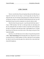
The steering system allows the driver to freely change the traveling direction of the vehicle. The steering force of the
steering wheel is transmitted through the steering shaft, power steering gear, pitman arm and drag link to the knuckle arm
to steer the vehicle.
The system has an integral type power steering gear installed in the gear box to reduce the steering effort.
The power steering system hydraulic pressure circuits are as shown below.
ECYST01A
Oil Tank
Oil Pump Power Steering Gear
Piping
Knuckle arm
Power steering
oil pump
Pitman arm
Power steering
oil reservoir tank
Slave lever
Power steering gear
1st drag link
2nd drag
link
ST-3
ECYST02A
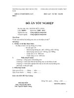
Steering Linkage
Drag Link Assembly
Leaf suspension type : The drag link transmits the force of power
steering gear pitman arm to slove lever and knucle arm.
Steering Wheel and Shaft
The steering shaft is a tlelscopic and tilt type which can by adjusing
lock lever select the best driving position by adjusting lock lever.
Lock lever
Free
Lock
Telescopic
Tilt
MA560040
Tie Rod Assembly
1. Leaf suspension type : It connects the laft and right tie-rod arm
2. The connecting point of tie arod and tie rod end is tightened by
a left hard bolt at left and a right hand bolt at right.
Slave Lever (Leaf-suspension only)
The slave lever connects the 1st drag link and 2nd drag by multi-
plying the force from 1st drag link to 2nd drag link.
Ball joint
Spring
MA560050
Ball joint
Tie rod
Tie rod end
MA560060
Slave lever
1st drag link
2nd drag link
GENERAL
ST-4 STEERING SYSTEM
Right Turn
When the steering wheel is turned clockwise, the load from the tires acts on the worm shaft to twist the torsion bar. As a
result, the rotor turns clockwise with respect to the worm shaft, decreasing the axial direction groove clearance. This limits
flow of the hydraulic oil to the oil tank and now the hydraulic oil from thr oil pump enters the cylinder chamber A to cause the
piston to move to the cylinder chamber B.
The hydraulic oil in the cylinder chamber moves, the torsion bar that has been twisted returns to the neutral position. The
force that has caused twisted returns to the neutral position. The force that has caused twisting of the torsion bar during
steering is transmitted to the steering wheel as a steering reaction force which gives the driver a sence of steering response.
A left turn is also made on the same operating principles as the right turn but in opposite direction.
Integral Power Steering Gear
This device consisting of the power cylinder section (output section) that also serves as the steering gear and the control
valve section (control section) reduces the power required to operate the steering wheel.
Straight Ahead Driving
When there is no steering torque from the steering wheel, no relative displacement is caused between the stub shaft and
th worm shaft and hence the rotor (or spool) is at the neutral position on the worm shaft (or sleeve). Accordingly, the
hydraulic oil supplied by the oil pump is allowed to flow through the worm shaft groove back to the oil tank.
Namely, no pressure diffference develops between cylinder chambers A and B so that the piston (ball nut) remains
stationay at the neutral position.
CYST001C / CYST001D
CYST001E/ CYST001F
Cylinder chamber B
Worm shaft
Stub shaft
Piston
Rotor
Cylinder chamber A
Torison bar
To cylinder
chamber B
To cylinder
chamber A
Worm shaft
To oil tank
To oil tank
To cylinder
chamber B
To cylinder
chamber A
To oil tank
From oil pump
From oil pump
To cylinder
chamber B
From oil pump
To cylinder
chamber A
To cylinder
chamber B
From oil pump
To cylinder
chamber A
To oil tank
To cylinder
chamber A
Worm shaft
To oil tank
To cylinder
chamber B
To cylinder
chamber A
To oil tank
From oil pump
From oil pump
From cylinder
chamber B
Rotor
Rotor
Cylinder chamber A
Stub shaft
Piston
Worm shaft
Cylinder chamber B
Torison bar
ST-5
MA560110
MA560120
Delivery stroke
Suction stroke
Delivery stroke
Metering orifice
(develops pressure
difference P
P=P1-P2
Rotor turning
direction
Manual Steering
Even if the hydraulic pressure ceases to act on the power steering
booster due to a stalled engine, defective oil pump, oil leaks or
other causes, the mechanical power is directly transmitted from
the stub shaft to the worm shaft by the stopper mechanism pro-
vided between the stub shaft and worm, allowing manual steering.
Power Steering Oil Pump
The vanes mounted to the rotor move in and out along the inside
surface of the cam ring to cause suction and discharge of the hy-
draulic oil.
1. Flow Control Valve
This valve causes excess amount of oil to flowback to the oil
tank to keep a constant flow of oil to the power steering booster.
JMS56-011
Suction stroke
Cam ring
Vane
Rotor
Chamber A
Pump
scution port
Flow control spring
Spool
Chamber B
To power
steering
booster
Warm shaft
Stub shaft
Torsion bar
MA560130
Chamber A
Chamber B
Relief spring
Pump
scution port
Metering orifice
2. Relief Valve
This valve keeps a constant hydraulic pressure.
As shown right, the flow control valve and the relief valve work
together to keep a constant operating pressure.
GENERAL
ST-6 STEERING SYSTEM
SPECIFICATIONS
Item
Steering wheel
Steering shaft type
Steering gear type
Power steering gear
Power steering oil pump
Power steering oil
reservoir
Steering angle
(Turning wheel angle)
Type
O.D (Outer Diameter)
Type
Cylinder I.D.
Stroke
Piston operating area (cm
2
)
Oil capacity (
Type
Displacement (no load) cc/rev.
Controlled flow ( / min)
Permissible ratating range rpm
Type
Capacity ( )
High deck
lower deck
Specifications
Two-spoke type
500 mm
Universal joint (with telescopic tilt mechamism)
Ball-nut type
Intergral type
100 mm
85.6 mm
78.5
12.3 (125)
Approx. 1.5
Vane type
20
17
12.2(125)
350 to 3700
Separate from pump
1.8-2.0
45
37
42
35
0°
-2°
0°
-2°
0°
-2°
Inner
Outer
Inner
Outer
0°
-2°
Normal miximum hydraulic
pressure MPa (kgf/cm
2
)
Regulated pressure rpm
(relief valve) MPa (kgf/cm
2
)
ST-7
Steering wheel play
Steering upper
shaft
SERVICE STANDARDS
Unit : mm
Steering
wheel and
shaft
Steering
linkage
Steering
gear
Integral
power
sttering
booster
Power
sttering oil
pump
Nominal value
(Basic diameter in [ ])
15 to 35
0.2 or less
15’ or less
30’ or less
[38] 0.015-0.111
[42] 0.045-0.175
38
0.2 to 0.5
39 to 78 (4 to 8)
[90] 0.11
-
0.10 to 0.5
[35.5] 0.01 to 0.03
57.97
47.97
-
-
10.3 MPa
(105 kgf/cm
2
)
-
-
-
-
0.4
0.4
37.9
-
-
0.16
0.04
-
0.03 or more
57.87
47.87
0.09
0.03
-
Remedy and
remarks
Adjust
Correct or replace
assembly
Replace assembly
Replace assembly
Replace
Replace
Replace
Adjust by adjusting screw
pitman arm end runout
Adjust by adjusting screw
Replace
Replace
Adjust.
Replace
Replace
No deposition, wear of flaw
that may catch bar to be
tolerated. Replace.
No deposition, wear or flaw
that may catch bar to be
tolerated. Replace as flow
control valve assembly or
rear body assembly
Replace as flow control
valve assembly or rear
body assembly
Play of joint in turning direction
(play of needle bearing and spider)
Play of yoke spline tube and steering
lowershaft (spline shaft) in turning direction
Sleeve lever shaft to bushing clearance
Connecting link plate to bushing clearance
Sector shaft outside
diameter
Steering gear backlash
(Straight ahead position)
Worm starting torque after completion of
assembly (straight ahead position) Ncm (kgf·cm)
Body (cylinder) to ball screw (piston) clearance
Ball screw assembly play in axial direction
Sttering gear backlash
Sleeve to rotor clearance
Sector shaft O.D.
Ridge wear of pressure plate and side plate
rotor and vane sliding portion
Flow control valve to rear body clearance
Pump relief set pressure (at 1,800 rpm)
Maintenance item Limit
Play in axial direction
(vertical)
Pitman arm side
Side cover side
Packing portion
Bearing portion
SERVICE STANDARDS
ST-8 STEERING SYSTEM
TIGHTENING TORQUE
Steering
shaft
Linkage
Link and
bracket
Integral
power
steering
gear
Power
steering
oil pump
Steering wheel nut
Steering shaft bearing tightening
nut (lock plate)
Steering shaft yoke bolt
Lock plate stopper bolt
Worm shaft and yoke attaching bolt
Grease nipple
Ball stud castle nut
Steering shaft mounting
Lock lever bolt
Steering lever supporting
Pitman arm nut
Ball tube screw
Taper plug
Retainer
Adjusting screw lock nut
Side cover bolt
Adjusting plug
Valve housing bolt
Plug (air breather)
Lock ring
Plug
Cartridge assembly screw
Rear body bolt
Flow control valve plug
Hose connector bolt
Oil pump gear mounting bolt
Plate screw
Thread size Dia.
x Pitch mm
M20 x 1.5
M52 x 1.5
M10 x 1.25
M5 x 0.8
M20 x 1.25
M6 x 0.75
M20 x 1.5
M12 x 1.25
M8 x 1.25
M12 x 1.25
M36 x 1.5
M6 x 1.0
PT 1/8
M32 x 1.5
M14 x 1.5
M12 x 1.25
M80 x 1.5
M16 x 1.5
M10 x 1.25
M80 x 1.5
M48 x 1.5
-
-
-
-
-
M6 x 1.0
78
39-69
48-63
3.9-6.4
49-54
3-5
200-340
36
9.8
19.6
390-440
4.4-5.4
8.8-1.3
115-125
54-64
225-245
115-125
6.9-13
295-390
5.9-8.8
49-59
49-59
18-25
88
3.9-4.9
8
4-7
4.9-6.4
0.4-0.65
5.0-5.5
0.3-0.5
20.7-34.5
3.7
1
2
40-45
0.45-0.55
0.9-1.3
12-13
5.5-6.5
23-25
12-13
0.7-1.3
30-40
0.6-0.9
5-6
5-6
1.8-2.5
9
0.4-0.5
Tighten fully, turn back by 180°, tighten
again to 39 (4), then turn back by 20°
and stake.
Tighten to 115 (12) and stake at 2 point
Part to be tightened
Nm Kgf·m
Power
steering
oil tank
ST-9
Probable cause
Hard steering
Unstable
steering
because of
excessive free
play of steering
wheel
Power steering
gear mechanism
defective
Steering linkage
defective
Front axle
defective
Other troubles
Power steering
gear mechanism
defective
Steering linkage
defective
Front axle
defective
Other troubles
Thrust bearing damage
Ball of ball screw worn
Low fluid level in oil tank
Air in oil circuit not completely bled
Improper fluid viscosity
Trouble in power steering gear system
Incorrect pipe connections
Defective oil pump (or malfunction)
Flow control valve in faulty operation
Universal joint abnormally worn, damaged or
poorly lubricated
Deformed link
King pin poorly lubricated
Poor front wheel alignments(toe-in, camber, caster)
Front wheel tires underinflated
Thrust bearing damaged
Cargo and passengers are unevenly loaded in the front.
Worn rack and gear in ball screw unit
Worn bearing in sector shaft
Worn ball in ball screw
Loose power steering gear mounting bolts
Air trapped and air not completely bled
Looseness in universal joint
Looseness in drag link ball stud
Looseness in tie rod end ball stud
Worn wheel hub bearing
Worn king pin or bushing
Uneven brake application
TROUBLESHOOTING
Replace screw and housing
assembly
Replace screw and housing
assembly
Add fluid
Bleed air
Replace fluid
Repair or replace
Correct
Repair or replace
Correct
Replace steering shaft
assembly or apply grease
Replace link
Apply grease
Correct front wheel alignments
In flate as specified value
Replace
Disperse the load evenly
Replace screw and housing
sector shaft
Replace bearing
Replace screw and housing
sector shaft
Tighten to the specified torque
Add fluid, retighten all parts,
and bleed air
Pack with grease. If the
problem still persists, replace
steering shaft assembly
Replace knuckle arm, pitman
arm or drag link
Replace tie rod end
Replace
Replace
Readjust or replace lining
Symptom
Remedy
TROUBLESHOOTING
ST-10 STEERING SYSTEM
Vehicle pulls to
one side
Steering wheel
shimmy
Improper wheel alignment
Deformed front axle
Worn or deformed wheel hub bearing
Worn or deformed king pin
Steering wheel is off-center
Power steering gear defective
Broken leaf spring
Uneven brake application
Right and left tires unevenly inflated
Right and left tires greatly different in the
degree of wear
Right and left tires different in axial distance
Bent rear axle housing
Excessive clearance between king pin and bushing
Worn or deteriorated wheel hub bearing
Improper wheel alignment
(particularly camber and caster)
Looseness in knuckle arm or tie rod ball stud
Excessively uneven tire pressure
Knuckle arm, tie rod arm, backing plate and
nuckle, etc. Improperly tightened
U-bolt, nut, etc. of front spring loose
Lateral and radial runouts of front tires, and
ncorrect static and dynamic balance
Improper play in ball screw unit and sector shaft
Worn thrust bearing
Defective power steering booster
Looseness in ball stud of drag link
Worn sector shaft and bearing
Worn ball and groove in ball screw
Excessive runout of propeller shaft
Reduction pinion and gear damaged and in poor
tooth contact
Excessive tire runout
Correct
Replace
Replace
Replace king pin or bushing
Correct
Correct or replace
Replace
Repair
Inflate properly
Replace tires
Correct axial distance
Replace axle housing
Replace king pin or bushing
Replace
Correct wheel alignment
Replace knuckle arm or
tie rod end
Adjust tire pressure
Tighten to specified torque
Tighten to specified torque
Correct wheel balance
Adjust
Replace
Correct or replace
Replace knuckle arm,
pitman arm or drag link
Replace sector shaft and bearing
Replace screw and housing
assembly
Correct or replace
Replace pinion and gear
or correct tooth contact
Repair or replace
Front axle
steering system
defective
Other troubles
Front axle
assembly
defective
Power steering
system defective
Other troubles
Probable causeSymptom Remedy
ST-11
Hard steering in
both clockwise and
counter clockwise
directions
Hard steering
particularly in
neutral
Great difference in
steering effort
between clockwise
and counter
clockwise rotations
Hard steering
parti-cularly
during idling
Hard steering
particularly at
beginning
Hard steering due
to problems not in
power steering
gear
Hard steering
particularly during
idling
Retighten leaky parts or replace seal
ring, O-ring. etc.
Check and correct valve or replace
screw and housing assembly
Check for foreign substance in
hydraulic fluid, and clean and check
inside surface of body and sliding
surface of piston, or replace screw
and housing assembly.
Adjust stub shaft rotating torque
Check and correct hydraulic circuit or
replace screw and housing assembly
Bleed air and then add fluid
Check and correct valve or replace
screw and housing assembly
Correct or replace oil pump
Correct or replace piping
Pack joints with grease
Adjust to the specified air pressure
Measure wheel alignments.
If incorrect, adjust to the specified
value
Correct or replace
Apply grease to king pin
Replace screw and housing assembly
Replace with the specified
hydraulic fluid
Low pressure due to fluid leaks
Valve malfunctioning
Piston damaged or foreign substance
trapped
Power steering
gear system
defective
Power steering
gear
defective
Probable causeSymptom Remedy
TROUBLESHOOTING
Rack mesh torque out of adjustment
Clogged hydraulic circuit
Air trapped due to low fluid level
Valve malfunctioning
Defective oil pump
Clogged hydraulic piping
Insufficient grease in steering linkage joints
Insufficient front tire inflation pressure
Incorrect front wheel alignments
King pin thrust bearing damage
King pin short of grease
Valve and roll edge damaged or control seal
ring or O-ring damaged
Improper fluid in power steering system
ST-12 STEERING SYSTEM
Steering wheel
oscilations
Poor returnability
of steering wheel
Vehicle wanders
due to excessive
play of steering
wheel
Grinding noise
Grinding noise
Squeaking noise
Abnormal
hydraulic
pressure in oil
pump
Strange sound,
vibration or noise
Uneven tire pressure
Incorrect front wheel alignment
ront wheels out of balance
Worn drag link or tie rod end ball joint
Worn king pin and king pin bushing
Rack torque out of adjustment
Clogged hydraulic circuit
Clogged hydraulic piping
Front wheel alignment off
Adjust to specified pressure
Measure wheel alignment.
If incorrect, adjust to specified
value
Rebalance with wheel balancer
or replace tires or wheels
Replace drag link assembly or
tie rod end
Disassembly and replace if
defective
Adjust stub shaft torque
Check and correct circuit or
replace screw and housing
assembly
Correct or replace piping
Measure wheel alignment. If in-
correct, adjust to specified value
Adjust steering wheel play with
adjusting screw of replace
sector shaft
Replace screw and housing
assembly
Check fluid level and hose clip,
bleed air, or replace oil pump
Replace oil pump
Retighten to specified torque
Replace oil pump
Disassemble, check, and correct,
or replace defective parts
Correct or replace hose or pipe
Problems not in
power steering
Power steering
Wheel defective
Probable causeSymptom Remedy
Worn sector shaft gear
Damaged or worn stub shaft serrations
Air in oil pump
Seizure of parts in oil pump
Seizure of parts in oil pump
Loose pump bracket mounting bolts and nuts
Defective pump
Maximum generated hydraulic pressure insufficient due to defective
oil pump
Hydraulic pressure generated during idling is excessively high due to
clogged hydraulic line
The oil pump produces some howling sound which is not an indication
of any functional problem(particularly when turning the steering wheel
while the vehicle in standstill)
ST-13
• Worn front wheel bearings
• Mounted or jointed parts loose
• Incorrect pitman arm mounting angle
• Knuckle stopper bolt out of adjustment
• Fluid leaks from steering gear
• Fluid leaks from power steering gear
Steering angle is
insufficient or clock-
wise and counter-
clockwise steering
angles are differnet
Fluid leaks
Fluid leaks from
oil pump
Fluid leaks from
oil tank
• Defective oil pump housing
• Defective gasket, oil seal
• Loose bolts
• Fluid leaks from oil tank due to overfilling
• Fluid leaks from oil tank due to trapped air
• Improperly welded pipes
• Loose hydraulic piping and connections
Replace
Retighten to specified torque
and replace detective parts
Mount at correct position
Using turning radius gauge,
adjust clockwise and counter-
clockwise steering angles with
knuckle stopper bolts
Retighten leaky parts to speci-
fied torque or replace
O-ring, seals, etc.
Retighten leaky parts to speci-
fied torque or replace
O-ring, seals, etc.
Disassemble, check and replace
if defective
Disassemble, check and replace
if defective
Retighten to specified torque
Adjust to specified level
Bleed air and adjust to specified
level
Braze or replace
Retighten to specified torque or
replace
Probable causeSymptom Remedy
TROUBLESHOOTING
ST-14 STEERING SYSTEM
SERVICE PROCEDURE
Removal and Installation
Start switch
Slave lever
2nd drag link
Lock lever
49 - 54 Nm
(5.0~5.5 kgf·m)
Integral power
steering booster
200 - 340 Nm
(20.7~34.5 kgf·m)
1st drag link
200-340 Nm
(20.7~34.5 kgf·m)
Knuckle arm
200-340 Nm
(20.7~34.5 kgf·m)
78 - 107.8 Nm
(8~11 kgf·m)
12.7 - 22 Nm
(1.3~1.5 kgf·m)
78 - 107.8 Nm
(8.0~11.0kgf·m)
78 Nm (8 kgf·m)
ECYST06A
ST-15
MA560160
Clip
Starter Switch
Removal and Installation
Removal
1. Disconnect the battery (-) terminal.
2. Detach the column cover.
3. Remove the all starter switch connector and cable band.
4. Remove the combination switch connector.
5. Insert key and turn to “ON” position.
Remove the engine stop cable from starter switch.
Multi-function
switch
Connector
Column cover
Starter switch
Connector
6. Remove the starter switch with upper and low shaft assembly
as following
1) Before removal, fix the steering wheel not to turn and mark
an mating mark on spline shaft and spline tube.
2) Remove the dust cover from the end of column and re-
move the support attaching bolt.
3) Remove the lever and clutch set attaching bolt.
4) Pull the upper and lower shaft assembly up and remove.
7. Support the column end with vice.
8. Remove the starter switch by inserting a twist off bolt.
1) Drill a hole of 5.5~6.0mm diameter and 10~15mm depth
on bolt head for twist off.
2) Insert a screw extractor and turn counter clockwise direc-
tion to extract the bolt.
3) Remove the starter switch from steering column.
Upper and lower
shaft assembly
Lever and clutch set
attaching bolt
Column and attaching bolt
Dust cover
Spline shaft
Spline tube
MA560170
MA560180
Screw extractor
Bolt head detached
surface
SERVICE PROCEDURE
ST-16 STEERING SYSTEM
MA560190
Lower cover
Installation
1. Tighten a new twist off bolt to 12.7~14.7 Nm (1.3~1.5kgf·m)
and extract the twist off bolt head.
2. Inspect the function of steering lock operation after installation.
3. Installation is the reverse procedure of removal.
Steering Wheel
1. Remove the horn pad.
MA560200
Twister off bolt
12.7 - 14.7 Nm (1.3~1.5 kgf·m)
Starter switch
Horn pad
Steering wheel
Steering wheel puller
2. Remove the wheel using a steering wheel puller.
Mark an mating mark for reassembly.
MA560210
ST-17
Disassembly, Inspection and Adjustment
Disassembly
1. Steering upper shaft assembly
2. Spline shaft assemmbly
3. Locker plate
4. Bearing
5. Dust cover
6. Dust seal
7. Rubber cover
8. Spline tube assembly
Joint play in rotating direction
NV less than 15'
Axial play of steering shaft to column
NV 0.2mm or less
Joint play in rotating direction
NV less than 15' in angle
Spline shaft joint play in rotating direction
NV than 15' in angle
* Be sure make an mating mark at each joint before disassembly.
MA560230
Power
steering
booster
Steering Shaft
Removal
1. Detach the dust cover from column end and remove the steer-
ing cover attaching bolt.
2. Make an align mark on steering shaft joint, power steering
booster, and stub shaft. Then tightly tighten the steering lock
lever.
3. Remove the link and steering shaft attaching bolt of bracket.
4. Remove the steering shaft joint attaching bolt.
5. Remove the steering shaft assembly from stub shaft with in-
stalled starter switch.
Steering
upper shaft
attaching
bolt
Locker lever
Link and
steering shaft
attaching bolt of
bracket
Cyline shaft
assembly
Steering
cover
mounting
bolt
Dust cover
Mating
mark
Steering
cover
MA560220
1
2
3
4
5
6
7
8
SERVICE PROCEDURE
ST-18 STEERING SYSTEM
MA560240
Mating
mark
Integral power
steering gear
Reassembly
Apply grease
Section A-A
48-62.7 Nm
(4.9-6.4 kgf·m)
78-4Nm
(8 kgf·m)
3.9-6.4 Nm
(0.4-0.65 kgf·m)
Reassembly sequence
7 →6→5→ 2 →1→4→3
Steering shaft
assemmbly
Spline tube
assembly
MA560250
Matching mark
MA560260
When connecting the steering shaft assembly to spline tube assem-
bly, align the mating mark and let the yoke surface to be the same
direction.
Fix the 4
points of
circle
When assembling, the yoke surface should
be the same direction
Reassemby sequence
1. Steering shaft
2. Yoke
3. Bearing
4. Ball bearing
5. Spline shaft
6. Dust seal
7. Cover
1
2
3
4
5
6
7
A
A
2.9-4.9 Nm (0.3-0.5 kgf·m)
ST-19
Link and Bracket
Removal
1. Locker lever bolt
2. Plain washer
3. Locker lever
4. Locker lever nut
5. Washer
6. Spring
7. Washer
8. Bolt
9. Nut
10. Spring washer
11. Clutch
12. Lever and clutch set
13. Collar
14. Spring
15. Snap pin
16. Clevis pin
17. Snap pin
18. Clevis pin
19. Nut
20. Spring washer
21. Bolt
22. Lever
23. Wave washer
24. Collar
25. Protector
26. Steering column bracket
MA560270
1
2
3
4
5
6
7
8
9
10
11
11
12
12
13
14
15
16
17
18
19
20
21
22
22
23
24
25
26
9
10
SERVICE PROCEDURE
ST-20 STEERING SYSTEM
JJR56-021
11
12
4
3
2 1
Apply grease on
sliding surface
Lock lever
Reassembly sequence
26→25→23→24→22→21→20→19→18→17→16→15→8
→ → →10→9→8→13→7→6→5→ → → →
* Refer to the following reassembly procedures with an encircled number.
8.8-13.7 Nm
(0.9-1.4 kgf·m)
8.8-13.7 Nm
(0.9-1.4 kgf·m)
MA560280
1. Tighten the lock lever nut to 24 to 26 Nm (2.4 to 2.7 kgf·m).
Then, install the lock lever within the range "L" (72 to 94 mm)
so that the lock lever operating angle falls within 60° and 70°.
Next, secure the lock lever with the plain washer and lock bolt.
NOTE:
• Before tightening the lock lever nut, apply grease to
bolt threads, lock lever nut serrations, and the sliding
surfaces marked with *.
• Make sure that the clutch sliding surface is free from
grease.
2. With the lock lever pulled up to FREE position, check if the lock
lever nut is loosened and the lever and clutch set can move
smoothly up and down or forward and backward.
3. Check to ensure that when the lock lever is in SET position, the
lock lever nut is tightened and lever and clutch set and clutch
are securely fixed.
Washer and support set
Spring
Washer
Lock lever nut
Bolt
*
*
MA560290
33.3-49 Nm
(3.4-5.0 kgf·m)
Lever and clutch set
Free position
Set position
Reassembly
33.3-49 Nm
93.4-5.0 kgf·m)
1
23
4
5
6
7
8
9
10
11
12
13
14
15
16
17
18
19
20
21
22
23
24
25
26
A
B
A
B
ST-21
Steering Linkage
Drag Link
1. Removal
Straighten the end of split pin of the drag link, pinch the split pin
head with pliers and remove the split pin, remove the nut, then
remove the drag link.
CAUTION:
• Do not reuse the split pin once removed.
2. Disassembly
NOTE :
• Do not disassemble the drag link as it is nonmaintainable.
3. Inspection of ball stud
1) Move the ball stud section up and down and right and left
to check for any excessive play.
2) Coat the shaded area in the ball stud section with grease.
4. Installation of dust cover
Fit the dust cover over the end and pinch them between the
special tools, dust cover installer and end holder. Using a vise,
press-fit the dust cover until the reinforcement ring is held tight-
up against the end. Check the dust cover if evenly fitted.
5. Fit the dust cover in drag link flute and fill dust cover with grease.
Dust cover
Drag link
JJR56-023
Shaded area
Drag link
Ball stud section
Ball section
JJR56-024
Dust cover installer
Coat lips with grease
Apply grease
(molybdenum desulfide
base grease)
Reinforcement ring
End holder
JJR56-025
Reinforcement
ring
Dust cover
End
SERVICE PROCEDURE
ECYST03A
<Pitman arm side>
<Slave lever side>
<Knuckle side>
1st drag link
Pitman arm
Nut
Split pin
2nd drag link
Slave lever
Nut
1st drag link
Split pin
Nut
Knuckle arm
2nd drag link
ST-22 STEERING SYSTEM
6. Installation
Torque the nut to specification and fit a new split pin into position.
7. After installation, check and adjust toe-in.
ECYST03A
<Pitman arm side>
<Slave lever side>
<Knuckle side>
1st drag link
Pitman arm
Nut
Split pin
2nd drag link
Slave lever
Nut
1st drag link
Split pin
Nut
Knuckle arm
2nd drag link
ST-23
JMS56-064
Tir rod
1. Removal
Tie rod
Nut
Tie rod arm
Split pin
1. Dust cover
2. Tie rod end assembly
3. Tie rod
2. Disassembly and Inspection
1 Aging, crack
Damage
2 Damage
JMS56-067
3 Damage
NOTE :
• Tie rod end assembly is not removable part. Never attempt to disassemble.
• Do not disassemble the dust cover unless damaged.
SERVICE PROCEDURE
ST-24 STEERING SYSTEM
3. Inspection of ball stud
Move the ball stud section up and down and right and left to
check for any excessive play. Check to see if the ball section
rocks around evenly.
4. Inspection of tie rod
Put a V-block on a precision table and fix the distance from
both(right and left) ends to the center of the V-block, as the
illustration.
Then turn the tie rod, to check vibration of the outer circumference.
If the measurement is out of the specified value, replace it.
Ball stud
section
Ball section
Tie rod end
Tie rod
JMS56-068
Approx.40mm
Approx.40mm
Tie rod
Block
JMS56-069
JMS56-071
5. Reassembly
Installation of dust cover
Fit the dust cover over the end.
Using special tools(dust cover installer and end holder) and a vice,
press-fit the dust cover until the reinforcement sliding section is
held tight up against the end. Make sure that the dust cover is held
straight.
NOTE:
Do not re-use the used dust cover.
JMS56-070
End
Reinforcement
ring
Dust cover
Dust cover installer
Coat lips with grease
(molybdenum desulfide
base grease)
Apply grease
(molybdenum
desulfide base grease)
Reinforcement ring
End holder
1. Dust cover
2. Tire rod end assembly
3. Tie rod
216.6-324.4 Nm
(22.1~33.1kgf·m)
Apply grease
Pack grease
78.4 Nm (8kgf·m)
3
2
1
ST-25
JMS56-072
6. Installation
Tightening the nut to specification and install a new split pin
Tie rod
Nut
Tie rod arm
Split pin
7. After installation, check and ajust toe-in.
SERVICE PROCEDURE