Toyota camry 2006 2011 2AZ FE ignition hệ thống đánh lửa xe toyota 2AZ FE đời 2006 2011
Bạn đang xem bản rút gọn của tài liệu. Xem và tải ngay bản đầy đủ của tài liệu tại đây (715.85 KB, 8 trang )
2AZ-FE IGNITION – IGNITION SYSTEM
IG–1
IG
ENGINE2AZ-FE IGNITION
IGNITION SYSTEM
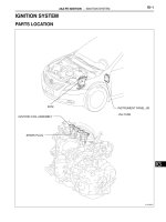
PARTS LOCATION
ECM
IGNITION COIL ASSEMBLY
SPARK PLUG
INSTRUMENT PANEL J/B
-INJ FUSE
A137459E01
IG–2
2AZ-FE IGNITION – IGNITION SYSTEM
IG
SYSTEM DIAGRAM
C11
Ignition Coil (No. 1)
ECM
+B
GND
IGT1 C24
85
IGT1
13
42
IGF
C13
Ignition Coil (No. 2)
INJ
From
Ignition
Switch
C16
Noise Filter
(Ignition RH)
+B
GND
IGT2 C24
84
IGT2
13
42
IGF
C12
Ignition Coil (No. 3)
+B
GND
IGT3 C24
93
IGT3
13
42
IGF
C14
Ignition Coil (No. 4)
+B
GND
IGT4 C24
82
IGT4
C24
81
IGF1
1
1
3
42
IGF
A137001
2AZ-FE IGNITION – IGNITION SYSTEM
IG–3
IG
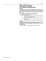
ON-VEHICLE INSPECTION
1. CHECK IGNITION COIL ASSEMBLY AND PERFORM
SPARK TEST
NOTICE:
In this section, the terms "cold" and "hot" refer to
the temperature of the coils. "Cold" means
approximately -10 to 50°C (14 to 122°F). "Hot" means
approximately 50 to 100°C (122 to 212°F).
(a) Check for DTCs.
NOTICE:
If any DTC is present, perform troubleshooting
in accordance with the procedure for that DTC.
(b) Check that sparks occur.
(1) Remove the No. 1 engine cover.
(2) Disconnect the 4 ignition coil connectors and
remove the 4 bolts and ignition coils.
(3) Using a 16 mm (0.63 in.) spark plug wrench,
remove the 4 spark plugs.
(4) Disconnect the 4 fuel injector connectors.
(5) Install the spark plug to each ignition coil, and
connect the ignition coil connectors.
(6) Ground the spark plug.
(7) Check if a spark occurs at each spark plug
while the engine is being cranked.
NOTICE:
• Be sure to ground the spark plugs when
checking.
• Replace the ignition coil if it receives an
impact.
• Do not crank the engine for more than 2
seconds.
16 mm Spark
Plug Wrench
A124849E01
A097448E01
A124396
IG–4
2AZ-FE IGNITION – IGNITION SYSTEM
IG
(c) Perform the spark test according to the flowchart
below.
(1) Check that the ignition coil connector is
securely connected.
Result
(2) Perform the spark test on each ignition coil.
1. Replace the ignition coil with a normal one.
2. Perform the spark test again.
Result
(3) Check the power supply to the ignition coil.
1. Turn the ignition switch to the ON position.
2. Measure the voltage between the terminals
of the wire harness side connector.
Standard voltage
Result
(4) Measure the resistance of the camshaft
position sensor.
Standard resistance
Result
(5) Measure the resistance of the crankshaft
position sensor.
Standard resistance
Result
Result Proceed to
NG Connect securely
OK Go to next step
Result Proceed to
OK Replace ignition coil
NG Go to next step
A124397
Tester Connection Specified Condition
1 (+B) - 4 (GND) 9 to 14 V
Result Proceed to
NG Check wire harness and connector
OK Go to next step
Temperature Specified Condition
Cold 835 to 1,400 Ω
Hot 1,060 to 1,645 Ω
Result Proceed to
NG Replace camshaft position sensor
OK Go to next step
Temperature Specified Condition
Cold 985 to 1,600 Ω
Hot 1,265 to 1,890 Ω
Result Proceed to
NG Replace crankshaft position sensor
OK Go to next step
2AZ-FE IGNITION – IGNITION SYSTEM
IG–5
IG
(6) Check the IGT signal from the ECM.
Result
(7) Using a 16 mm (0.63 in.) plug wrench, install
the spark plug.
Torque: 19 N*m (194 kgf*cm, 14 ft.*lbf)
(8) Install the 4 ignition coils with the 4 bolts and
connect the 4 ignition coil connectors.
Torque: 9.0 N*m (92 kgf*cm, 80 in.*lbf)
(9) Connect the 4 fuel injector connectors.
(10) Install the No. 1 engine cover.
2. CHECK SPARK PLUG
(a) Check the electrode.
(1) Using a megohmmeter, measure the insulation
resistance.
Standard insulation resistance:
10 MΩ or more
HINT:
• If a megohmmeter is not available, perform
the following simple inspection instead.
• If the result is 10 MΩ or less, clean the plug
and measure the resistance again.
(b) Alternative inspection method:
(1) Quickly accelerate the engine to 4,000 rpm 5
times.
(2) Remove the spark plug.
(3) Visually check the spark plug.
If the electrode is dry, the spark plug is
functioning properly. If the electrode is damp,
proceed to the next step.
(c) Check the spark plug for any damage to its threads
and insulator.
If there is damage, replace the spark plug.
Recommended spark plug
(d) Check the spark plug electrode gap.
Maximum electrode gap for used spark plug:
1.3 mm (0.051 in.)
If the gap is greater than the maximum, replace the
spark plug.
Electrode gap for new spark plug:
1.0 to 1.1 mm (0.039 to 0.043 in.)
Result Proceed to
NG Check ECM (see page ES-188)
OK Repair wiring between ignition coil
and ECM
Ground
I039522E10
A126881
Manufacturer Spark plug type
DENSO SK20R11
NGK IFR6A11
1.0 to 1.1 mm
A126880E01
IG–6
2AZ-FE IGNITION – IGNITION SYSTEM
IG
(e) Clean the spark plugs.
If the electrode has traces of wet carbon, clean the
electrode with a spark plug cleaner and then dry it.
Standard air pressure:
588 kPa (6 kgf*cm
2
, 85 psi)
Standard duration:
20 seconds or less
HINT:
Only use the spark plug cleaner when the electrode
is free of oil. If the electrode has traces of oil, use
gasoline to clean off the oil before using the spark
plug cleaner.
B062019E01
2AZ-FE IGNITION – IGNITION COIL
IG–7
IG
ENGINE2AZ-FE IGNITION
IGNITION COIL
COMPONENTS
: Specified torque
N*m (kgf*cm, ft.*lbf)
x 2
IGNITION COIL CONNECTOR
IGNITION COIL ASSEMBLY
NO. 1 ENGINE COVER
9.0 (92, 80 in.*lbf)
9.0 (92, 80 in.*lbf)
A124364E04
IG–8
2AZ-FE IGNITION – IGNITION COIL
IG
REMOVAL
1. DISCONNECT CABLE FROM NEGATIVE BATTERY
TERMINAL
2. REMOVE NO. 1 ENGINE COVER (See page EM-94)
3. REMOVE IGNITION COIL ASSEMBLY
(a) Disconnect the 4 ignition coil connectors.
(b) Remove the 4 bolts and 4 ignition coils.
INSTALLATION
1. INSTALL IGNITION COIL ASSEMBLY
(a) Install the 4 ignition coils with the 4 bolts.
Torque: 9.0 N*m (92 kgf*cm, 80 in.*lbf)
(b) Connect the 4 ignition coil connectors.
2. INSTALL NO. 1 ENGINE COVER (See page EM-121)
3. CONNECT CABLE TO NEGATIVE BATTERY
TERMINAL (See page EM-120)
A124400
A124400